Fast Sketch Recognition Using Stroke Constraint Indexing Tracy Hammond Department of Computer Science Dwight Look College of Engineering Texas A&M University, Mail stop 3112 414C Harvey R. Bright Building, College Station, TX 77840 USA +1-979-680-1789
[email protected]
Randall Davis Computer Science and Artificial Intelligence Laboratory (CSAIL) Massachusetts Institute of Technology 32 Vassar St., Room 32-237 Cambridge, MA 02139 USA +1-617-253-5879
[email protected]
ABSTRACT
General terms:
Sketching is a natural modality of human-computer interaction for a variety of tasks, including, conceptual design. Our goal is to make drawing on a computer, as close as possible to drawing on a piece of paper, by placing as few constraints on the user as possible, while still enabling computer recognition of the hand-drawn shapes. Systems should include the ability to draw shapes in any order, and to allow interspersing (i.e., starting one shape, stopping, drawing another shape, then finishing drawing the initial shape). However, allowing interspersing complicates sketch interpretation. If each shape were completed before the next was started, segmentation and interpretation need to consider only a set of chronologically contiguous strokes. In the presence of interspersing, every subset of shapes on the screen has to be examined. Many sketch systems deal with this by disallowing interspersing beyond a limited amount of time or number of strokes; those that don’t may experience exponential slowdown when many possible subshape candidates are on the screen. We believe that placing such constraints on the sketcher is unnatural. We present here an indexing technique that takes advantage of the LADDER constraint language to index each shape for efficient access later. While our recognition algorithm is still exponential, this indexing technique removes all computation except list retrieval and comparisons to improve average-time performance and to support near real-time recognition even when all possible shape subsets are used as shape candidates. This removes constraints on drawing order, providing for more natural sketch interaction. We present empirical timing data results and showing that with our technique, even with over a hundred subshape candidate lines on the page, the system recognizes new shapes in less than a second.
guages.
H5.2 [Information interfaces and presentation]: User Interfaces - Graphical user interfaces. ACM Classification:
Keywords:
Design, Human Factors, Algorithms, Lan-
Sketch recognition, pattern recognition.
INTRODUCTION
Computers have become an integral part of our lives, and thus, it is becoming increasingly important to make working with them easier and more natural. Our long-term vision is to make human-computer interaction as easy and as natural as human-human interaction. Part of this vision is to have computers understand a variety of forms of interaction that are commonly used between people, such as sketching. Computers should, for instance, be able to understand the information encoded in diagrams drawn by and for scientists and engineers. Ordinary paper offers the freedom to sketch naturally; e.g., drawing objects with any number of strokes in any order. But sketches are of limited utility to the computer unless they can be interpreted. In an attempt to combine the freedom provided in a paper sketch with the processing capabilities of an interpreted diagram, sketch recognition systems have been developed for many domains, including Java GUI creation [4], UML class diagrams [7] [14], and mechanical engineering [1]. Sketch interfaces: 1) interact more naturally than a traditional mouse-and-palette tool by allowing users to hand-sketch the diagram; 2) can connect to a back-end system (such as a CAD tool) to offer real-time design advice; 3) recognize the shape as a whole to allow for more powerful editing; 4) beautify diagrams, removing mess and clutter; and 5) notify the sketcher that the shapes have been recognized. Sketch recognition is the process of combining lower-level shapes on the screen to create higher-level shapes. These higher-level shapes are defined by the subshapes of which they are composed and constraints specifying how the subshapes fit together. To recognize all higher-level shapes, the recognition system must examine every possible combination of subshapes, as well as every permutation of these subshapes. This implies that any straightforward algorithm would take exponential time, which is clearly impractical for any non-trivial sketch. To combat this problem, recognition systems have placed
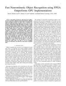
drawing requirements on the user [18] [15], such as requiring users to draw each shape in its entirety before starting the next shape, or forcing users to draw each shape in a single stroke. This produces an unnatural drawing style, as there are many domains where it is natural to intersperse the drawing of objects. Mahoney et. al. [16] have discussed the inherent complexity involved in the structural matching search task. They reduce the problem to a constraint satisfaction subgraph problem, but their solutions still contain empirically exponential results. Our goal is to make sketch systems as natural as possible by placing as few requirements on the user as possible. In our experience observing users sketch in a variety of domains, we have found it not uncommon for someone to draw part of a shape, stop, continue drawing other objects in diagram, and then come back to finish the original shape. For instance, Figure 1 shows an example in mechanical engineering. We have seen interspersing in software design, where UML class diagram designers sometimes initially draw connections as simple dependency associations, until most of the classes have been drawn, at which point they will have a better understanding of the emerging design, and make a better decision about the type of association that would be appropriate between two objects. This will cause them to add different kinds of arrowheads to the associations drawn earlier, producing an interspersed sketch [7]. We have also witnessed interspersing in electrical engineering; sketchers add voltage directions only after most of the circuit has been drawn. If we are to allow interspersed drawing, our system must be able to recognize shapes by how they look rather than how they were drawn. In order to recognize completed shapes while still allowing incomplete, interspersed shapes, the recognition system must examine all possible subsets of shapes, i.e., the power set of all the shapes on the screen, which is of course exponential in |S|, where S is the set of shapes drawn, and S is the size of that set. Yet we also want to keep interaction close to real-time. This paper presents an indexing technique for sketch recognition that examines all 2|S| shape subsets when attempting to recognize new shapes, but uses efficient indexing to keep recognition performance close to real-time. The technique takes advantage of the LADDER constraint language to index each stroke efficiently for quick access later. This paper also reports timing data that supports the claim that the recognition of new shapes can be kept close to real-time even when all possible shape subsets are considered.
OrientationDependent Constraints: OrientationIndependent constraints:
Composite Constraints (subset):
Other Constraints:
HORIZONTAL , VERTICAL , NEG SLOPE , POS S LOPE , ABOVE , LEFT O F, HORIZ A LIGN , VERTA LIGN , POINTS D OWN , POINTS L EFT, POINTS R IGHT, and POINTS U P ACUTE , ACUTE D IR , ACUTE M EET, BISECTS , COINCIDENT, COLLINEAR , CONCENTRIC , CONNECTS , CON TAINS , DRAW O RDER , EQUAL A NGLE , EQUAL A REA , EQUAL L ENGTH , IN TERSECTS , LARGER , LONGER , MEETS , NEAR , OBTUSE , OBTUSE D IR , OBTUSE M EET, ON O NE S IDE , OPPO SITE S IDE , PARALLEL , PERPENDICU LAR , and SAME S IDE . SMALLER , BELOW, RIGHT O F, ABOVE L EFT, ABOVE R IGHT, BELOW L EFT, BELOW R IGHT, CENTEREDA BOVE , CENTERED B ELOW, CENTERED L EFT, CENTERED R IGHT, CENTERED I N , LESS T HAN , and LESS T HAN E QUAL EQUAL , GREATERT HAN , GREATERT HAN E QUAL , OR and NOT.
Table 1: LADDER Constraints
that when we define a new shape, it is seamlessly added to the repertoire of the recognition system without stopping the system or recompiling. LADDER Constraints Our indexing technique works by indexing the geometrical properties of a shape for use in recognition. LADDER provides a vocabulary of geometric constraints (listed in Table with which to describe shapes, such as PERPENDIC ULAR . Constraints may be either orientation-dependent or orientation-independent. The vocabulary also includes EQUAL , GREATERT HAN , and GREATERT HAN E QUAL , allowing comparison of any two numeric properties of a shape (e.g., stating that the height is greater than the width). The vocabulary also contains a number of constraints that can be composed from other constraints. We include these to simplify descriptions and to make them more readable. The constraint modifiers OR and NOT are also present to allow description of more complicated constraints.
RECOGNITION
Our approach to recognizing shapes by how they look rather than how they were drawn is based on using geometric descriptions of each shape. We describe shapes using the LADDER (a LAnguage for describing Drawing, Display, and Editing for use in Recognition)[8] shape definition language, and have developed software to automatically generate shape recognizers from these descriptions (see [9]). The techniques described here differ from those in [9] in that 1) we modified the recognition algorithm to use techniques presented in this paper to make it faster, and 2) translation from a shape description to its recognizer is done internally, which means
Figure 2: An arrow with an open head.
A domain description lists the shapes to be recognized in the domain, along with a description for each shape that indicates how it is to be recognized, display, and edited. Figure 3, a partial1 shape description, showing the components (three 1 LADDER shape descriptions can describe both the geometric properties of the shape, and how the shape should be displayed and edited once it has been recognized. Since editing and display of a shape is not important for the purposes of this paper, we omit them from our discussion.
Figure 1: Five snapshots in the design of a car on a hill in mechanical engineering. Not that the top of the ground is drawn first, followed by the car base, to ensure that they are parallel. Then wheels (which act as the connection between the car and the ground) were added. The wheels were attached to the car only after the car was completed. The first started object, the ground was completed last, since its purpose in completion was more in terms of general functioning when attaching it to a CAD system than in design.
define shape OpenArrow description "An arrow with an open head" components Line head1 Line shaft Line head2 constraints coincident shaft.p1 head1.p1 coincident shaft.p1 head2.p1 coincident head1.p1 head2.p1 equalLength head1 head2 acuteMeet head1 shaft acuteMeet shaft head2 aliases Point head shaft.p1 Point tail shaft.p2
define shape TriangleArrow description "An arrow with a triangle-shaped head" components OpenArrow oa Line head3 constraints coincident head3.p1 head1.p2 coincident head3.p2 head2.p2 aliases Line shaft oa.shaft Line head1 oa.head1 Line head2 oa.head2 Point head oa.head Point tail oa.tail Figure 5: The description for an arrow with a triangleshaped head, as shown in Figure 4.
Figure 3: The partial description for an arrow with an open head, as shown in Figure 2.
included in the shape descriptions.
Figure 4: An arrow with a triangle head.
lines) and the constraints that make up an O PENA RROW. New shapes are defined hierarchically in terms of previouslydefined shapes and the constraints between them. For example, Figure 5 shows a shape description for a T RIANGLE A R ROW created from an O PENA RROW and a line2 . Geometric constraints define the relationships between those components. For example, the O PENA RROW shape definition requires that the HEAD 1 and SHAFT meet at a single point and form an acute angle from line HEAD 1 to line SHAFT when traveling in a counter-clockwise direction. Signal Noise versus Conceptual Variations
The LADDER shape description is translated into a recognizer for that shape using techniques from [9]. The recognition handles signal noise, but conceptual variations must be 2 An
aliases section in a shape definition is available to simplify hierarchically-defined descriptions, allowing components to be renamed for ease of use later. For example, the O PENA RROW definition has aliases for the HEAD and TAIL to simplify the T RIANGLE A RROW description.
By signal noise we mean the unintentional deviations introduced into a shape by the imprecision of hand control. For instance, when drawing a square, all four sides may turn out to be of different lengths even though the sketcher meant for them to be the same length. By conceptual variations, we mean the allowable variations in a symbol that are drawn intentionally. For example, a capacitor in an electronic circuit may be drawn as two parallel lines, or as one straight and one curved line (see Figure 6).
Figure 6: A capacitor can be drawn with two lines or a line and a curve.
In our system, signal noise is handled by the recognition system. For example, the system can successfully recognize a quadrilateral with uneven sides as a square because the EQUAL L ENGTH constraint has some built-in tolerance (discussed below). Thus, shapes should be described to the
Figure 7: Stages of square recognition; a) original strokes, b) primitive shapes, c) joined/cleaned primitives, and d) higher-level recognition.
system without accounting for signal noise, i.e., as if drawn perfectly (e.g., a square should be described as having equal length sides). As the system does not automatically take into account the possible conceptual variations (indeed, how could it?), they must be provided for in the shape descriptions. Other signal errors include a sketcher intending to draw a single line, but using several strokes to do so. In order for the system to deal with these phenomena, it first joins lines by merging overlapping and connecting lines. Figure 7 shows the steps that go into recognizing a square. Figure 7a shows the original strokes. Figure 7b shows the original strokes broken down into primitives. The system has recognized the strokes as lines or polylines; the figure shows the straightened lines that were recognized by the recognition system. (The dots represent their endpoints.) Figure 7c shows the primitives (line segments, in this example) joined together to form larger primitives (again lines, in this example) using the merging techniques described above. Figure 7d shows the higher-level recognition performed on the recognized shapes; the method for this is described int the next section. A higherlevel shape can then use the square as one of its components. Constraint Tolerances
In our approach, signal error is handled by the shape recognizer by giving each constraint its own error tolerance, chosen to be as close as possible to perceptual tolerance, i.e., the tolerance that humans use. Human perceptual tolerance is context-dependent, depending on both the shape in question and other shapes on the screen. Table shows constraints and the error tolerances we use. Note that some constraints have an absolute tolerance, while others are relative. Some
constraints have a negative tolerance, which means the constraint has to be not only geometrically satisfied, but also perceptually satisfied, meaning that humans have to be able to perceive that the constraint is true. To give an example, a shape that is left of another shape by one pixel is geometrically left of another shape, but is not perceptually left of another shape, as it difficult for a human to perceive such a small distance. To ensure that a constraint is perceptually satisfied, we add a buffer zone to the tolerance. Perceptual error tolerances were determined empirically and based from grouping rules and singularities from gestalt principles [6]. Grouping rules attempt to mimic how people perceptually group objects, using concepts such as connectedness, nearness, and other principles. Singularities describe which geometrical shape properties are most noticeable. For instance, humans are particularly sensitive to horizontal and vertical lines and can quickly label a line as horizontal or not horizontal, and identify if a line deviates from horizontal or vertical by as little as five degrees. Humans have considerably more difficulty identifying lines at other orientations, such as 35 degrees, and would have a much more difficult time determining if a particular line was 30, 35, or 40 degrees. Humans tend to group together the angles between 15 and 75 degrees as positively-sloped lines [6]. 3 When drawing an ideal positively-sloped line, users tend to draw an angle close to 45 degrees and when drawing a ideal horizontal line they tend to draw an angle close to 0 degrees. However, since differences are much more perceptually important close to horizontal, we have mad the tolerance less for near singularities (such as HORIZONTAL, VERTICAL, PARALLEL, and PERPENDIC ULAR ). Based on the mean error of only 2.8 degrees for angle singularities shown in the footnote, you may expect the singularity tolerances to be even smaller. However, because the perceptual error tolerances are used to remove possible shapes from our recognition results, we choose error tolerances that are slightly smaller (while we would require such a small tolerance when trying to generate a perceptually true constraint, such as in [10]). INDEXING ALGORITHM
Our first implementation of the system generated all possible subsets of the shapes on the screen and tested each shape to determine whether all of the necessary constraints held. While we attempted to speed this up by taking advantage of a limited amount of caching using the Rete[5] algorithm, the exponential inherent in testing all subsets overwhelmed the system, which slowed unacceptably after about 30 individual strokes. 3 To calibrate how sensitive people are, we showed nine people a total of 116 lines in a random orientation between 0 and 180 degrees. Users were asked to report the orientation of the line as accurately as possible. We grouped the lines into two groups 1) angles with orientations within 10 degrees of horizontal or vertical (0-10, 80-100, and 170-180 degrees) and 2) angles with orientations not within 10 degrees of horizontal or vertical (10-80, 100-170). When labeling lines from group 1 (near horizontal or vertical), users had a mean error (absolute value of the reported angle minus the actual angle) of 2.8 degrees and a variance of 4.95. When labeling lines from group 2 (far from horizontal or vertical), the users had a mean error of 7.64 and a variance of 25.77. As shown by the variance, large errors between the actual orientation and the correct orientation were common: 24 lines had an error greater than 10; 8 lines had an error greater than 15; and 2 lines had an error greater than 20. The two groups were significantly different with a p value of less than .001.
Current Implementation
Our current implementation is done in three stages: 1) domainindependent primitive finding, 2) domain-independent constraint indexing, and 3) domain-dependent shape formation. When a stroke is drawn (and has not been identified as an editing gesture), low-level recognition is performed on it. During processing, each stroke is broken down into a collection of primitive shapes, including line, arc, circle, ellipse, curve, point, and spiral, using techniques from Sezgin [19]. Corners used for segmentation are found using a combination of speed and curvature data (as in Sezgin [19]). By breaking strokes down into these primitives, and performing recognition with primitives, we can recognize shapes drawn using multiple strokes, and handle situations in which a single stroke was used to draw multiple shapes. Domain-Independent Primitive Finding
horizontal vertical posSlope negSlope coincident coincident bisects bisects near near concentric concentric sameX sameX sameY sameY equalSize parallel perpendicular acute obtuse contains above leftOf larger
angle angle angle angle x location y location x location y location x location y location x location y location x location width y location height size angle angle + 90 angle + 40 angle + 130 min X,Y & max X,Y y location x location size
10 degrees 10 degrees 35 degrees 35 degrees 10 pixels 10 pixels (length / 4) pixels (length / 4) pixels 50 pixels 50 pixels (width / 5) + 10 pixels width / 5 + 10 20 pixels 20 pixels 20 pixels 20 pixels (size / 4) + 20 pixels 15 degrees 15 degrees 30 degrees 30 degrees -5 pixels -5 pixels -5 pixels -5 pixels
Table 2: Constraints and their error tolerances. (Note: size = length of diagonal of bounding box. We use this formula instead of the area to enable us to compare lines to two-dimensional shapes. Rubine uses the same formula for size when calculating feature number five. [18])
If a stroke has multiple primitive interpretations, all interpretations are added to a pool of interpretations, but a single interpretation is chosen for display. For example, both the L INE and A RC interpretation of the S TROKE in Figure 8A will be added to the pool for recognition using any of the interpretations. We want to ensure that the shape recognition system chooses only one interpretation of a single stroke. In order to ensure that only one interpretation is chosen, each shape has an ID, and the appropriate bookkeeping is done to ensure that while multiple interpretations are kept while the system is working (i.e., recognizing), the final displayed result contains only a single interpretation for each stroke. In cases when a stroke is determined to be composed of several primitives, (e.g., the P OLYLINE interpretation in Figure 8B), the S TROKE is segmented, the segmented substrokes added as components of the original full S TROKE. Further interpretations can use either the full stroke, as the C URVE does in Figure 8B, or one or more of the segmented substrokes. This allows several shapes to be drawn with a single stroke. Domain-Independent Constraint Indexing
We would prefer to place as few drawing requirements as possible on the sketcher, and must as a consequence find a way to deal with the exponential. While our solution does not eliminate the exponential, we can use indexing to do a significant amount of the computation ahead of time. Because the indexing of a shape is dependent only on its own properties, the time it takes to index a specific shape is not exponential; (it is actually logarithmic in the number of shapes on the screen because several of the properties are inserted into a sorted hash map). The indexing process occurs only once for each shape, when it shape is drawn or recognized. The recognition process is still exponential (as it must be if we are still to consider all possible subshapes), but in practice, it is very fast because most of the process has been moved to the indexing pre-processing stage, which is not exponential. When a new shape is recognized, the system computes its properties, including its orientation, angle, location, and size. Each property has its own data structure, permitting quick
Figure 8: Multiple interpretations and their identifiers are added to the recognition pool. In A, Stroke 0 has two interpretations; Line 1 and Arc 2 are each composed from Stroke 0. In B, Stroke 0 can be broken down into three Strokes (1,2,3). Stroke 0 has two interpretations, Curve 4 composed of Stroke 0 (and thus also Strokes 1,2,3) and three lines: Line 5 composed of Stroke 1, Line 6 composed of Stroke 2, and Line 7 composed of Stroke 3.
retrieval of shapes with the desired property value. For instance, the angle data structure is used when searching for horizontal lines or lines of equal angle. When a line is recognized, its angle is measured and categorized as “horizontal,” “posSlope,” “vertical,” or “negSlope.” The category is used as the key for a hash map whose values are a linked list of shapes. This allows constant-time retrieval of a list of all of the lines in a particular orientation. We also want to find parallel lines, so exact angles are used to add the shape to a sorted map list. This allows for a logarithmic-time retrieval of the list of lines that are close to a particular angle. Since it is faster to retrieve shapes with angles close to our predefined categories, we choose to do so when it is feasible. Once properties are computed and indexing has been done, the system tries to see whether a higher-level shape can be made from this new shape and shapes already on the screen. We need to check whether this new shape can be a part of any of the shapes defined in the domain description. For each shape in the domain, the system assigns the new shape to each possible slot component. If there are n domain shapes, and each shape S is composed of m components (C1 to Cm ), then the just processed shape is assigned to each slot separately in different shape templates. Figure 9 shows an example. A newly interpreted line is added to the system. The system checks to see if the newly interpreted line can be used to create any of the shapes in the domain. (In this example, we are checking only the domain shape O PENA RROW.) The system creates three templates, one for each component of the O PENA RROW of the correct type (in this case a line), assigning the just processed line to a different component to see if an O PENA RROW can be formed with that component. 4
The system then computes the function Lij = f (Si , Cj ), which returns a list Lij of shapes of type Si and the components that make up these shapes, which can be formed with the just processed shape assigned to component Cj . For example, if the domain description includes 10 shape descriptions, and O PENA RROW is the third description, Si = O PE NA RROW (shown in Figure 3. An arrow has three slots (one for each line). If the system puts the recently drawn shape 4 We state that three templates for explanation simplicity, but in actuality, when a single line is drawn, the system creates six arrow templates. The recognition creates two copies of every line, one in each direction. (i.e., the second is equal to the first with the endpoints flipped.) Each directional line is assigned one at a time to each component of three arrow templates. This is actually not a phenomenon applied specifically to lines, but any group of multiple interpretations using a single subshape.
Figure 10: Multiple O PENA RROW interpretations are possible using the center stroke as the SHAFT.
into slot 2, then Cj = SHAFT. Thus, Lij returns a list of all of the possible O PENA RROW’s with the most recently drawn shape acting as the SHAFT of the stroke. The length of Lij may be 0 (no such interpretations are possible), 1 (one interpretation is possible), or > 1 (multiple interpretations are possible, see Figure 10). The new shape can be placed in any slot in any template. P is the union of all the possible shapes formed with the new shape. P=
Sn
i=1
Sm
j=1 (Lij
= f (Si , Cj ))
Each template currently has only one slot filled (with the new shape). To compute Lij = f (Si , Cj ), the system assigns all of the other shapes on the screen to the other slots on the template, so that each slot on the template holds the possibilities for that slot. The next stage is to reduce the possibilities for each slot. This is done from the indexing data structures that were created previously. The system holds a list of unchecked constraints. In order to remove a shape from the list of possible shapes in a slot, we have to be sure a shape cannot be formed using that shape. If only one of the component slots referenced by the constraint contains more than one possible shape, then we can determine for certain which shapes satisfy that constraint, and are allowed in the final shape composition. Let Ti be the list of constraints from Si that are not yet solved. Let Ot be the number of slots for constraint t with more than
Figure 9: For each shape added to the system, the recognition system checks if the new shape can be a piece of any of the higher-level shapes recognizable by the domain. This figure shows takes a new line added to the recognition system. The system checks if that line combined with any of the shapes on the screen can form an arrow (one of the higher-level shapes in the domain). The system checks if the new line can be any of the three lines that compose an arrow and makes a template for each of these possibilities.
one component in the possibilities list. For each constraint with only one slot (or no slots) with more than one component (Ot 1. In this case, the system branches the template, choosing the slot with more than one remaining possible assignments that has the fewest such possible assignments. It makes a new copy of the template for each of the possible assignments for that slot, placing only one in each template, then continues trying to solve the remaining unsatisfied constraints on each of the templates. This branching process can of course cause its own exponential slowdown. The system’s near real-time performance results from the fact that 1) branching does not happen often because most of the shapes on the screen do not obey the required constraints, and thus, many shapes are removed from the possibility list at once. (For example, for example, the COINCIDENT constraint. It is uncommon for many shapes to be drawn at the same location, so many possibilities are removed simultaneously from the possibilities list.) And, 2) even in the worst case where every query results in a branching factor, the process of checking the constraints is a small proportion of the overall running time (see the Results section below) This is because the exponential part of the algorithm performs only list retrievals (which has been made fast with the use of sorted hash maps and other data structures) and list intersections. At the end of this stage, we have a list P of all the shape interpretations and their components. All interpretations are added to the recognition system, but a single interpretation is chosen for display. The system chooses to display the interpretation that is composed of the largest number of primitive shapes (i.e., the solution that accounts for more data). Creating shapes with the largest number of primitive shapes also results in fewer more-complicated shapes filling the screen.
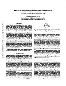
Figure 12: The left shows the originally drawn strokes. The middle interpretation is made up of a line and a square. The right interpretation is made up of an arrow and two lines.
Figure 13: Recognition Stress Test
For example, in Figure 12, we choose the square interpretations rather than the arrow for display purposes, as the square accounts for four primitive, simplifying the diagram to only two higher level shapes, whereas the arrow interpretation accounts for only three lines, simplifying the diagram to three higher level shapes. Figure 11: Line L7 has been added to the screen where previous shapes L1, L2, L3, L4, L5, and L6 already exist. The top right shows the initial template when assigning the new line (with a particular orientation) to the HEAD 2 slot of the arrow. Note that all other shapes on the screen are added. The system then attempts to satisfy each of constraints, removing remove shapes that do not satisfy a constraint from the template. 1) The system tries to satisfy the constraint EQUAL L ENGTH and removes all shapes in the HEAD 1 slot of the template that are not of equal length to L7. The EQUAL L ENGTH constraint is now completed and removed from the list of constraints yet to be satisfies. 2) The system attempts to satisfy the LONGER constraint, but since both arguments have more than one shape in the slot, the constraint is postponed. 3) The system tries to satisfy the COIN CIDENT constraint and removes L2, L3, and L5 from the HEAD 1 slot. Because L4 is now the only possibility for the HEAD 1 slot, it is removed from the SHAFT slot, since the same shape cannot be used for both slots. 4) The system tries to satisfy the second COIN CIDENT constraint is processed, but since none of the shapes in the SHAFT slot can be coincident with L4, the SHAFT slot is empty, and the system determines that an O PENA RROW cannot be formed with the new shape filling in the HEAD 1 slot.
If the recognition process finds multiple interpretations (i.e., |P| > 1), the system adds both interpretations to the recognition system for use in finding higher-level shapes. The system uses the bookkeeping system described earlier to ensure that only one final interpretation is chosen for display for each shape. with a common subshape, the system adds all interpretations to the recognition system for use in finding higher-level shapes. The system uses the bookkeeping system described earlier to ensure that only one final interpretation is ultimately chosen for display. RESULTS
In a test on a tablet PC with 1GB of RAM and a 1.73 GHz processor, the system recognized a resistor containing six lines in less than a second, with 189 other shapes (besides the six lines creating the resistor) on the screen (see Figure 13), 3 of which were higher-level shapes such as resistors, and the other 186 were random lines on the screen. We added many random lines on the screen to provide many possible recognition choices as a sort of stress test. If the user draws many strokes quickly, the system can slow down because there is a constant amount of time necessary to preprocess each stroke. We analyzed the running time of the recognition system using JProbe [17], and determined that with many unrecognized shapes on the screen, approximately 74% of the recognition time was spent breaking down the strokes into lines. The next greatest amount of time was spent indexing the lines drawn; each shape took a constant
amount of time in the number of shapes on the screen to compute the property values and a logarithmic amount time to insert in to the appropriate data structure. A very small portion of time was used to do the actual recognition even though the last portion is exponential in the number of strokes on the screen. Because of our indexing, the recognition portion takes a small amount of time, with little to no constraint calculation, as the system was only doing list comparisons. As a result, the system still reacts in what can be considered close to real-time, even with 186 shapes on the screen.
PREVIOUS WORK
DISCUSSION LADDER Limitations
Indexing data to provide speed-up is of course not a new idea. It has been used, for example, in the closely related field of vision object recognition [21] [20] [2] [13]. Indexing sketches to search for photos has been done by [3] [12]. The authors have previously used recognized sketches to index software design meetings [11]. This work appears to be the first use of the idea in support of unconstrained sketch recognition. By breaking the strokes down to line, curve, and ellipse segments, we were able to define shapes in geometric terms, then perform indexing on these terms, a luxury not afforded when indexing photo images or non-geometric sketches (such as an artist’s sketch).
LADDER can be used to describe a wide variety of shapes, but is limited to the following class of shapes.
FUTURE WORK
• LADDER can only describe shapes with a fixed graphical grammar. The shapes must be drawn using the same graphical components each time. For instance, we cannot describe abstract shapes, such as people or cats, that would be drawn in an artistic drawing. • The shapes must be composed solely of the primitive constraints contained in LADDER and must be differentiable from the other shapes in the language using only the constraints available in LADDER. • Pragmatically, LADDER can only describe domains that have few curves or where the curve details are not important for distinguishing between different shapes. Curves are inherently difficult to describe in detail because of the difficulty in specifying a curve’s control points. Future work includes investigating more intuitive ways of describing curves. • Likewise, LADDER can only describe shapes that have a lot of regularity and not too much detail. If a shape is highly irregular and complicated, so that it cannot be broken down into subshapes that can be described, it will be cumbersome to define. Recognition Limitations
• We are limited to recognize only those shapes that are describable in LADDER. • It is possible to contrive an example that will cause our approach to branch very often, causing significant slowdown. This will arise if someone draws similar shapes repeatedly on top of themselves. The system would have a very large number of branches, because it would be difficult to eliminate a large number of possibilities in a slot for a single constraint. • Shapes that are highly symmetric will cause many interpretations that look identical but that have different line assignments. For example, consider a square. The square can be rotated and each of the lines flipped, and thus depending on the form of the description, sixteen interpretations may exist. All of these interpretations must be kept because higher-level shapes formed from that square may require the labeling that occurs in any one of the recognitions. Thus, the number of shapes in the recognition pool can grow exponentially as shapes are recognized. Luckily, in practice, most interpretations are ruled out based on the shape description.
The indexing algorithm described in this paper was limited to the geometric constraints and LADDER limitations described above. We would like to remove some of these limitations by combining the techniques presented in this paper with those that have proved useful in work in vision. By processing and indexing vision features used for recognition, and concurrently indexing on geometric properties as described in this paper, we can quickly access shapes that have the needed visual and geometric features. As a very simple example, vision recognition techniques can easily locate areas of high density ink, or shading, which we are currently not able to recognize using our geometric recognition techniques. We would like to combine vision and sketch-based features to perform more robust recognition and perhaps recognize a larger class of objects. CONCLUSION
This paper describes an indexing algorithm for use in sketch recognition. Shapes are indexed as they are being drawn or and when they are recognized, using a vocabulary of geometric properties that permits fast lookup subsequently. Geometric constraint indexing allows us to search through all possible subsets of the shapes on the screen quickly, facilitating recognition of higher-level shapes. Because we can quickly search through all possible subset shapes, we no longer have to limit the search space and can allow sketchers to intersperse the drawing of incomplete shapes with little speed penalty. By enabling a less constrained drawing style, we provide a more natural sketch recognition user interface. Our results show that the system continues to run in near realtime, even when over a hundred lines are on the page. ACKNOWLEDGMENTS
This work was supported in part by the MIT Oxygen Project, by the MIT/Microsoft iCampus Project, by Intel, Inc., and by Pfizer, Inc. REFERENCES
1. Christine Alvarado. A natural sketching environment: Bringing the computer into early stages of mechanical design. Master’s thesis, MIT, 2000. 2. Sameer Antani, Rangachar Kasturi, and Ramesh Jain. A survey on the use of pattern recognition methods for abstraction, indexing, and retrieval of images and video. Pattern Recognition, 35:945–965, 2002.
3. Alberto Del Bimbo and Pietro Pala. Visual image retrieval by elastic matching of user sketches. IEEE Transactions on Pattern Analysis and Machine Intelligence, 19(2):121–132, 1997. 4. Anabela Caetano, Neri Goulart, Manuel Fonseca, and Joaquim Jorge. JavaSketchIt: Issues in sketching the look of user interfaces. Sketch Understanding, Papers from the 2002 AAAI Spring Symposium, 2002. 5. Ernest Friedman-Hill. Jess, the java expert system shell. http://herzberg.ca.sandia.gov/jess, 2001. 6. E. Goldmeier. Similarity in visually perceived forms. In Psychological Issues, volume 8:1, 1972. 7. Tracy Hammond and Randall Davis. Tahuti: A geometrical sketch recognition system for UML class diagrams. AAAI Spring Symposium on Sketch Understanding, pages 59–68, March 25-27 2002. 8. Tracy Hammond and Randall Davis. LADDER: A language to describe drawing, display, and editing in sketch recognition. Proceedings of the 2003 Internaltional Joint Conference on Artificial Intelligence (IJCAI), 2003. 9. Tracy Hammond and Randall Davis. Automatically transforming symbolic shape descriptions for use in sketch recognition. Proceedings of the Nineteenth National Conference on Artificial Intelligence (AAAI-04), pages 450–456, 2004. 10. Tracy Hammond and Randall Davis. Interactive learning of structural shape descriptions from automatically generated near-miss examples. Intelligent User Interfaces (IUI), 2006. 11. Tracy Hammond, Krzysztof Gajos, Randall Davis, and Howard Shrobe. An agent-based system for capturing and indexing software design meetings. In Proceedings of International Workshop on Agents In Design, WAID’02, 2002. 12. T. Kato, T. Kurita, N. Otsu, and K. Hirata. A sketch retrieval method for full color image databases - query by visual example. 11th IAPA International Conference on Pattern Recognition, pages 530–533, 1992. 13. M. Lades, J.C. Vorbruggen, J. Buhmann, J. Lange, C. von der Malsburg, R.P. Wurtz, and W. Konen. Distortion invariant object recognition in the dynamic linkarchitecture. IEEE Transactions on Computers, 42(3):300–311, March 1993. 14. Edward Lank, Jeb S. Thorley, and Sean Jy-Shyang Chen. An interactive system for recognizing hand drawn UML diagrams. In Proceedings for CASCON 2000, page 7, 2000. 15. Allan Christian Long. Quill: a Gesture Design Tool for Pen-based User Interfaces. Eecs department, computer science division, U.C. Berkeley, Berkeley, California, December 2001.
16. James V. Mahoney and Markus P. J. Fromherz. Three main concerns in sketch recognition and an approach to addressing them. In Sketch Understanding, Papers from the 2002 AAAI Spring Symposium, pages 105– 112, Stanford, California, March 25-27 2002. AAAI Press. 17. Inc. Quest Software. Jprobe. website, 2006. 18. Dean Rubine. Specifying gestures by example. In Computer Graphics, volume 25(4), pages 329–337, 1991. 19. Tevfik Metin Sezgin, Thomas Stahovich, and Randall Davis. Sketch based interfaces: Early processing for sketch understanding. In The Proceedings of 2001 Perceptive User Interfaces Workshop (PUI’01), Orlando, FL, November 2001. 20. F. Stein and G. Medioni. Structural indexing: Efficient 3-d object recognition. IEEE Transaction on Pattern Analysis And Machine Intelligence, pages 125– 125, 1992. 21. Mark R. Stevens, Charles W. Anderson, and J. Ross Beveridge. Efficient indexing for object recognition using large networks. in proceedings of IEEE International Conference on Neural Networks, 1997.