KAMITSUNA, H., SHIBATA. T., KURISHIMA. K., and IDA, M.: '10- and 39-GHr-hand InP/lnCaAs direct optical injection-locked oscillator ICs for optoelectronic clock recovery circuits', IEEE MTT-S Inl. Microw Synp. Dig., 2002, THZF4 5 OREILLY, J.J., LANE, P.M., HEIDEMANN, R., and HOFSTETTER. R.: '@tical generation of very narrow linewidth m i l l h e m wave signals', Elecrmn. Len, 1992, 28, (25), pp. 2309-2311 6 IDA, M.,KURISHIMA, K., NAKUIMA, H., WATANABE, N., and YAMAHATA, S.: 'Undoped-emitter InP/lnGaAs HBTs for high-speed and low-power applications'. IED Int. Electron Device Mtg Tech. Dig., San Francisco, CA, USA, 2000, pp. 854-856
4
.....
,
i-
.....
Fast transient response DCf DC converter for low output voltage A. Barrado, R. Vizquez, A. Lizarn, J. Pleite and E. Olias A new iltemative lo achieve f a a mnsient response DC/DC switching converters to feed devices such a$ microprocessorsand digital signal pmcesson is presented. The topology of the switching source is composed of two buck conveners connected in parallel, each one having different aims, controlled by means of the linear-nonlinear CO"tm1.
Introduction: Experiments with microprocessors and digital signal processors (DSPs) have led to very important developments in recent years. As a consequence, nowadays these devices require power supplies with low output voltage a n 4 this being the main challenge, high current slew rate [I]. Different techniques have been used to improve the transient response: increasing the bulk capacitor in the output filter; a bigger bandwidth; and changing the topologies. Concerning the technique of changing the topologies, some interesting solutions have been presented in recent years, such as the voltage regulator module with interleaving techniques [I, 21 and hybrid sources [3-51. In this Letter we present a new DC/DC switching converter, the fast response double buck (FRDB) converter, composed of two buck converters connected in parallel, each one having different features and aims, and controlled by means of the linear-nonlinear control. The aim is to reduce the recovery time (tn) of the output voltage under a load current step, limiting, at the same time, the vaiation of the output voltage (AVO-). The topology, the control, the operation principle and the experimental results are presented.
Proposed topology: Fig. I shows the block diagram of the FRDB converter. The topology of this converter is composed of two switching sources (in this case with buck topology, Fig. 2) connected in parallel. Both sources have to be designed with different purposes. The main switching source must he designed to work in steady-state operation, and therefore with a good stability and a low output voltage ripple, hut as a consequence with slow response. The auxiliary switching source must be designed to work in transient operation. The main aim of this source is to provide the required high current slew rate. Therefore, topologically, the principle is to keep the main switching source operating all the time, connecting the auxiliary switching source only at the edges of the load current steps to complement the main source performance in order to fulfil the requirements.
Fig. 2 Simplrfied dingram qfFRDB eonverler
Control strategy To regulate the FRDB converter the combined linear-nonlinear control (LnL control) [SI is used. The LnL control is based on the utilisation of a threshold hand (2AVo) (Fig. 3). This hand presents two limits, a higher threshold (HT, Vo +AVO) and a lower threshold (LT, Vo - AVO). If the output voltage is within the threshold hand only the main switching source operates, in this case like a typical buck converter with linear control. If the output voltage goes out of the threshold hand the auxiliary switching source and the nonlinear control are connected (E/D and L/NL inputs are set to 1, Fig. 2). '0
a
I
I
(L,
b
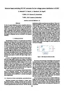
Fig. 3 FRDB ron~erfer waveforms
Load cucrenl steps b Oulmt voltsee Y
c DUG cycle " d L/NL and E/D selection inputs e Injected current by auxiliary source
The threshold logic and the duty cycle saturation and reset logic in nonlinear control (Fig. 2) are used to detect whether the output voltage is within the threshold band as well as whether the output voltage is above the higher threshold or below the lower thrcshold. The linear-nonlinear selection input (L/NL) of the multiplexer (MUX) selects either the output of the linear control, with low level, when the output voltage is within the threshold band or the output of the nonlinear control, with high level, when the output voltage is out of the threshold band. The input E/D of the driver in auxiliary source is used to enable (set to I) or to disable (set to 0) the driver,
ELECTRONlCS L E T E R S
12th September 2002 Vol. 38 No. 19
1127
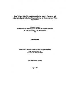
The operation principle is shown in Fig. 3. In steady-state operation, the output voltage is within the threshold band, the grey area in Fig. 3b; the main buck converter works with linear control and almost constant duty cycle, Fig. 3c; the L/NL input is at low level to select linear control, Fig. 3 d and the auxiliaty source does not inject any current, Fig. 3e, since E/D input is set to 0 like LJNL input. When a load current step occurs, if the output voltage exceeds the limits, the input L/NL and E/D are set to 1 and the buck converters, main and auxiliary, start to work with nonlinear control, Fig. 3d. The duty cycle saturation and reset logic block forces to 1 the duty cycle if lower threshold is surpassed, or it sets the duty cycle to 0 if the output voltage is above the higher threshold Fig. 3c. The auxiliary source simultaneously injects current to the output if the output voltage is below the lower threshold or it takes the current out from the output if the output voltage is above the higher threshold, Fig. 3e. Therefore, the auxiliay source forces the output voltage to be within the thresholds, Fig. 36. It is important to emphasise that the nonlinear control and the linear conml are independent. Therefore, instabilities are not produced when the output voltage retums into the threshold band and the linear control has to regulate the converter again. Experimental results: To check the features of the proposed power supply, a converter has been built according to the fallowing specifications: output voltage, I .5 VDC; input voltage, 5 VDC; maximum load current step, 16A. As a brief summary of experimental results, Fig. 4 shows the transient response of a typical buck converter with linear control and the FRDB converter.
A. Barrado, K. Vazquez, A. Lazaro, 1. Pleite and E. Olias (Power Electronics Systems Group of the Universidad Carlos I l l de Madrid. Avda. de la Uniuersidod, 30. 2x911 Leganb, Madrid, Spain) E-mail:
[email protected] References 1 ZHOU. x.. WONG. F-L.. xu. P.. LEE. F.c..and HUANG. AO.: 'Investisation of candidate VRM topologies for' ful& micmproce&, 1EEF Tmm Power Electron., 2000, 15, (6). pp. 1172-1 182 2 WEI, J., XU.P., W.H:P, LEE.F.C., YAO, K., and YE.M.: 'Comparison ofthree
topology candidates for 12V VRM'. APEC'OI, Anaheim, CA, USA, 2001.. DD. .. 245-251 3 Vi\zouEZ. R., BARRAW, A,, OLiAS, E., and L&ARO. h.: 'Theoretical study and implementation of a high dynamic perfomanc,:, high efficiency and low voltage hybrid power supply'. PESC'OI, Vanaouver, Canada, 2001 pp. 1517-1522 4 POON, F.N.K., TSE. C.K., and LIU, I.C.Q.: 'Very fast transient voltage regulators based on load correction'. PESC'99, South Carolina, USA, 1999, pp. 66-71 5 BARRADO, A., ViZQuE2, R., OLiAS. E., LAZARO. A,. and PLEITE. I.: 'Fast fansient response in hybnd sources with combined linear-non-linear conlrol'. PESC'02, Cairns, Australia, 2002
Wavelet detection scheme for small targets in sea clutter G. Davidson and H.D. Griffiths A radar detection scheme based on wavelet determination of Scanerer lifetime within the Doppler spectra of non-Gaussian sea duner is reported. The method is shown to be complementary to simple intensity thresholding when applied to a low-obselvable time varying target.
a
b
Fig. 4 Typical buck conveitei and FRDB converter, under u 16A load c"lle"l step a Tvoical buck convener b fRDB converter Chl:AVo, output voltage "pple (100 mV/div, AC coupling) Ch?:lo, load current (20 A/div) Ch3:1,, output current of main buck convener (20 A/div) Ch4:Ln, output arrent of auxiliary buck convener (20 A/diu) Time bare 200 ps/div It can be seen how both the time in which the output voltage is kept out of the threshold band (IR, recovery time) and the output voltage variation (Avo,,) are drastically reduced with the FRDB converter. This is due to the extra current delivered by the auxiliaty source to the output (Fig. 4). Therefore, the transient response of the new supply is much faster.
Conclusions: The new FKDB converter is composed of two buck converters connected in parallel, controlled by the new LNL control. This solution reduces significantly the recovely time ( I n ) and variation (Avomax) of the output voltage compared with a classical power supply when a load current step has been demanded. Furthermore. this new alternative allows reducing the operation switching frequency and as a consequence the EM1 and the switching losses, keeping other parameters such as the stability and the oumut voltage ripple with a better transient response.
Introduction: It is well known that the radar cross section of the sea surface when observed at low grazing angles, high resolution or high sea states can show a marked departure from the expected Gaussian statistics. This has prompted several proposals for the probability distribution of the retums, including lognormal [I], Weibull [2] and compound-K [3] models. If a priori information is not available for the model parameter(s) then a significant detection 1 0 s can easily occur through poor knowledge of the distribution shape, or a necessary sub-optimum operation time during which the parameters are estimated. The distnbution of individual velocity components is more complex than that of incoherent intensity measurements; in particular the low intensity tails of the Doppler spectrum, an obvious area for target detection, consist of the 'spikiest' intensity distribution that is most difficult to charactense [4]. Radar clutter can he non-stationary and so a well suited approach is to use wavelet analysis of the time-varying m h " [5]. Method of analysis: A discretised form of the continuous wavelet transform (CWT) is used which introduces redundancy and is not strictly orthogonal. The choice of mother wavelet is a Morlet with normalised form in time ( I ) and frequency ( w ) of
Ifx(t) is the signal then the wavelet coefficient o f x at scales and time I is defined from the CWT as
Acknowledgment: This work has been supported by the Minishy of Science and Technology (Spain) by means of the research project ALDIRA (Code of P N DP12001-0748). Q IEE 2002 Electronics Letters Online No: 20020751 Dol: IO. 1049/el:20020751
1128
21 June 2002
normalised to unit energy for each scale. Using convolution, the coefficients over the entire signal at a particular scale can be calzulated. The choice of wavelet scale s is in some ways arbitrary but as the bandwidth of the wavelet filter is a linear function of its central
ELECTRONKS LETTERS
12th September 2002
Vol. 38 No. 19