2010 Third International Conference on Software Testing, Verification and Validation
Fault Detection Likelihood of Test Sequence Length Fevzi Belli, Michael Linschulte
Christof J. Budnik
Harald A. Stieber
University of Paderborn, Germany e-mail: {belli, linschu}@upb.de
Siemens Corporation, Corporate Research, Princeton, NJ 08540, USA e-mail:
[email protected]
University of Applied Sciences Nuremberg, Germany e-mail:
[email protected]
Abstract— Testing of graphical user interfaces is important due to its potential to reveal faults in operation and performance of the system under consideration. Most existing test approaches generate test cases as sequences of events of different length. The cost of the test process depends on the number and total length of those test sequences. One of the problems to be encountered is the determination of the test sequence length. Widely accepted hypothesis is that the longer the test sequences, the higher the chances to detect faults. However, there is no evidence that an increase of the test sequence length really affect the fault detection. This paper introduces a reliability theoretical approach to analyze the problem in the light of real-life case studies. Based on a reliability growth model the expected number of additional faults is predicted that will be detected when increasing the length of test sequences.
To answer this question, the analysis considered following aspects: • Suitable software reliability growth models are selected by their appropriateness for predicting the expected number of additional faults that will be detected when increasing the length of test sequences. • For our experiments the length of sequences varied from 2 to 4, defining three groups of test sets which needed special care for estimating model parameters. The data used for the reliability analysis performed in this paper are borrowed from our previous paper [4] which presented event sequence graphs (ESG) as testing approach enabling testing with different length of sequences. ESGs, similar to the concept of event flow graphs [15, 16], are used for analysis and validation of user interface requirements prior to implementation and testing of the code. The present paper chooses ESG notation [2, 3] because it intensively uses formal, graph-theoretical notions and algorithms which are developed independently from and prior to event flow graphs. Related work is summarized in the next section. Section 3 introduces the terminology and notion used in our approach, and discusses various aspects of software reliability determination. Section 4 reports on two case studies. The first one is performed on a public domain software system for personal music management. The second one is performed on a large commercial online touristic reservation system called ISELTA. Reliability analysis of the results is carried out in Section 5. Section 6 concludes the paper summarizing the results and outlines our research work planned.
Keywords: Software Testing, Graphical User Interfaces, Event Sequence Graphs, Software Reliability
I.
INTRODUCTION
Graphical user interfaces (GUIs) add up to half or more of the source code in software [1]. Testing GUIs is a difficult and challenging task for many reasons: First, the input space possesses a potentially indefinite number of combinations of events. Second, even simple GUIs possess an enormous number of states due to interaction with the inputs. Last but not least, many complex dependencies may hold between different states of the GUI system, and between its states and inputs. Test inputs of GUI usually represent sequences of graphical object activities and/or selections that will operate interactively with the objects such as Interaction Sequences and Event Sequences in [2, 11, 13, 15]. While testing, the crucial decision is when to stop testing (test termination problem) [1, 3, 13]. Exercising a set of test cases, test results can be satisfying, but be limited to these special test cases. Thus, for the quality judgment of a system under consideration (SUC) further quantitative arguments are needed, usually realized by well-defined coverage criteria. Most of the existing approaches are based on test sequences to be covered when testing GUI [4, 15]. The present paper analyzes the dependency of the fault detection from the length of test sequences. Thus, the question we attempt to answer is:
II.
To what extent does the likelihood increase to detect faults if the length of the test sequences is increased?
978-0-7695-3990-4/10 $26.00 © 2010 IEEE DOI 10.1109/ICST.2010.51
RELATED WORK
Methods based on finite-state automata have been used for long when modeling and validating complex systems, e.g., for conformance testing [8, 13, 18], as well as for specification and testing of system behavior [1, 2, 4, 13]. Numerous methods for GUI testing, including convincing empirical studies to validate the approaches have been introduced in [9, 15, 16, 19]. These methods are quite different from the combinatorial ones, e.g., pairwise testing, which requires that for each pair of input parameters of a system, every combination of these parameters' valid values must be covered by at least one test case [21]. A different approach for GUI testing has been introduced in [16] which deploys methods of knowledge engi402
neering to generate test cases, test oracles, etc., and to handle the test termination problem. From this point of view, testing GUI systems represents a typical planning problem that can be solved applying a goal-driven strategy. Given a set of operators, an initial state and a goal state, the planner is expected to produce a sequence of operators that will change the initial state to the goal state. For the GUI testing problem described above, this means that the test sequences have to be constructed dependent upon both the desirable, correct events and the undesirable, faulty events, leading to positive and negative testing, respectively [5]. In [24] Memon, Pollack and Soffa emphasize coverage criteria involving events and event sequences. They decompose the GUI system into components and recommend a hierarchy of interacting components in their generated tests. Moreover, Memon and Xie evaluated the fault detection effectiveness of smoke tests which is a test suite enabling to detect major problems of a SUC in short time [22]. One of the conclusions is that longer event sequences are able to detect more faults than shorter ones. However, a reliability analysis is missing about the likelihood to detect new faults by increasing the sequence length. In this paper, we favor ESG notation [4] because of their mathematical soundness and, additionally, their ability to construct test cases not only for the desirable but also for the undesirable behavior of SUC. To construct test sets for the coverage of event sequences, well-known algorithms for solving the transition tour problem of conformance testing, e.g., to handle the Chinese Postman Problem, have been deployed. Also determination of test oracles is well-supported [3, 13]. Software Reliability Growth Models (SRGM), favored in this paper, are designed to make predictions of actual reliability or failure intensity, or the time needed to reach a given reliability target. They can be used as a stopping rule for testing. The theory of reliability modeling dates back to the early seventies of the last century. These models are widely accepted and used in practice [6, 12, 17]. The theory of non-homogenous Poisson processes, this paper focuses on, is well-documented in [7, 10, 14]. III.
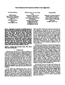
Figure 1. An event sequence graph ESG and ESG as the complement of the given ESG.
Mathematically speaking, an event sequence graph (ESG) is a directed, labeled graph and may be thought of as an ordered pair ESG=(α, E), where α is a finite set of nodes uniquely labeled by some input symbols of the alphabet Σ, denoting events, and E: α Æα, a precedence relation, possibly empty, on α. The elements of E represent directed arcs between the nodes in α. Given two nodes a and b in α, a directed arc ab from a to b signifies that event b can follow event a, defining an event pair (EP) ab (Fig. 1). The remaining pairs given by the alphabet Σ, but not in the ESG, form the set of faulty event pairs (FEP), e.g., ba for ESG of Fig. 1. As a convention, a dedicated start vertex, e.g. [, is the entry of the ESG whereas a final vertex, e.g. ], represents the exit. Note that [ and ] are not included in Σ. The set of FEPs constitutes the complement of the given ESG, which is symbolized as ESG . A sequence of n+1 consecutive events that represents the sequence of n arcs is called an event sequence (ES) of length n+1, e.g., an ES of length 2 is an EP. An ES is complete if it starts at the initial state of the ESG and ends at the final event; in this case it is called a complete ES (CES). Occasionally, we call CES also walks (or paths) through the ESG given. Accordingly, a faulty event sequence (FES) of length n consists of n-2 concluding, subsequent EPs and ends with an FEP. An FES is complete if it starts at the initial vertex of the ESG; in this case it is called faulty complete ES, abbreviated as FCES. A FCES must not necessarily end at the final event. For our experiments, the length of sequences varied from 2 to 4, defining three groups of tests. Those sequences are covered by CESs and FCESs which form test cases to the SUC. A CES is supposed to lead to the exit node. If this is not feasible, the corresponding CES is marked as failed. In contrast, a FCES is not supposed to lead to the final event since this belongs to a FEP which should not be executable. If this is feasible, the corresponding FCES is remarked as failed. For more information on ESG, test case selection, test process, etc. refer to [2, 3, 4, 5, 13].
THEORETICAL BACKGROUND
Formal background of this paper is twofold. Graphbased modeling of SUC to generate and select test cases, and reliability analysis of the data produced by the tests performed using these test cases. Accordingly, the next subsections summarize the basic notions of our research. A. GUI Modeling and Testing with Event Sequence Graphs Basically, an event is an externally observable phenomenon, such as an environmental or a user stimulus, or a system response, punctuating different stages of the system activity. While testing, the test engineer relies on events, which he or she can clearly observe and reconstruct. This is the reason why we favor event-based modeling of SUC.
B. Software Reliability Modeling The SRGMs used in this paper are of type non-homogenous Poisson process due to their flexibility and a well-developed theory behind them. Parameter estimation and the computations of confidence intervals are easily done within this theoretical framework. Following, the notions used are summarized.
403
Definition 1. Let N ( t ) denote the number of random events in the time interval [0, t] . Then
{N ( t ) ,[0, t]}
are known. Note that time-domain data can easily be transferred to interval-domain data but not the other way around. Our approach aims to adopt the parameter estimation for grouped data by building groups of faults detected by their appropriate event sequences with length 2, 3 and 4 instead of time units. The number of test cases for each group will be used as times. This will enable to estimate the expected number of faults for the following to be determined number of test cases and, more generally, for the increase of event sequence length. The estimation of parameters with grouped data is based on the following theorem.
is
called a counting process. Each point of time t, has a random number N ( t ) ∈ ` . A counting process is then said to possess independent increments if the number of events occurring in disjoint time intervals are independent. Definition 2. Let { N ( t ) ,[0, t]} be a counting process. Then N ( t ) is a non-homogenous Poisson process (NHPP) if N (0) = 0 ,
Theorem. Let N ( t ) be as above and t e the end of testing.
b)
N ( t ) has independent increments, and
c)
N ( t + s ) − N ( t ) has a Poisson distribution with
[ t 0 , t1 [ ,..., ⎡⎣ t p −1 , t p ⎡⎣ , t 0 := 0, t p := t e . Assuming that in each interval Ii := [ t i −1 , t i [ the number of observed events is yi
a)
Let the interval [ 0, t e [ be subdivided into p intervals
parameter μ ( t + s ) − μ ( t ) , where μ ( t ) is a differentiable function.
the likelihood function is given by L ( θ1 ,..., θk ) = L ( θ1 ,..., θk ; y1 ,..., y p ; t e ) :=
It is evident that E ( N ( t ) ) = μ ( t ) , where E is the expec-
⎛ p ( μ ( t ) − μ ( t ) ) yi i i −1 = ⎜∏ ⎜ i =1 yi ! ⎝
tation. The function μ ( t ) is called the mean value function.
Its derivative λ ( t ) := μ′ ( t ) is called the intensity function (failure intensity). If the intensity function λ ( t ) = c is a constant, then
(μ ( t ) − μ ( t ))
( ) ( i−1 ) ) . The assumption of indee( i yi ! pendent increments leads to the equation of the likelihood function. Note that a maximum of L can be found, by determining a maximum of its logarithm.
. ⎛ p ⎞ = ⎜ ∑ y i ⋅ ln ( μ ( t i ) − μ ( t i −1 ) ) − ln ( y i !) ⎟ − μ ( t e ) ⎝ i =1 ⎠
(3.3)
So, the maximum can be obtained by solving the system of equations ∂ ln L ( θ1 ,..., θk ) = ∂θ j (3.4) ∂ ⎛ ⎞ μ − μ t t ( ) ( ) ( ) i i −1 ⎜ p ⎟ ∂θ j ⎟ − ∂ μ ( t e ) = 0, j = 0..k = ⎜ ∑ yi ⎜ i =1 μ ( t i ) − μ ( t i −1 ) ⎟ ∂θ j
1) There are several equivalent definitions of NHPP. 2) From the clause a) of Definition 2 we obtain μ (0) = 0 . 3) According to c) of Definition 2 we have the probability P ( N ( t + s) − N ( t ) = k ) = − μ ( t + s ) −μ ( t ) ) ⋅e (
− μ t −μ t
ln L ( θ1 ,..., θ k ) =
Remark.
(μ ( t + s) − μ ( t ))
yi
i −1
i
(HPP). In our case N ( t ) will be the number of failures up to time t of test duration. As a rule of thumb, a HPP can be used if the SUC and its usage are not changed. Any changes to the SUC, such as by correction of faults or its usage, may result in a non-constant failure-intensity function.
=
(3.2)
Proof. The probability that there are yi events in interval I i according to the definition of NHPP is calculated by
μ ( t ) = λ ⋅ t , and N ( t ) is a homogenous Poisson process
k
⎞ ⎟ ⋅ e −μ ( te ) ⎟ ⎠
⎜ ⎝
(3.1)
⎟ ⎠
∎ 1) Software Reliability Models: Next, we proceed to select suitable SRGMs to which the data from [4] can be applied to. Software reliability models of type NHPP are completely specified by defining λ ( t ) or μ ( t ) . The question however is: How are those functions determined? In [20] an approach is presented which allows the derivation of μ ( t ) (and λ ( t ) ) for all NHPP type models as well as the derivation of new models from meaningful assumptions with a very general methodology. In order to form expressions for λ ( t ) and μ ( t ) the function l : ` → \ is consi-
k! NHPP is completely specified by its mean value function or its intensity function. Both normally depend on several unknown parameters ( θ1 ,..., θk ) which have to be estimated on the basis of the underlying data constitution. In real world situations the exact times t1 ,..., t k of events are often unknown, e.g., a software system during test might only have the events (failures) per day and the total amount of testing time for this day (in hours). These are so called grouped data (or “interval-domain data”), in contrast to time-domain data where the exact times of events t1 ,..., t k
404
dered, where l ( n ) is the failure intensity of a software system after detection and correction of failure n. In this general setting the starting point for all software reliability models of type NHPP is a difference equation for l ( n ) that has to
where c :=
λ0
N 0 ⋅ ( N 0 + 1) ⋅ ( 2 ⋅ N 0 + 1)
and
d ( t ) :=⋅ ( 2 ⋅ N 0 + 1) ⋅ ( ec ⋅t − 1) + 1 . 2
be solved. This will result in μ ( t ) as a solution of the dif-
Last, the Duane (D) model is used with μ ( t ) := a ⋅ t b (D) In principle, the Duane model can be also derived from a reduction function.
ferential equation μ ′ ( t ) = λ ( t ) = l ( μ ( t ) ) with its initial
condition μ ( 0 ) = 0 . As an example, the basic execution time model of J. Musa (M for short) can be derived from the difference equation l ( n ) = l ( n − 1) − c, n > 0 ,
λ
0 . Here, λ0 is the failure intensity at the beN0 ginning and N 0 is the total number of failures. The solution of the difference equation with its initial condition l ( 0 ) = λ0
where c :=
is l ( n ) = λ0 − n ⋅ c . Solving the differential equation gives the defining equation for M μ ( t ) = N 0 ⋅ 1 − e − λ0 / N0 ⋅t (M).
(
)
The logarithmic Poisson model of Musa Okumoto (in short MO) can be derived from l ( n ) = c ⋅ l ( n − 1) , 0 < c < 1 , where c is the factor of improvement (typically around 0.9 ∗∗ ). The solution of this difference equation with initial condition l ( 0 ) = λ0 is then l ( n ) = λ0 ⋅ c n . Here, the solution of the corresponding differential equation is 1 μ ( t ) = ln ( λ0θ t + 1) (MO),
Figure 2. Reduction function.
2) Parameter Estimation with Grouped Data: The general formula for parameter estimation of NHPP is given in (3.4). The question is: How good are the estimations if the number of groups is small? This question is decisive for our problem of analyzing the dependency of fault detection on the length of test sequences, because the test process to produce the test data necessary for the reliability analysis is expensive, and thus feasible for a small number of the groups given by the sequence length. The answer is: The better the model fits (e.g., checked via the u-plot with all the exact times of events), the smaller the number of groups can be. See [12] for the uplot. Whenever possible CASRE was used for the u-plot. In all other cases MATLAB was used. To get an impression on what happens in real applications for a number of well known and published data sets (e.g., Musa S1, S2, S3 sets, see [12]), the parameters for several models are estimated first using all data, then decreasing the number of groups. That is several groups were made from the exact failure times. Table I shows the results for some models and the S1 data set. The groups were equally spaced in time. Similar results have been observed with other data sets. With exception of Duane model all models are considerably stable when computed with all data or different numbers of groups. The Duane model has another disadvantage: Its failure intensity at the beginning is infinite. Musa model and qrmodel have the same parameters; however, M is in many cases more optimistic. The estimated number N0 of total faults is increasing all the time during the test period, whereas the estimated N0 is quite stable over time with qrmodel.
θ
where θ = − ln ( c ) is the failure intensity decay parameter. An advantage of M is its simplicity and the importance of its parameters. But in many cases M is too optimistic as removing failures at later stages of testing most often has (on average) less effect on the improvement of the failure intensity as in the beginning. Therefore, in [20] a whole family of models with the same parameters λ0 , N 0 was in-
troduced, where the improvement r ( n ) := l ( n − 1) − l ( n ) was assumed to be a linearly decreasing function and not a constant as in M. These models are called linear reduction models. Next, a model is used where r ( n ) := l ( n − 1) − l ( n ) is a quadratic function that decreases to zero. This model, called qr-model (quadratic reduction model) has the same parameters as M but is much less optimistic. Fig. 2 shows the reduction functions r ( n ) for M, a linear reduction model called lr(0) in [20] and qr. The formula of qr is more complex, but the model has several desirable properties:
(
c⋅ x 1 ( 2 ⋅ N 0 + 1) ⋅ d ( t ) − e ⋅ d ( t ) μ ( t ) := 2 d (t )
) (qr), 405
TABLE I.
Model parameters all data 9 groups 3 groups 2 groups
PARAMETER ESTIMATION FOR GROUPED DATA (MUSA S1 DATA).
M
MO
D
qr
λ0
N0
λ0
θ
a
b
λ0
N0
0.0050 0.0048 0.0047 0.0045
141.98 142.03 142.80 143.58
0.0119 0.0093 0.0101 0.0226
0.0240 0.0220 0.0229 0.0308
0.548 1.092 2.345 8.041
0.484 0.421 0.354 0.247
0.0081 0.0073 0.0101 0.0089
210.50 215.17 219.01 202.11
produced. Thus, the errors reported [4] are permanent ones and have been detected on both platforms (and not on only one stochastically).
IV. CASE STUDIES For our reliability analysis performed in section 5, we conducted two case studies on different systems. The goal of these case studies is to evaluate the analysis results against each other. A. Case Study 1: RealJukebox For the first case study RealJukebox (RJB), more precisely the basic, English version of the RJB 2 (Build: 1.0.2.340) of RealNetworks, has been selected as SUC.
Legend: [: Entry; L: Load a CD; S: Select track; P: Play track; M: Mode; R: Remove CD; ]: Exit
Figure 4. The system function Play and Record a CD or Track represented as an ESG and its complement.
1) Modeling the UI of RJB: In accordance with Fig. 3, the ESG in Fig. 4 represents the top-level GUI to enable the interaction “Play and Record a CD or Track” via the main menu. The user can load a CD, select a track and play it. He or she can then change the mode, replay the track, or remove the CD, load another one, etc. Thus, Fig. 4 illustrates all sequences of usersystem interactions to realize likely operations the user might launch when starting the system. Each of the nodes of an ESG in Fig. 4 represents user inputs which interact with the system, leading eventually to events as system responses that are expected, i.e., correct situations. Thus, each solid arc of the ESG represents a pair of subsequent legal events which was defined as an EP. Accordingly, each dashed arc represents a pair of subsequent illegal events (FEP).
Figure 3. GUI of RJB.
Fig. 3 represents the main menu of SUC that realizes a personal music management system. The user can build, manage, and play his or her individual digital music library on a personal computer. It consists of many window components which can be used to traverse through the entries of the menu and sub-menus, creating many combinations and accordingly, many applications. For this case study, 12 different functions of the SUC were identified, e.g., Play and Record a CD or Track, Create and Play a Playlist, etc. User interactions within a function were modeled by ESGs; their nodes are interpreted as the operations on identifiable objects that can be perceived and controlled by input/output devices. Thus, an event can be a user input as well as a system response that interacts with the next user input, triggering a new output. See [4] for an in-detail description. By means of running the tests on two different platforms, random errors are excluded that cannot be re-
2) Results of The Case Study: The number of CESs and FCESs depends on the extent of the connectivity of the ESG under consideration. In the extreme case, when there is a bi-directional arc between every pair of n nodes and self loops at every vertex, only CESs can be generated, i.e., the set of FCESs is empty. Table II depicts the generated number of test cases for each function sorted by length as well as the number of faults detected subject to their sequence length. It shows that the detected faults by covering ESs of length 2 (forming the group 1) is a subset of the detected faults by covering ESs of length 3 (group 2), which is, in turn, a subset of the detected faults by covering ESs of length 4 (group 4).
406
TABLE II.
NUMBER OF FAULTS AND ADDITIONAL FAULTS DETECTED OVER SEQUENCE LENGTH COVERED FOR RJB.
Length of covered ES
Test Cases
Detected Faults by CES
Detected Faults by FCES
Total nb. Detected Faults
Additional Faults
Fault per Test Case (Efficiency)
2
914
24
20
44
+44
4.8 * 10-2
3 4
2458 6936
24+7
20+5
31+4
25+8
56 68
44+12 56+12
2.3 * 10-2 0.9 * 10-2
TABLE III.
RESULTS ACCORDING TO ISELTA
Length of covered ES
Test Cases
Detected Faults by CES
Detected Faults by FCES
Total nb. Detected Faults
Additional Faults
Fault per Test Case (Efficiency)
2
432
5
22
27
+27
6.3 * 10-2
3 4
1796 8247
5+2 7+0
22+4 26+2
33 35
27+6
1.8 * 10-2 0.4 * 10-2
33+2
It is worth mentioning also that additional 12 transient faults have been found during the testing procedure. These faults have been detected randomly and on only one of the test systems; thus they could not be reproduced on both test platforms. Therefore, they are not included in any of the tables. Table II summarizes also test case costs in terms of the number of test cases and detected faults depending on the event length. B. Case Study 2: ISELTA For a better judgment, we performed a second case study using a large commercial web application with 53K SLOC (source lines of code). ISELTA [23] supports travel agencies, hotels, and touristic enterprises for creating, marketing, and selecting services offered or to be offered by means of comfortable masks. These masks can be embedded in an existing homepage as an interface between customers and system. Potential end customers can then use those masks to select and book services, e.g., hotel rooms, rental cars, etc. A screenshot of the system can be seen in Fig. 5. For this case study, 6 different functions of the SUC have been tested, which implement login, room management, search and booking. Test cases have been executed using Mozilla Firefox Browser Version 3.5. ISELTA itself was installed on a Linux (Debian) version of Apache Web server, configured equally to the “real” server. As in case study 1, detected faults by covering ESs of length 2 is a subset of the detected faults by covering ESs of length 3, which is, in turn, a subset of the detected faults by covering ESs of length 4. Results of the Case Study 2 are summarized in Table III that has significant similarities to the results of the Case Study 1 (Table II).
Figure 5. Screenshot of ISELTA.
C. Tool Support To avoid tedious and error-prone manual work, we developed the tool GATE [4] (Generation and Analysis of Test Event sequences). The tool accepts the adjacency matrix of the ESG and generates test inputs of required length for a given ESG, i.e., ES, FES, CES, and FCES. As a first step, all ESs of a given length are produced. GATE can also generate CESs of a given length which cover all ESs. Furthermore, the tool determines the effectiveness of a given test case in terms of the number of ESs covered. If no length is explicitly given, the tool constructs a CES of minimal length that covers all ESs. For our case studies we used GATE to generate all CESs and FCESs covering the different length of event sequences under consideration.
407
V.
RELIABILITY ANALYSIS OF THE RESULTS OF THE CASE STUDIES
parameters has the same result as simply solving the equations μ ( t1 ) = y1 , μ ( t 2 ) = y1 + y 2 . Table IV shows the results of some of the models deployed (Musa Basic, Musa-Okumoto logarithmic Poisson model, Duane-model and the quadratic reduction model). The estimated parameters are used to predict the expected number of failures μ ( t3 ) for the next (third) interval and a 95% confidence interval ⎡⎣ μl ( t3 ) , μu ( t3 ) ⎤⎦ for the expected number of failures,
A. Analyzing the Results of RJB A common reluctance against software reliability models stems from the assumption of “independent increments” concerned with most of the models. However, thanks to the specific way how we run the tests in our case studies, this assumption causes no problem: Test cases are either complete event sequences (CESs) or faulty complete event sequences (FCESs), which are generated by GATE and then executed randomly. The SUC is restarted after each test execution. Thus, there is no reason why failures should (could) be dependent. The numbers of test cases as discrete time units are used for computation. The grouped data has three groups which are defined by: [0, 914[, [914, 3372[, [3372, 10308[ i.e., “times” t1 = 914, t 2 = 3372, t 3 = 10308 with y1 = 44, y 2 =12, y3 = 12 as failures per interval. Unfortunately, we could not deploy the well-known tool for software reliability estimation CASRE [12] since we have only a small number of groups (2 or 3). The maximum likelihood estimation of the parameters for grouped data was performed with Maple [25] using equation (3.4). Now, we have to answer following question: Is it reasonable to use SRGMs with these data? Following facts help with answering this question. 1) Testing was not conducted according to any usage profile. 2) Faults are not corrected. 3) There are no exact times when failures occurred. 4) There is only a very small number of groups. It turned out, that point 4) somehow compensated the other disadvantages: Within groups it does not matter how testing is done (according to a usage profile or not). Faults are only counted once (assuming they were corrected). As shown before, even a small number of groups allows the estimation of the parameters of the reliability models. In order to keep the computations tractable, only SRGMs of type NHPP were used. As a first step for estimating parameter only the first two groups were used. Hence, having these two groups and models with two parameters the maximum likelihood estimation of the TABLE IV.
Model parameters ML-Estimation
μu ( t 3 )
Figure 6. Mean value function for the models D, MO, qr, and
M; two groups used.
PARAMETER ESTIMATION AND PREDICTIONS WITH TWO GROUPS FOR RJB
M
MO
D
λ0
N0
λ0
θ
0.093
56.20
1.174
0.108
μ ( t3 ) μl ( t 3 )
i.e., the real number of faults will be in this interval with probability of 95%. The lower ( μl ) and upper bound ( μu ) are exact bounds, which can be computed with the defining formula (equation (3.1)) for the NHPP (see [7] for confidence limits). Table IV depicts that D and MO give rather exact predictions of the number of failures after the third interval. The other two models have to be rejected at a significance level of α = 0.05 . The predicted number N 0 of total failures of model M is completely wrong (68 were experienced up to t3 ). The qr-model behaves slightly better. The interesting result is that this model can predict the total number of failures and is considerably less optimistic than M. Fig. 6 illustrates the number of failures and different values of μ ( t ) . From top to bottom (at the right end) we have D, MO, qr and M.
56.2 55.02
b
λ0
N0
12.49
0.185
0.233
70.17
66.31 56.86
60.05
68.83 72.53
408
qr
a
61.84
62.15 75.80
57.34
66.93
As a next step the parameters of the models were estimated via maximum likelihood (see equation (3.4)) using all three groups. The likelihood ⎛ p ( μ ( t ) − μ ( t ) ) yi ⎞ i i −1 ⎟ ⋅ e−μ( t e ) L := ⎜ ∏ ⎜ i =1 ⎟ yi ! ⎝ ⎠ which is the probability of the observed data, given the parameters, and the logarithmic likelihood ln L for the different models are shown in Table V. TABLE V.
Figure 7. Mean value function, for the models D and MO; three groups used
LIKELIHOOD AND LOGARITHMIC LIKELIHOOD OF THREE GROUPS FOR RJB
Model
M
MO
D
L
0.2 ⋅10−7
0.73 ⋅10−3
ln L
-17.756
-7.218
As an example, the Maple code for the maximum likelihood estimation of MO is given as follows:
qr
0.78 ⋅10−3 0.25 ⋅10−3 -7.161
> t:=[0, 914, 3372, 10308]: > y:=[44,12,12]: > p:=3: > mu:=t->1/d*ln(l0*d*t+1): >lnL:=sum(y[i]*ln(mu(t[i+1])mu(t[i])),i=1..p)-mu(t[p+1]): fsolve({diff(lnL,l0)=0,diff(lnL,d)=0} ,{l0=.05,d=.05});
-8.280
As expected from the case of two groups, D and MO are by far the best two predicting models. Table VI shows the results and predictions of the expected number of failures for the next 10000 test cases ( s = 10000 ). The last row shows the predicted 95% confidence limits. TABLE VI.
Model parameter
MO λ0
ML-Estimation μ ( t3 + s)
{ d = 0.1004081850 , l0 = 0.8909283093 }
PARAMETER ESTIMATION AND PREDICTIONS OF THREE GROUPS.
θ
0.890 0.100 74.75
μ l ( t 3 + s ) μ u ( t 3 + s ) 69.70
By setting p:=2 the estimations for two groups can be calculated. The starting values for λ 0 and θ have to be chosen carefully. For example the parameter λ 0 can
D
79.76
a
b
roughly be estimated by λ0 = l ( 0 ) ≈ 44
and θ can 914 first estimating
13.00 0.179 76.78 71.01
roughly be estimated when l ( n ) = 12 and then using l ( n ) = c n ⋅ l ( 0 ) , n = 68 6936 and θ = − ln ( c ) (see (3.3.1)). Another way to get start-
82.51
ing values is via least squares for μ ( t ) which can be easily done with Maple or most statistical packages. The estimation for other models can be done by adjusting the formula for the mean value function μ ( t ) (and the starting values). Another important question was the distinction between CES and FCES: Does the number of failures for ES coverage of length 2, 3 and 4 follow the same distribution? ((24, 7, 4) failures for CES and (20, 5, 8) failures for FCES were observed). A simple chisquare test was used to test the hypothesis: 1) H 0 : (24, 7, 4) and (20, 5, 8) come from the same distribution 2) a) H 0 : (24, 7, 4) comes from the same distribution as (22, 6, 6) (the mean of both experienced). b) H 0 : (20, 5, 8) comes from the same distribution as (22, 6, 6)
Both models predict an actual failure intensity of approximately 0.001 (failures per test case). Fig. 7 shows the failures and the mean value function for MO and D. Predictions of these two models are similar and can be used for the decision whether to stop testing or to continue. This is much better than simply stopping testing until time or money is run out as this effort could have been saved when the fault detection prediction is low. Alternatively, the ratio between new faults estimated and the additional number of test cases could be considered. In Table VI we estimated the expected number of faults within the next 10000 test cases. 6.75 new faults are estimated by MO. If this is not an appropriate outcome, testing can be stopped. Note that, especially for covering event sequences of higher length, the corresponding number of test cases increases enormously. In our case testing was stopped after covering ESs of up to length 4.
409
TABLE VII.
PARAMETER ESTIMATION AND PREDICTIONS WITH TWO GROUPS FOR ISELTA
Model parameters
M λ0
ML-Estimation
0.130
μ ( t3 ) μl ( t 3 )
μu ( t 3 )
MO
33.005 33.005
13.568
33.28
34.05
32.01
λ0
0.122
0.479
39.88 34.78
TABLE VIII.
34.24
44.94
32.564
38.79
LIKELIHOOD AND LOGARITHMIC LIKELIHOOD OF THREE GROUPS FOR ISELTA
M
MO
D
qr
L
0.14*10-4
0,13*10-2
0.10*10-2
0.31*10-2
ln L
-11.186
-6.639
-6.896
-5.770
D
39.10
37.549 35.68
C. Threats to Validity Concerning model-based testing and reliability estimation, there are some threats to validity which should be mentioned. First of all, the results of the case studies and faults found depend on the right specification of the model, i.e., we assume our ESG models to be correct and complete due to the desired behavior. Moreover, the ESG model has the power to detect errors in interaction sequences but not, e.g., in faulty database interactions, i.e., the reliability estimations performed in this paper are really helpful to define the stopping criteria for our ESG methodology. It delivers no conclusion about kind of faults which cannot be detected by ESGs. That's why we excluded random errors in the RJB case study. We wanted to consider reproducible faults that are definitely detected by our ESG model. For our experiments the length of test sequences varied from 2 to 4. This is due to the fact that especially for covering event sequences of higher length, the corresponding number of test cases increases enormously. Moreover, the calculations show that considering sequences of higher length is not reasonable. However, special care is necessary for estimating model parameters. We addressed this circumstance of small number of groups in Section III.B.2.
θ
273.772 0.399 36.68
N0
Model
MO λ0
μl ( t 3 + s ) μ u ( t 3 + s )
12.852
qr
b
PARAMETER ESTIMATION AND PREDICTIONS OF THREE GROUPS FOR ISELTA
Model parameter
μ ( t3 + s)
0.273 43.24
B. Analyzing the Results of ISELTA To strengthen (or falsify) the results of Case Study 1 we carried out a second case study. In analogy to Table IV, Table VII shows the parameter estimations and predictions for ISELTA with two groups. The mean values and confidence intervals are calculated on the basis of the results given in Table III. Again, a 95% confidence interval is calculated with μl as lower bound and μu as upper bound. Following times and failures per interval have been used for computation: [0, 432[, [432, 2228[, [2228, 10475[ i.e., “times” t1 = 432, t 2 = 2228, t 3 = 10475 with y1 = 27, y 2 = 6, y3 = 2 as failures per interval. Obviously, the results of the first case study can be confirmed. Again, the real number of faults (35) lies within the confidence intervals of MO, D and qr. Parameter estimations of MO for two and three groups vary a lot. Estimations of D and especially qr are much more stable. Table VIII shows the likelihood L and the logarithmic likelihood ln L for the observed data. As expected, the qr-model is the best predicting model for ISELTA. Table IX shows the results and predictions of the expected number of failures for the next 10000 test cases ( s = 10000 ). The last row shows the predicted 95% confidence limits. The best of the models predicts at most two new faults for the next 10000 test cases.
ML-Estimation
a
38.66
The resulting p-values are: 0.37 for case 1) and 0.76 for cases 2) a) and b). Thus, no distinction between CES and FCES was made for the computations. The answer to the question above is: Half of the failures came from the coverage of CES; the other half from the coverage of FCES.
TABLE IX.
D
θ
λ0
N0
a
qr b
λ0
N0
16.898 0.079 36.90
0.537
36.656 35.59
34.30
34.05
36.94
410
39.48
VI.
CONCLUSION AND FUTURE WORK
[5]
GUI-testing is a challenging and difficult task and requires specific methods which mostly use input sequences as test data. The cost of the test process depends on the number and total length of those test sequences. Analysis of the prediction of the expected number of failures to be detected (as benefits of testing process) by increasing the length of test sequences is the objective of this paper. The first case study exemplifies and validates the approach. A second case study confirms the findings of the first one. We selected a set of software reliability growth models (SRGMs) and extended them to take the features of GUI into account. The analysis of the results of the both case studies encourages the usage of SRGMs because of following reasons: • It was shown that by far the most failures were found by testing complete event sequences of length two (and three). • The contribution of the longer test sequences was far behind expectation. • Another interesting finding was that the numbers of faults detected by positive and negative testing were very close for all groups, i.e., different lengths of test sequences. • The models can help to decide when to stop testing. Table IV and Table VII show interesting facts about the distributions of faults detected with different length of covered sequences. Our future work aims to optimize the test process by only selectively increasing the length of test sequences for fault-prone functions. Additionally, we want to extend the case study to other SUCs to further check the results of this paper and to make a more generalized answer to the question in the introduction regarding ESGs with different complexities. As a further subject of research work we plan to consider different types and levels of testing, e.g., unit testing, integration testing, etc.
[6]
[7] [8]
[9]
[10] [11] [12] [13] [14] [15]
[16]
[17]
[18]
[19]
[20]
[21]
[22]
REFERENCES [1] [2]
[3]
[4]
P. Amman and J. Offutt, Introduction to Software Testing, Cambridge, UK: Cambridge University Press, 2008. F. Belli, “Finite State Testing and Analysis of Graphical User Interfaces”, Proc. ISSRE’01, IEEE Computer Society, pp. 34–43, 2001. F. Belli and C.J. Budnik, “Test Minimization for HumanComputer Interaction”, Applied Intelligence, vol. 26(2), pp. 161–174, 2007. F. Belli, C.J. Budnik and L. White, “Event-Based Modelling, Analysis and Testing of User Interactions: Approach and Case Study”, Softw. Test. Verif. Reliab., vol. 16 (1), pp. 3–32, 2006.
[23] [24]
[25]
411
F. Belli and M. Linschulte, “On Negative Tests of Web Applications”, Annals of Mathematics, Computing & Teleinformatics, vol. 1 (5), pp. 44-56, 2007. F. Belli and P. Jedrzejowicz, “Software Reliability - Modelling and Optimization”, Journal of Information Processing and Cybernetics - EIK, vol. 9, pp. 133-141, 1988. A. Birolini, Reliability Engineering, 5th ed., Springer, Berlin, 2007. G. V. Bochmann and A. Petrenko, “Protocol Testing: Review of Methods and Relevance for Software Testing”, Softw. Eng. Notes, ACM SIGSOFT, pp. 109-124, 1994. T. S. Chow, “Testing Software Design Modeled by FiniteState Machines”, IEEE Trans. on Software Engineering, vol. 4(3), pp. 178–187, 1978. D.R. Cox and V. Isham, Point Processes, Chapman Hall, 1992. B. Korel, “Automated Test Data Generation for Programs with Procedures”, Proc. ISSTA ’96, pp. 209-215, 1996. M. Lyu, Handbook of Software Reliability Engineering, McGraw-Hill, New York, 1996. A. Mathur, Foundations of Software Testing, AddisonWesley Longman, Amsterdam, 2008. W. Q. Meeker and L. A. Escobar, Statistical Methods for Reliability Data, Wiley, New York, 1998. A. M. Memon, “An Event-Flow Model of GUI-Based Applications for Testing”, Softw. Test. Verif. Reliab., vol. 17(3), pp. 137–157, 2007. A.M. Memon, M. Pollack, and E. M. L. Soffa, “Hierarchical GUI Test Case Generation Using Automated Planning”, IEEE Trans. Softw. Eng., vol. 27(2), pp. 144-155, 2001. J. D. Musa, A. Iannino and K. Okumoto, Software Reliability: Measurement, Prediction, Application, McGraw-Hill, New York, 1987. K. Sabnani and A. Dahbura, “A Protocol Test Generation Procedure”, Computer Networks and ISDN Systems, vol. 15, North-Holland, pp. 285-297, 1998. R. K. Shehady and D.P. Siewiorek, “A Method to Automate User Interface Testing Using Variable Finite State Machines”, Proc. 27th Int. Symp. Fault-Tolerant Computing FTCS, pp. 80-88, 1997. H. A. Stieber, “A Family of Software Reliability Growth Models”, Proc. COMPSAC’07, Workshop Papers, pp.217224, 2007. K. Tai and Y. Lei, “A Test Generation Strategy for Pairwise Testing”, IEEE Trans. on Softw. Eng., vol. 28(1), pp. 109111, 2002. A. Memon and Q. Xie, “Empirical Evaluation of the FaultDetection Effectiveness of Smoke Regression Test Cases for GUI-Based Software”, Proc. of the 20th IEEE International Conference on Software Maintenance, pp. 8-17, 2004. ISELTA (Isik‘s System for Enterprise-Level Web-Centric Tourist Applications), URL: http://www.iselta.com A. M. Memon, M. L. Soffa and M.E. Pollack, “Coverage criteria for GUI testing”. Proc. 8th European software engineering conference held jointly with 9th ACM SIGSOFT International Symposium on Foundations of Software Engineering, pp. 256 – 267, 2001. Maple, URL: http://www.scientific.de