sensor network, process monitoring, health monitoring, dynamic diagnosis .... the end of its execution, every fault-free node knows the identities of all the faulty ...
International Journal of Computer Applications (0975 – 8887) Volume 29– No.7, September 2011
Fault Diagnosis in Wireless Sensor Network using Timed Automata Santi Kumari Behera
Prabira Kumar Sethy
Dr. Pabitra Mohan Khilar
Lecturer NIST, Berhampur,
Engineering Assistant DDK Bhubaneswar
Odisha, India
Odisha, India
Assistant Professor NIT Rourkela Odisha, India
ABSTRACT An important problem in distributed systems that are subject to component failures is the distributed diagnosis problem. In distributed diagnosis, each working node must maintain correct information about the status (working or failed) of each component in the system. In this paper we consider the problem of identifying faulty (crashed) nodes in a wireless sensor network and used timed automata for representation. A fault diagnosis protocol specifically designed for wireless sensor networks is introduced and analyzed using finite automata theory. The protocol is proved to be optimal and energy efficient under certain assumptions. In this paper, we propose a diagnosis algorithm on the basis of diagnosability definitions and theoretical studies developed for timed and hybrid automata. The proposed algorithm has been simulated by using MATLAB and the diagnosis parameters such as diagnosis latency and message complexity.
General Terms Recognition, Security, Algorithms, sensor, automata, wireless sensor network, process monitoring, health monitoring, dynamic diagnosis, network model, unicast, multicast, δ-diagnosabolity, fault-dignosis, timed automata.
Keywords Distributed system, wireless sensor network, fault,Timed automat, Security, Algorithms, sensor, automata, process monitoring, health monitoring, dynamic diagnosis, network model, unicast, multicast, δ-diagnosabolity, fault-dignosis, timed automata
1. INTRODUCTION Sensors integrated into structures, machinery, and the environment, coupled with the efficient delivery of sensed information, could provide tremendous benefits to society [1]. Selecting the optimum sensors and wireless communication link requires knowledge of the application and problem definition. A Wireless Sensor Network (WSN) generally consists of a base station or gateway that can communicates with a number of wireless sensors via a radio link. Data is collected at the wireless sensor node, compressed, and transmitted to the gateway directly. If required we can use other wireless sensor to forward data to the gateway. The development of WSNs was motivated by military application such as battlefield surveillance. They are now used in many industrial and civilian application areas, including industrial process monitoring and control, machine health monitoring [14],
environment and habitat monitoring, health care application, home automation and traffic control [15]. In addition to one or more sensors, each node in a sensor network is typically equipped with a radio transceiver or other wireless communications device, a small microcontroller, and an energy source, usually a battery. A timed automata accepts timed words- infinite sequences in which a real-valued time of occurrence is associated with each symbol [24]. If the event performs a fault event, the diagnoser should detect it after at most n steps, where n has a known upper bound [25]. The timed automaton model, developed by Lynch and Vaandrager, is a labeled transmition system model for components in real-time systems. A timed automaton has timepassage actions, in addition to ordinary input, output and internal actions. Timed automata include “trajectories”, which describe the evolution of the system state during time-passage. The behavior of a timed automaton is describe in terms of time traces, or alternatively in terms of admissible timed traces.
2. RELATED WORKS In 1995, S. Rangarajan and A. T. Dahbura in paper “A Distributed System-Level Diagnosis Algorithm for Arbitrary Network Topology” [2], proposed a distributed algorithm. This algorithm describes how to detect and diagnosing faulty processors in an arbitrary network. A periodic test is performed on one another by Fault-free processors. This algorithm uses parallel dissemination of fault event information to minimize the information latency in the network. In 1998, E. P. Duarte jr and T. Nanya in paper “A Hierarchical Adaptive Distributed SystemLevel Diagnosis Algorithm” [3], proposed a Hierarchical Adaptive Distributed System-Level Diagnosis (Hi-ADSD) algorithm, which is a fully distributed algorithm that allows every fault-free node to achieve diagnosis in testing round. In 2009, P. R. China in the paper, “A New Method for Node Fault Detection in Wireless Sensor Network”[13], proposed an improved DFD algorithm. Wireless sensor networks (WSNs) are an important tool for monitoring distributed remote environments. A durational graph is similar to the durational transition graph defined as the main difference is that in a durational transition graph the invariant sets are not defined, and the guards are rectangular sets defined by limits in Q [4]. The expressive power of durational graph is set between discrete event system (des) where diagnosability verification is in PTIME and timed automata where diagnosability verification in PSPACE since model checking on durational graphs is faster than on timed automata. In 2007, Di Benedetto, M.D., S. Di Gennaro and A. D'Innocenzo, in the paper “Diagnosability verification for hybrid
15
International Journal of Computer Applications (0975 – 8887) Volume 29– No.7, September 2011 automata and durational graphs” [31], A notion of diagnosability for hybrid systems is defined, which generalizes the notion of observability. Here verified diagnosability properties on a timed automaton abstraction of the original hybrid system. Here proposed a procedure to check diagnosability, and show that the computational complexity is in PTIME for the system class of our abstraction, namely for a subclass of timed automata: the durational graphs.
3. TIMED (FINITE) AUTOMATA REPRESENTATION OF DYNAMIC DIAGNOSIS A finite automaton accepts timed words infinite sequences in which a real-valued time of occurrence is associated with each symbol [24]. Since a set of sequence is a formal language, this leads naturally to the use of automata for the specification and verification of systems, because the behavior of the system is a set of execution sequences. We can use the finite automata, leading to effective constructions and decision procedures for automatically manipulating and analyzing system behavior when only the systems are in finite-state. A system is diagnosable if, within a finite-time bound and only using the observable output, it is possible to detect whether a fault occurred, that is if a system execution visits a given faulty subset of the state space.
3.1 Assumptions and notations
denotes the discrete state after k switching and dwelling time in . and t is a clock device.
denotes the
we defined a timed language of executions of the discrete state g is given by ℒ, an example of timed execution ρ Є ℒ is , 3, , 6, … given a subset of discrete states Q* ⊆ Q, we define ℒQ* the language of executions with finite cardinality, such that the last visited discrete state belongs to Q* given an execution = , we introduce the following notations: is the discrete state in the time interval the execution associated to . -
=
,
,… , ,
is the substring of
of
from index I
to j. -
is the time durational of .
In this paper we assume the following: (1) Each node has a unique identifier which can be encoded using log n bits. (2) Each node knows its identifier and the identifiers of its neighbors. This is the only knowledge of the system graph that a node has.
In this paper we modeled the wireless sensor network for diagnosability by graph defining the node connection topology and a timed variable is associated to each node. We assume algorithms work by use of heartbeat messages, i.e., each node periodically initiates a round of message transmission to other nodes in order to indicate that it is working [4]. We call durational graph, a timed automaton characterized by only one clock that is reset to 0 for all edges. The diagnosis problem consists in the identification of the set of faulty nodes in a system. In the distributed version of this problem, diagnosis is achieved by means of a distributed protocol. A distributed diagnosis protocol is said to be correct if it terminates in finite time and, at the end of its execution, every fault-free node knows the identities of all the faulty nodes in the network. A wireless sensor network described by the durational graph g is said to be δ-diagnosable if correct diagnosis is always possible provided the number of faults does not exceed δ. The largest integer δ for which g is δdiagnosable is called the diagnosability of g.
Given a hybrid automaton H, let be a set of disctere states that model a failure in H: is called faulty set. if a system is diagnosable for some finite δ, the following property shows that it is very interesting to compute the minimum value for which H is -diagnosable: given H ,the following statements hold:-
A durational graph [24] can be uniquely identified by a tuple g= (Q, , E, Ψ, η, Inv, G, t);
1. all
Q is discrete space where finite cardinality │Q │= N and initial condition ⊆ Q.
2. for all
Ψ is the finite set of discrete output symbols {Є, Ψ1, Ψ2… Ψr},where Є is the unobservable output that corresponds to the empty string. η: E → Ψ is the output function, that associates to each edge a discrete output symbol. {Invq}qЄQ associates to each discrete state a circular invariant set Invq ⊆ X, and {Ge}eЄE associates to each edge a circular guard set Ge ⊆ Invs(e). Given a durational graph g, we define a timed string ρ as a sequence of pairs with cardinality │ρ │, where
(3) Faults can occur during the execution of the diagnosis protocol. (4) The network topology is not static can be dynamic during the execution of the diagnosis protocol. (5) The communication graph is connected and symmetric.
If
is δ-diagnosable, then it is
- diagnosable for
≤δ. If Qc is not δ-diagnosable, then it is not ≤δ.
-diagnosable
3.2 Network model The system is composed of n sensors, also called nodes, which communicate via radio transceivers. Nodes are homogeneous and equipped with a limited energy supply. Any node in the system is a potential sink, i.e. it can be used by an external operator to access the information gathered by the network. Sensors can be in one of two states: faulty or fault-free. Faulty nodes are unable to communicate with the rest of the system, either due to a crash or to battery depletion. This means that faults are permanent, i.e. nodes remain faulty until they are repaired and/or replaced. Diagnosis algorithm can use either unicast or multicast
16
International Journal of Computer Applications (0975 – 8887) Volume 29– No.7, September 2011 communication. We consider crash faults in nodes. The crash fault assumption is necessitated by use of heartbeat-based algorithm for diagnosis [4]. A δ-faulty execution is a trajectory that enters the faulty set at a certain time instant, and then continues fallowing for a time duration δ [31]. We assume that all transmissions from any node u are Omni-directional. Thus, any message sent by u can be received by any node in its neighborhood, i.e. within its transmitting range. The neighborhood of node u is denoted N (u). The topology of the system can be described as a di-graph G= (V, E), called the communication graph, where V is the set of nodes and E is the set of edges connecting nodes. Given any u,v V, directed edge (u,v) E if and only if v N(u). The set of faulty sensors is denoted F, with |F|=f≥0. Theorem1: Let be the durational graph g= (Q, , E, Ψ, η, Inv, G, t); of a wireless sensor network, and let k(g) be the connectivity of g. The diagnosability δ of G is: Less than k (G), if the diagnosis protocol is initiated on-demand; At most k(G), if the protocol is allowed to start spontaneously. Proof: Assume the diagnosis protocol starts from an initiator node on-demand (e.g. in response to an explicit request of the external operator). If k(G) faults occur, the set of fault-free nodes in the system could be partitioned into several connected components. Hence, fault-free sensors which do not belong to the same connected component of the initiator would never start their diagnosis; thus impairing the conditions for diagnosis correctness. On the other hand, if the diagnosis protocol is allowed to be initiated spontaneously by any fault-free node (e.g. every t seconds), the fault-free sensors in every component will eventually start their own diagnosis, thus allowing a correct diagnosis also when k(G) faults occur. However, if more than k(G) faults occur, there could exist a faulty node which is not adjacent to all the fault-free components, thus impairing the conditions for diagnosis correctness. An execution ρ Є ℒ is δ-faulty if there exists a finite index
,0
≤ ≤ such that: ∀k < , ∉ ;ρ ; Time (ρ ) =δ. For any faulty execution ρ, we use the notation ρ to denote the first faulty state visited by ρ. We define ƒδ the set of all δ-faulty execution, and ƒ= ⋃δ≥0ƒδ ⊆ ℒ the set of all faulty executions. We say that a set is δ-diagnosable for a system H if it is possible to detect within a delay upper bounded by δ whether an execution has visited the faulty set. The Conditions for δ-diagnosabolity has been borrowed from [31]. Condition 1: A set
is δ-diagnosable for H if and only if: )
A set is defined observable for a system H if it is possible to immediately detect using the observable output whether the current discrete state is visiting .
Condition 2: A set
is observable for H if:
(
)
Condition 3: Is observable if and only if
is 0-diangosable.
3.3 Proposed algorithm We assume that our algorithm be initiated by a unique fault-free node, henceforth called gateway nodes which are later became cluster-heads, in response to an explicit request of the external operator. Two types of messages are exchanged during execution: „Hi‟ messages and diagnostic messages. The „Hi‟ message sent by cluster-head u is a pair of identifiers (u,v), where v is the identifier of the node from which u received the first „hi‟ message (u itself if u is the cluster-head). „Hi‟ messages are used to detect faulty nodes. The diagnostic message sent by node u is a pair (u,Qc), where Qc is the set of the identifiers of the nodes currently diagnosed as faulty by node u. Diagnostic messages are used to disseminate the identities of faulty sensors throughout the network. Algorithm: Terminate=false // Boolean expression to terminate the protocol. Repeat { Step1: Sort the node according to their energy level the network. And put these in a descending order in a stack create number of cluster in that network. This is for to found the cluster head node for make them or treat them as gateway. Start diagnosis: R(cluster-head, cluster-head): R is radio range. Step2: User puts request to gateways. The gateway accepts the ping commands from the user. Step3: An initial node gives request to different neighbor nodes. Initial nodes maintain a timer value after sending a request message. Node executes a diagnosis task. Set_timeout(Tout); // the nodes that did not replay within time Tout are diagnosed as faulty. Step4: If node is within range of message to node .
, Then Node
sends a Hi
Step5: After executing a diagnosis task node will compare the result of diagnosis task of itself and request received from . Receive (qi, ); // upon receiving a diagnostic message m, is used to extend the Gateway‟s diagnosis. ) from section 3.2 condition1.
17
International Journal of Computer Applications (0975 – 8887) Volume 29– No.7, September 2011 Step6: If (match occurs) Diagnosis to be fault free. If all fault neighbors sent their diagnosis, the cluster-head‟s diagnosis is complete and is sent to all the fault free nodes in the network using a broadcast protocol. Else Diagnosis to be faulty, if the node is out of range or did not reply within timeout condition.
Theorem 2: Given a durational graph g and a faulty set Qc, it can compute the minimum value δm for which Qc is δm –diagnosable in polynomial time with respect to . The minimum number of bit that exchanged between sensor nodes in Oder to achieve a correct diagnosis is O(n log n + f(n-f)log n).
Step7: Otherwise, node diagnosis node as faulty If (Qc = N(clusterhead)) then //If all of its neighbors are faulty then the diagnosis is complete.
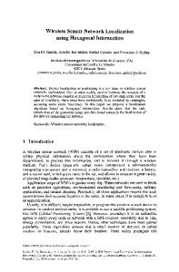
A wireless network can be modeled as set of N nodes and a set of edges connecting the nodes by a radio link. In this section we present the result of our simulation, which we performed in MATLAB to evaluate the efficiency of our algorithm. Here we evaluate the diagnosis latency and the message complexity of our algorithm by MATLAB. Here we take the nodes N= 8 16 32 64. The following graph shows the diagnosis latency and message complexity of the wireless sensor networks. Figure-1 shows the diagnosis latency, the time taken by all the nodes to diagnose an event. When the node increases the diagnosis time also increases. The minimum and maximum message delays, and , are the minimum and maximum times, respectively, between the last bits of a message being injected into the network and the message being completely delivered at a working neighboring node. In our simulation model, each node in the network is a facility. Processes are created to model the execution of the algorithm and also the execution of the normal workload in the node, i.e., processing is not part of diagnosis algorithm execution. Algorithm execution by the node is simulated using a set of delay which is deterministic. Below in figure 2 shows message complexity in time. The total number of message passes through the network to diagnosis which node is faulty and which one is fault-free. If the network increases then the number of message also increases. We use the time event for sending and receiving of messages. Within that time event only the node can send message otherwise the node is found faulty and this information is send to the cluster head and the cluster head will send this message to other cluster head by globally broadcast declared variable. In Figure1 shows the diagnosis latency of our algorithm. When the node increases the diagnosis time increases. We fixed the sending initial time 0.02.
Terminate= true; Endif; } Until terminate;
3.4 Analysis for proposed algorithm Here, we verify the proposed algorithm. A wireless network can be modeled by a set of N nodes and a set of edges connecting the nodes by a radio link. According to our algorithm it take sensor nodes as N= 8 16 32 64 … and it initially arranges the nodes in descending order then it takes nodes as cluster head. The cluster head create a connection between the nodes according to the fixed radio range. We set here a timer for the message sending and receiving from the nodes to the cluster head. at the same time the cluster heads also send their information to the other cluster heads that the nodes are in which state or the status of the nodes. If the node is out of range then also the found as crash faulty or within the certain time if the nodes do not reply what may the reason then the nodes are found as faulty. We consider an abstraction procedure and show that it preserves diagnosability we verify the diagnosability algorithm for both hybrid and durational graphs. We use a super script to refer a language to a system H or g [3]. We proposed a procedure in that takes as input a hybrid automaton H, and produces as output a durational graph g and a relation that associates to each discrete state of H a set of discrete state of g. it was shown that g satisfies the following property. Given H, g and Y, for each execution
=
4. SIMULATION AND RESULT
,
there exists an execution =
such that
, .
Clearly implies inclusion of the language of observations, i.e. in the other words, the behavior of g contains the behavior of H. Assume the reset function of the system H are memory less, i.e. the following holds: . Namely, given an edge e and the corresponding guard set , then each continuous state is non deterministically reset by to a point in the whole range of .
[Figure 1] diagnosis latency of our algorithm
18
International Journal of Computer Applications (0975 – 8887) Volume 29– No.7, September 2011 [7] W. Heinzelman, A. Chandrakasan, and H. Balakrishnan“Energy-Efficient Communication Protocols for Wireless Microsensor Network,” proc. Hawaiian Int’l Conf. on System Science Jan 2000. [8] R. Krishnan and D. Starobinski, "Message-efficient selforganization of wireless sensor networks," in Proc. IEEE WCNC 2003, pp. 1603-1608. [9] F. Kuhn, T. Moscibroda, R. Wattenhofer, "Fault-Tolerant Clustering in Ad Hoc and Sensor Networks," icdcs, pp.68, 26th IEEE International Conference on Distributed Computing Systems (ICDCS'06), 2006. [Figure 2] message complexity of our algorithm algorithm
[10] D. Riordan and S. Sampalli, “Cluster-head Election using Fuzzy Logic for Wireless Sensor Networks”, ISBN: 07695-2333-1, page: 255-260, 2005. [11]
5. CONCLUSION We assumed that our interface with the network is a gateway node that accepts ping commands (control inputs), and replies with pong response after a time delay that we can measure (observed output). We state necessary and sufficient condition for being able to detect which node is faulty and proposed a diagnosis algorithm, on the basis of diagnosability. The definition and theoretical studies developed for timed and hybrid automata in the computer science community. Where the system diagnosability verification is in PTIME and timed automata where diagnosability verification is in PSPACE. We simulate our algorithm by using the MATLAB. Our diagnosis parameters are diagnosis latency and message complexity of the network. When network size increases the diagnosis latency and the message complexity of the network also increases.
6. ACKNOWLEDGMENTS Our thanks to the experts who have contributed towards development of the template.
7. REFERENCES [1] C. Townsend, S. Arms,- Wireless Sensor Networks, MicroStrain, Inc, Chapter 22. [2] S. Rangarajan and T. Dahbura-A Distributed System-Level Diagnosis Algorithm for Arbitrary Network Topologies, IEEE Trans. Computer, Vol.44, No. 2, Feb. 1995. [3] E. P. Duarte Jr. and T. Nanya, “A Hierarchical Adaptive Distributed System-Level Diagnosis Algorithm”, IEEE Trans. Computer., Vol.47, No. 1, Jan. 1998. [4] A. Subbiah and D. M. Blough,” Distributed Diagnosis in Dynamic Fault Environments”, IEEE Trans. Computer, Vol.15, No. 5, May 2004. [5] S. Bandypadhyay and E J Coyle,” An Energy Efficient Hierarchical Clustering Algorithm for Wireless Sensor Networks”, IEEE INFOCOM 2003, vol.3, pages 17131723. [6] B. Das and Bharghayan, “Routing in Ad-Hoc Network Using Minimum Connected Dominating Sets”, in Proceeding of ICC, 1997.
L.Qing, Q. Zhu, M. Wang- Design of a distributed energy-efficient clustering algorithm for heterogeneous wireless sensor networks, Computer Communication, pp2230-2237, 2006.
[12] G. S. Tomar, S. Verma- Dynamic Multi-level Hierarchal Clustering Approach for Wireless Sensor Network, proceeding of the UKSim 2009: 11th International Conference on Computer Modeling and Simulation, pp563-567, March 2009 [13] P. R. China, “A New Method for Node Fault Detection in Wireless Sensor Networks”, ISSN 1424-8220, page: 12821294, 2009. [14]
W. Qiu, E. Skafidas, P. Hao, Enhanced tree routing for wireless sensor networks, Ad Hoc Networks, Vol-7, no. 3, pp. 638-650, May 2009.
[15] A. Tiwari, P. Ballal and F. L. Lewis- Energy-Efficient wireless Sensor Network Design and Implementation for Condition-based Maintenance, ACM Transactions on Sensor Networks(TOSN), Vol-3, no. 1, PP-1-es, March 2007. [16] Z. Xiaorong, S. Lianfing- Near Optimal Cluster-Head Selection for Wireless Sensor Networks, journal of Electronics, Vol-24, no.-6, November 2007. [17] S. Fazackerley, A. Paeth, R. Lawrence- Cluster Head Selection using FR Signal Strength, in proceeding: CCECE’09 Candian Conference On Electrical and Computer Engineering, pp-334-338, 2009. [18] H. Abusaimeh, S. H. Yang- Dynamic Cluster Head for Lifetime Efficient in WSN, in proceeding International Journal of Automation and Computing, pp-48-54, February 2009. [19] H. Munaga, J. V. R. Murthy, N. B. Venkateswarlu- A Novel Trajectory Clustering Technique For Selecting Cluster Heads In Wireless Sensor Networks, in proceeding: International Journal Of Recent Trends In Engineering, Vol-1,no. 1, May 2009. [20] X. Sheng, S. Papavassiliou, L. Zakrevski- Fault-Tolerant Cluster-Based Routing Approach In Wireless Mobile Ad Hoc Networks, in proceeding: 54th conference of IEEE VTS on Vehicular Technology, Vol-4, PP-2613-2617, 2001
19
International Journal of Computer Applications (0975 – 8887) Volume 29– No.7, September 2011 [21] K. Romer, F. Mattern- The Design Space of Wireless Sensor Networks, IEEE Wireless Communications, Vol-6, PP-54-61, December 2004. [22] F. Laroussinie, N. Markey, and P. Schnoebelen. “Efficient timed model checking for discrete-time systems”. Theoretical computer science, 353(1-3):249-271, march 2006. [23] G. S. Tomar and S. Verma, “Dynamic Multi-level Hierarchal Clustering Approach for Wireless Sensor Networks”, IEEE 2009. [24] R. Alur, D. L. Dill- A Theory of Timed Automata, In proceeding of the 17th international colloquium on Automata, Languages, and Programming(1990), and in the Proceeding of the REX workshop “Real-time: theory in practice(1991)”, vol-126, no.2, pp- 183-253, April 1994. [25] R. Alur, C. Courcoubetis, T. A. Henzinger and Pei-Hsin Ho- Hybrid Automata: An Algorithmic Approach to the Specification and Verification of Hybrid Systems, INPROCEEDINGS:Alur92 hybrid automata, pages-209-229,Springer-Verlag,1992. [26] S. Tripakis, Fault Diagnosis for Timed Automata, Springer Berlin/Heidelberg, vol- 2469, pp-205-221, Lecture Notes in Computer Science, January 2002. [27] Di Benedetto, M. D., S. Di Gennaro and A. D'Innocenzo (2005). Error detection within a specific time horizon and application to air traffic management. In: Proceedings of the Joint 44th IEEE Conference on Decision and Control
and European Control Conference (CDC-ECC'05), Seville, Spain. pp. 7472-7477. [28] A. D‟Innocenzo, M. D. Di Benedetto, S. Di Gennaro, Obserable of Hybrid Automata abstraction, In J. Hespanha and A. Tiwari, editors, Hybrid System: Computation and Control, Vol-3927 of Lecture Notes in Computer Science, PP-169-183, Springer Verlag, 2006. [29] F. Laroussinie, N. Markey, P. Schnoebelen- Efficient Timed Model checking for discrete-time systems, Theoretical Computer Science, Vol-353, pp-249-271, march 2006. [30] Di Benedetto, M. D., S. Di Gennaro and A. D'Innocenzo (2006b). Critical states detection with bounded probability of false alarm and application to air traffic management. In: Proceedings of the 2nd IFAC Conference on Analysis and Design of Hybrid Systems (ADHS), Alghero, Sardinia, Italy. [31] Di Benedetto, M.D., S. Di Gennaro and A. D'InnocenzoDiagnosability verification for hybrid automata and durational graphs. In: Proceedings of the 46th IEEE Conference on Decision and Control. New Orleans, Louisiana, USA, December 2007. [32] D'Innocenzo, A., M. D. Di Benedetto and S. Di Gennaro (2006). Observability of hybrid automata by abstraction. In: Hybrid Systems: Computation and Control (J. Hespanha and A. Tiwari, Eds.). Vol. 3927 of Lecture Notes in Computer Science. pp. 169-183. SpringerVerlag.
20