and have protected a software-based fault-tolerant clock synchronisation ... negligible network bandwidth. 1. ..... X-View monitoring software, and a three-.
iCC 2003
CAN in Automation
Fault-Tolerant Clock Synchronisation with MicrosecondPrecision for CAN Networked Systems Dongik Lee, Jeff Allan A fault-tolerant clock synchronisation technique is presented. In a distributed system the discrepancy between a node’s view of current time and the rest of a system can cause critical deadlines to be missed. It may also be the cause of many unknown system errors. In fact, many real-time applications, such as redundancy management, synchronous data acquisition and simultaneous triggering of actuators at several nodes, are impossible without such a global reference time. DRTS Ltd have developed and have protected a software-based fault-tolerant clock synchronisation technique for broadcast networks such as CAN. It provides a predictable and reliable service that enables networked system synchronisation to micro-second precision using negligible network bandwidth.
be missed leading to system failure. It may also be the cause of many unknown system errors.
1. INTRODUCTION Distributed real-time systems are now found in many industrial fields, such as process automation, oil and gas production, and automobiles. However, distributed environment presents significant challenges to the system designers: •
•
In this paper, a software-based faulttolerant clock synchronisation algorithm for CAN networked systems is presented. The proposed algorithm is based on a masterslave structure and the well-known a posteriori technique (Gergeleit & Streich, 1994). The proposed algorithm deterministically guarantees an upperbound for the clock skew and the number of messages required for synchronisation. The key advantage of the proposed method is the capability to tolerate faulty master clocks in a systematic and predictable way.
Communication networks inevitably introduce delays due to limited bandwidth and overhead; and It is difficult to achieve synchronised temporal behaviour a n d data consistency between computing nodes which are physically separated.
The key to solving these problems is the unification of the various representations of time across the system. For example, the former problem can be solved by using time-triggered communication protocols, such as TTCAN and TTP/C, where synchronised clocks are the fundamental requirement.
2. THE BENEFITS OF SYNCHRONISED CLCOKS The benefits of synchronised clocks for commercial computer networks, such as financial transactions and stock trading, have been understood well. Skoog (2001) described clock synchronisation as "a key factor in success or failure of a networked system". As a result, most of computer networks are equipped with time servers and synchronisation algorithms, such as Network Time Protocol (NTP).
The quartz oscillators used in computers and networking equipment change with age and are affected by environmental variables, such as mechanical vibration and temperature. Consequently, clocks can drift up to several seconds per day. The discrepancy between a node’s view of current time can cause critical deadlines to
Clock synchronisation techniques are also beneficial for many industrial applications: 07-1
iCC 2003
CAN in Automation
Time-Triggered Communications In safety-critical applications, such as Xby-wire cars, randomly varying message latency causes significant concern. In response to this concern, time-triggered protocols based on scheduling of the communication resources are becoming a common solution for safety-critical and hard real-time systems. For the correct operation of a time-triggered network, it is essential to provide a system-wide time reference to enable a consistent identification of the time at which timeslots trigger.
3 . AN OVERVIEW OF CLOCK SYNCHRONISATION TECHNIQUES
Control Systems A distributed control system may suffer significant time-varying delays (i.e., jitter) between the sampling of the sensors and the reaction of the actuators. This jitter influences the system’s stability as well as changes the system characteristic into a time-varying one for which theoretical results for time-invariant systems cannot be used. A main cause for the jitter is polling of the sensors by the controller (Eidson & Cole, 1998). Using synchronised clocks the control objective can be achieved at a lower sampling rate and communication bandwidth.
•
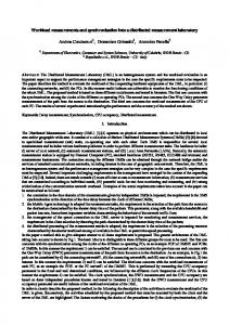
3.1. Clock Synchronisation Blocks Clock synchronisation is a technique to generate an approximate system-wide time reference, the so called “approximate global time”, using local clocks, so that at any instant any two non-faulty clocks agree on the current time within a known bound. Several researchers (Schneider, 1986; Anceaume & Puaut, 1998) stressed that any software clock synchronisation algorithms consist of the three blocks for:
•
•
The detection of resynchronisation time—to trigger each node to start the clock synchronisation algorithm; Reading remote clock values—to obtain information about the remote clock values; and Clock correction—to establish an approximate global time reference, and to calculate the correction term.
A clock synchronisation algorithm having these three blocks can be implemented as in figure 1, where Fc is a “convergence function” to bring clocks closer together. adj kp+1 is the amount by which the
Redundancy Management In safety-critical applications, some degree of hardware redundancy is commonly used to meet the system requirement. Usually, the redundancy management strategy is based on a voting mechanism requiring high degree of data consistency. Without synchronised clocks, voting cannot work properly.
requesting clock p differs from correct value at the resynchronisation round of (k+1). Different choices for these blocks result in different clock synchronisation algorithms. For the surveys on various techniques to implement these blocks, see Schneider (1986), Ramanathan et al (1990), and Anceaume & Puaut (1998).
Synchronous Data Acquisition The existence of global time reference is the fundamental requirement for data acquisition systems (DAQs) for distributed environment. For instance, many DAQs use timestamps to induce a total ordering on the events that occur at different nodes. If the clocks in the system are not synchronised, it is possible for the event to be seen as like affected by the causes from the "future".
k=0; adjp0=0; do forever detect resynchronisation event at time Rk+1; adjpk+1= Fc(p,x1k+1,..., xNk+1) - p; k=k+1; end Figure 1. Clock synchronisation blocks.
07-2
iCC 2003
CAN in Automation
3.2. CAN-Based Algorithms Different clock synchronisation algorithms can be designed according to the network used. CAN has a number of unique characteristics. In particular, a set of error handling facilities and simultaneous delivery offer the potential for achieving precise clock synchronisation. On the other hand, it has relatively low bandwidth which favours simple algorithms. round (k-1)
Master Clock
Tx Tm ,1
k −1
k −1
Tm,1k
mk-1 Slave Clock
Rx k −1
Ts ,1
The a posteriori technique proposed by Verissimo & Rodrigues (1992) has also been applied to CAN networked systems (Rodrigues et al., 1998). This algorithm is based on a fully distributed structure which is inherently fault-tolerant. However a drawback is the complexity resulting from the distributed structure. The number of messages required is N(N+2) for an Nnode system.
round k
Tx
Timestamp Tm, 2
Streich (1994). In each resynchronisation round a different clock is designated as the master, and then the other clocks synchronise to the selected master. However, it uses no mechanism to detect faults in the current master. In addition, if f successive clocks are faulty, then the system can be left without synchronisation during the period of fR.
Timestamp Tm ,2
k
Local Time
mk Rx
Timestamp Ts ,2 k −1
Ts,1
k
Timestamp Ts ,2
k
Local Time
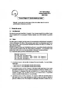
Figure 2. Clock synchronisation based on the a posteriori technique.
4
Gergeleit & Streich (1994) proposed a clock synchronisation technique based on a master-slave structure and a simplified “a posteriori” agreement technique (see figure 2). A clock in the system is designated as the master, which periodically broadcasts a synchronisation message that provides a reference time value. In this method, timestamps are taken right after a message is delivered, rather than before broadcasting the message. In the synchronisation round k, the master broadcasts a synchronisation message m k which contains its timestamp taken at Tmk,−21 when the previous
F. A U L T - T O L E R A N T CLOCK SYNCHRONISATION FOR CAN NETWORKED SYSTEMS
As discussed in the previous section, a major concern with typical synchronisation algorithms for CAN is the vulnerability to a faulty master clock. This section describes a novel CAN-based clock synchronisation algorithm which is capable of tolerating faulty clocks with relatively simple structure.
Table 1. Summary of CAN properties relating to the clock synchronisation (taken from the work by Rodrigues et al., (1998).
synchronisation message m k −1 was delivered to the slaves. Every slave in the system simultaneously receives this message at Tsk, 2 , and takes a timestamp right after the reception. Each slave clock then calculates a correction term using the difference between the timestamps Tsk, 2−1
A1: Validity—If a correct node broadcasts a message, then the message is eventually delivered to a correct node. A2: Best-effort agreement—If a message is delivered to a correct node, then the message is eventually delivered to all correct nodes, if the sender remains correct. A3: Simultaneous agreement—If the sender remains correct, the last retransmission of the same message is delivered to all correct nodes at real time values that differ, at most, by a known interval.
and Tmk,−21 . The key advantage is the high precision that does not depend on message latency. However, the lack of capability to tolerate a faulty master is the major concern. Eriksson et al. (1996) proposed a tokenbased approach to provide a faulttolerance capability with Gergeleit & 07-3
iCC 2003
CAN in Automation
4.1. CAN Properties and Assumptions The algorithm is based on the CAN properties in table 1. These properties, which are achieved by the built-in error handling mechanism of the CAN protocol, provide fault-tolerant broadcast. That is, within a CAN network a message is accepted either by all nodes or by no node. Property A3 is crucial for achieving a high precision of synchronisation using the a posteriori technique. Properties A2 and A3 remove the possibility of Byzantine faults.
with the size of the multiple-master cluster. The larger size of the multiple-master also leads to the higher complexity in the selection mechanism, which is not desirable.
Substitutes Group
4.2. Outline of the Proposed Algorithm The main feature of the proposed algorithm is outlined as follow:
Master Candidates Group (MCG)
Slave Clocks
Figure 3. Subsets of clocks in the system. Substitutes Group
Centralised structure: A master-slave structure is employed in order to create as simple algorithm as possible. The masterslave structure can drastically reduce the number of messages if a broadcast network is used.
CNs+3 C4 CNs+2 C5 C6 C7
faulty
C2 C3 C1 Master Candidates Group (MCG)
Figure 4. Replacement of a faulty candidate clock.
Multiple-master: A multiple-master method is used to tolerate a faulty master. The novelty of the suggested method lies in the use of two groups of master candidates—‘Master Candidates Group’ (MCG) and ‘Substitutes Group’—to reduce bus traffic caused by a master selection process.
In this work, to overcome these problems, all clocks in the system are divided into three subsets (figure 3). At each synchronisation round, only clocks in the MCG take part in the selection of a master. Clocks in the substitutes group do not take part in the selection, and are only for replacing faulty clocks in the MCG. The rest of the clocks in the system are considered to be slaves, which have to synchronise to the selected master clock and are not required to broadcast any message for clock synchronisation.
Resynchronisation detection: A start message is used for triggering a synchronisation round. Clock correction: All clocks in the system synchronise to the time of a selected master clock. The a posteriori technique is used.
An example given in figure 4 explains how the MCG and the substitutes group work in order to update the MCG. Each node of the MCG examines its clock value by comparing with the current master clock time. When a clock in the MCG is found to be faulty, a non-faulty clock in the substitutes group becomes a new member of the MCG. In figure 4, for example, the faulty candidate C 3 is replaced with C4 .
4.3. Subsets of Clocks in the System The major drawback with a multiplemaster technique is the need for a master selection mechanism. Selection algorithms are usually complicated and introduce extra loading on the system in terms of the number of messages and the processing time. The number of messages required for the selection mechanism increases 07-4
iCC 2003
CAN in Automation tolerance using a simple selection mechanism and a lower number of message exchanges.
Clock C 3 takes the place of C4, rather than being removed from the system. The number of clocks for each group can be chosen by the system designer to achieve the desired level of faulttolerance. The size of MCG to tolerate f m faults is given by
N m = 2 fm + 1
4.4. Master Clock Selection Figure 5 shows the entire steps for the suggested algorithm. It is assumed that at most f m = 1 new faulty clock can be found in the MCG in a single synchronisation round, and thus three clocks (C1 , C2 and C 3 ) for the MCG are needed. In this example clocks C1 and C3 are assumed to be the best and the faulty, respectively. Arrows represent a broadcast of message with unknown latency.
(1)
Note that f m denotes the maximum number of new faulty clocks of the MCG that can arise in a single resynchronisation round. Thus, the complexity of the selection mechanism is not directly proportional to the total number of faulty clocks assumed in the system. On the other hand, the size of the substitutes group, N s , depends on the total number of faulty clocks, f, to be tolerated in the system. It seems useful to choose N s as a multiple of f m , to achieve η-modular set of redundant clocks to substitute for faulty master candidates; that is,
N s = ηf m , η = 1,2,...
Selecting a master is performed in the first two steps of figure 5. The selection function (Fv) is based on the timestamps (T1, T2, T3) taken by each candidate clock on the arrival of a start message (mstart). The CAN properties described in table 1 guarantee that all the candidates receive the start message simultaneously. As soon as a timestamp has been taken, each candidate, including the sender of start message, broadcasts a time message that contains its timestamp, and then waits for other candidate’s time messages. According to A2 in table 1, all the correct candidates will obtain an
(2)
Since f m