5th Slovakian-Hungarian Joint Symposium on Applied Machine Intelligence and Informatics January 25-26, 2007 ░ Poprad, Slovakia
Fault Tolerant Computer System Based on TMR Architecture Liberios Vokorokos, Branislav Madoš, Jan Perháč Department of Computers and Informatics, Technical University of Košice Letná 9, 042 00 Košice, Slovakia
[email protected],
[email protected],
[email protected]
Abstract: Article deals with description of fault tolerant computer system based on TMR architecture, designed on the Department of Computers and Informatics of Technical University of Košice as part of the VEGA projects No. 1|1064|04 and 1|4071|07. Article describes basic architecture of system and details of majority element function execution, communication of system modules and synchronization of client‘s applications execution on system modules. Keywords: FTC, Fault Tolerant Computing, TMR, Triple Modular Redundancy, Static configuration redundancy
1
Introduction
Fault tolerant systems are very important for many industry and economy segments that are increasingly dependent on reliability of computer systems operation. There is possibility to reach enhancement of reliability of computer systems operation by fault tolerance implementation. System is considered as fault tolerant in the case of proper function execution capability under conditions of fault occurrence in hardware or error occurrence in software. There is no possibility of fault tolerance against arbitrary type of fault or error or arbitrary quantity of them. It is possible to use reservation of subsystems to increase fault tolerance. It is possible to divide reserves with regard on character of reserve into hardware, software and information reserves. In accordance with use of reserves we can use division to static, dynamic and hybrid reserves. In accordance with equality of reserve and reserved subsystem we can use division into configuration and functional reservation. Most common type of reservation in the case of functional units is static configuration redundancy with use of Triple Modular Redundancy (TMR). TMR system consists of three identical modules, with equal function. Output of each module is evaluated with majority element. In accordance with this we designed architecture of fault tolerant system on TMR
41 ░
L. Vokorokos et al. Fault Tolerant Computer System Based on TMR Architecture
architecture basis on the Department of Computers and Informatics of Technical University of Košice as part of the VEGA projects No. 1|1064|04 and 1|4071|07.
2
Architecture of Designed Computer System
Designed computer system is dedicated to process client’s software applications in C language for Windows operating system in fault tolerance mode. The term client’s application is reserved for software programmed by user of designed computer system with respect to conditions which are required to use system in fault tolerance mode. The design is aimed to use Triple Modular Redundancy (TMR) and personal computers serving as modules. Another goal is to design architecture in the way in which applications not programmed for use of this computer system can be easily and quickly rewritten for adaptation with as low obligatory changes as possible. Designed architecture can operate in three different modes – fault tolerance mode, diagnostic mode, and normal mode, in which system cannot mask faults or to recover after fault occurrence.
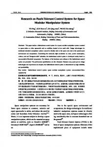
Figure 1 Schema of designed system with triple modular redundancy with tripled majority element
Designed computer system uses three identical modules. Each module is realized as a personal computer. Modules, labeled F1, F2 and F3 in Figure 1, are performing the same algorithm of client’s application. Outputs of modules are
░ 42
5th Slovakian-Hungarian Joint Symposium on Applied Machine Intelligence and Informatics January 25-26, 2007 ░ Poprad, Slovakia
inputs of majority element. To reach more reliable design, function of majority element is tripled and is performed by majority elements M1, M2 and M3. Another step for more reliable computer was made when functionality of majority elements M1, M2 and M3 were transferred into PC modules. Majority element. The function of majority element is to determine majority element output from outputs of computer system modules. Output value of module consists of 8 bits vector. Output value of majority module also comprises of 8 bits vector. The function of majority element is to decide which output of three modules can be used as the output of majority element (Table 1). Equality of outputs of each pair is considered as a vector of bits. Comparison of modules outputs
Possible outputs of majority element
A = B, A=C, B=C
A,B,C
A=B, A ≠ C, B ≠ C
A,B
A=C, A ≠ B, C ≠ B
A,C
B=C, B ≠ A, C ≠ A
B,C
A ≠ B, A ≠ C, B ≠ C
SO Table 1
Output of majority element is dependent on outputs of modules
The value of safe output (SO), is defined by programmer of client’s application and majority element outputs this value in case there are no two equal outputs of modules so majority element cannot decide which of modules output can be used as the output of majority element. Function library. To allow client’s applications to use designed computer system it is necessary to use library of functions, which is part of computer’s design. Functions allows to synchronize start and performance of client’s applications copies on each of modules of designed system, allows communication between modules, performs majority element function on each module and produces and writes output and diagnostic information into output and diagnostic files. Communication between modules. Communication between each pair of modules is performed during computer’s operation. Parallel ports of personal computers, labeled as LPT0 and LPT1 on Figure 2, are used. Communication is important to synchronize software applications on modules of the system and to exchange output information between modules to perform function of majority element.
43 ░
L. Vokorokos et al. Fault Tolerant Computer System Based on TMR Architecture
Figure 2 Schema of system modules interconnection
Synchronization of modules is performed when computer system is starting client’s application. Each of modules outputs predefined information and is waiting for the same information from another two modules of the system. In moment when all three modules obtain information from another two modules, modules are synchronized. Output information is transferred from system module to another two modules of the system, and serves as input information for majority element which function is performed by system module. Output information of module consists of two 8 bits vectors. First of vectors is identification stamp; second vector is value of output. Output values of majority elements are used as inputs for modules or as outputs of the system. System outputs are stored in output files in each module of the system.
2.1
Synchronization of Modules
Schema of synchronization of designed system can be seen in Figure 3. After operator’s manual initialization of a copy of client’s application on each system module (I), which period of time is equal on each module A, B and C, but starts in different moments, synchronization of modules starts (SS). Synchronization starts in different moments in time, but ends at the same time on each module, so the work of modules is synchronized. After the synchronization, synchronized blocks of application (SB1 to SB4 on Figure 3) are performed. The client’s application ends with stop function (ST).
░ 44
5th Slovakian-Hungarian Joint Symposium on Applied Machine Intelligence and Informatics January 25-26, 2007 ░ Poprad, Slovakia
Figure 3 Timeline of client’s application performance on each system module
Application is defined as a sequence of synchronized blocks. Each of blocks starts with use of synchroblock function (SB), performs client’s algorithm (CA) and ends with use of function, which performs majority element function execution (CHK). There is period of time in which all of synchronized block work must be done. The author of client’s application defines this time period. In the case, there is a time reserve in synchronized block, system fills this time with waiting cycles (W). See Figure 4. SB and CHK functions are tied together with time stamp, which is defined by program’s author.
Figure 4 Timeline of synchronized block of client’s application
3
Verification of Architecture
Very important task is to verify reliability of designed architecture and to test fault tolerance of the architecture. Tests were performed to approve: •
Ability of long-time synchronized work of TMR modules.
•
Occurrence of faults within operation of computer system in expected environment of service.
45 ░
L. Vokorokos et al. Fault Tolerant Computer System Based on TMR Architecture
•
Ability of proper function execution under conditions of fault occurrence in hardware or error occurrence in software.
Series of tests were performed in real operation and in operation with simulations of faults. Faults were simulated with special software applications, with predefined different outputs for each of modules and with hardware simulated faults, where communication channels between modules were mechanically interrupted. Basic information about some performed tests is summarized in Table 2a. Operation time of each test is time in which all synchronized blocks of software application were performed. In each test all synchronized blocks were performed and operation of all three modules was completely synchronized. Test
Operation time
Synchronized blocks [Number]
1
7h 32min
1000
2
16h 48min
2000
3
15h 0min
2000
4
22h 25min
3000
5
20h 12min
3000 Table 2a
Basic parameters of performed tests
Test applications were designed to verify ability to mask fault occurrence in one of modules or to recover system after occurrence of faults in two modules. In synchronized blocks of applications different outputs were generated. In some blocks only one module generated different output, in another blocks two modules generated different outputs. Conclusions of tests are summarized in Table 2b. Test
Faults [Number]
Masked [Number]
Double faults [Number]
Safe outputs [Number]
1
250
250
200
200
2
250
250
500
500
3
250
250
500
500
4
1000
1000
250
250
5
1000
1000
250
250
Table 2b Software simulated faults in modules of computer system
Hardware simulations of faults were performed through the interruption of communication channels to perform simulation of faults in one or two modules of system. Conclusions of tests are summarized in Table 2c.
░ 46
5th Slovakian-Hungarian Joint Symposium on Applied Machine Intelligence and Informatics January 25-26, 2007 ░ Poprad, Slovakia
Test
Faults [Number]
Masked [Number]
Double faults [Number]
Safe outputs [Number]
1
78
78
53
53
2
157
157
246
246
3
243
243
313
313
4
228
228
126
126
5
346
346
212
212
Table 2c Hardware simulated faults in modules of computer system
Conclusions The aim of the project of fault tolerant computer system on the Department of Computers and Informatics of Technical University of Košice as part of the VEGA projects No. 1|1064|04 and 1|4071|07 is to analyze possibility of fault tolerance increase of computer system with use of TMR architecture with personal computers in the role of TMR modules. Another aim is to design hardware and software of the architecture. The crucial part of effort is the ability to synchronize operation of modules and to maintain reliable communication between modules. The conclusions of realized tests approved the ability of system to operate properly in conditions of fault occurrence. References [1]
VOKOROKOS, L.: Diagnosis of Fault Tolerant Compound System Using the Observer and Parallel Computer System, Transactions of the VŠT Technical University Ostrava, 2005, pp. 68-76, ISSN 80-248-0358-5
[2]
VOKOROKOS, L.: Parallel Computations for Fault Tolerant System Using Observer, 2nd Slovakian-Hungarian Joint Symposium on Applied Machine Intelligence, Herľany, Slovakia, January 16-17, 2004, pp. 37-41, ISBN 963 7154 23 X
[3]
VOKOROKOS, L.: Parallel Computing Recovery for Fault Tolerant Systems, International Conference in Memoriam John von Neumann, December 12, 2003, Budapest, HU, 2003, pp. 13-22, ISBN 9637154213
[4]
HLAVIČKA, J., RACEK, S., GOLAN, P. et al.: Číslicové systémy odolné proti poruchám, Praha : ČVUT, 1992. 330 p.
[5]
BAČA, J.: Spoľahlivosť a diagnostika, 2. prepracované vydanie. Bratislava: Alfa, 1989. 176 p. ISBN 80-05-00429-X
[6]
BLATNÝ, J., DRÁBEK, V.: Standardizace číslicových rozhraní, 1. vyd. Brno : MON 1990. 302 s.
Supported by VEGA Project No. 1|4071|07
47 ░