exists a distance-decreasing path towards the destination (also see Definition 1). ...... Therefore it is less likely that a routing void will occur, a situation in which.
Fault-tolerant Greedy Forest Routing for Complex Networks Rein Houthooft, Sahel Sahhaf, Wouter Tavernier, Filip De Turck, Didier Colle, Mario Pickavet {rein.houthooft, sahel.sahhaf, wouter.tavernier, filip.deturck, didier.colle, mario.pickavet}@intec.ugent.be Department of Information Technology (INTEC), Ghent University - iMinds Gaston Crommenlaan 8, 9050 Gent, Belgium
Abstract—Geometric routing has been proposed in literature as a memory-efficient alternative to traditional lookup-based routing and forwarding algorithms. However, existing geometric routing schemes lack the ability to address network link and node failures in a natural way, while maintaining a low path stretch. The main contribution of this paper is a novel routing scheme called Greedy Forest Routing (GFR) based on the principles of geometric routing. By employing a graph embedding based on low-redundancy spanning trees, its fault-tolerant characteristics are enhanced. Using a multi-dimensional tree embedding enables natural traffic redirection while still attaining a low average hop count. Index Terms—geometric routing; fault-tolerance; forest routing
However, how low path stretch3 and fault-tolerance can be effectively combined in geometric routing remains largely unsolved. This paper investigates how geometric routing can combine low path stretch with reliable routing behavior. The main contribution is a geometric routing scheme called Greedy Forest Routing (GFR) which ensures a 100% packet delivery success rate. Furthermore it is highly resilient towards node and link failures by utilizing a multi-dimensional embedding based on low-redundancy4 spanning trees. GFR is applicable to a wide range of network types, but is designed with scale-free complex networks in mind. II. R ELATED WORK
I. I NTRODUCTION For over a decade, geometric routing algorithms are emerging as an alternative to lookup-based routing schemes. Though they were originally designed for ad-hoc wireless networks and wireless sensor networks (WSNs) [1], researchers have demonstrated their applicability to wired networks as well [2]. This entails a different design approach because wired networks are generally modelled as scale-free graphs1 rather than unitdisk graphs (UDGs)2 . Geometric routing makes use of a graph embedding in which every network node is assigned coordinates corresponding to a point in a mathematical space. Using these coordinates, and a distance function, packets are routed towards the destination by following a distance-decreasing path. In geometric routing a node only requires information about its local neighbourhood rather than the whole network. Therefore an advantage over a lookup-based approach is their capability of generating routing paths with limited router memory overhead. On the other hand, a clear disadvantage is the lack of routing fault-tolerance because the underlying embedding may lose its greedy characteristics upon the occurrence of network failures. This means that there no longer exists a distance-decreasing path towards the destination (also see Definition 1). Traffic redirection in case of failures is deemed essential in many large-scale communication networks. 1 In scale-free networks the degree distribution follows a power-law P (k) ∼ k−γ with a parameter γ ∈ R+ and k the vertex degree. 2 A graph G = (V, E) is a unit-disk graph when ∀u, v ∈ V : v ∈ N (u) ⇔ δ(u, v) ≤ 1 in case G is embedded into a Euclidean space, with δ the Euclidean distance.
Many geometric routing algorithms target UDGs, rather than scale-free networks. It is however still useful to investigate what techniques these algorithms use to achieve fault-tolerance. In general, geometric routing suffers from so-called voids. These are nodes reached by a forwarded packet for which no distance-decreasing (to the destination) neighbour exists, which likely causes the packet to be dropped. Several techniques exist for coping with failures or packet voids using a face routing-like construct [3]. But, these techniques are tied to UDGs and are hence not applicable to scale-free networks because these do not possess the required graph properties. Sahhaf et al. focus on finding alternate pathways in greedy hyperbolic embeddings for fast traffic re-routing, applicable to a wide variety of networks [4]. They also proposed the use of a backup tree to cope with single link failures [5]. The work in this paper differs from the former in the sense that it improves routing fault-tolerance by (i) using a multi-dimensional embedding, allowing for natural traffic re-routing, and (ii) generating spanning trees by minimizing tree redundancy in a heuristic manner. A technique not relying on pre-determined alternate pathways is Gravity-Pressure routing [6]. When routing voids are encountered, a potential function is applied to the routed packet at every network node. This causes the packet to be steered away from the network failure. An advantage of this technique 3 The stretch of a path is its length, as a number of hops, divided by the shortest path length between its source and destination nodes. 4 In this work, minimizing redundancy means minimizing the overlap of the edges of different trees. Trees whose edges completely overlap are maximally redundant, i.e., the removal of a tree does not affect the routing system.
is that it is proven to be 100% reliable. A severe disadvantage is that the stretch may increase arbitrarily. Some techniques focus on creating minimally-overlapping trees, however most remain hard to implement practically in a distributed fashion, or are restricted by a fixed number of trees [7], [8], [9]. Furthermore these algorithms do not attempt to construct embeddings with the geometric routing paradigm in mind. Our approach uses a tree construction mechanism that reduces redundancy in a heuristic manner. Herein parallel coordinates are assigned to allow for geometric routing. Tang et al. also use multiple trees for geometric routing [10], however they do not focus on – or test for – reliability. Furthermore, multiple trees are constructed in a breadth-first manner rather than aiming for low tree redundancy. Contrary to their approach, our method is capable of combining high fault-tolerance with low path stretch.
in which the function (_ ) : Nm × Nn → Nm+n represents the concatenation of two tuples. The labels assigned by the labelling procedure (see Section VI) are now interpreted as coordinates in T. These coordinates form a greedy embedding [11] which is denoted as T . Therefore each vertex v ∈ V corresponds to a point in T identified by the coordinates T (v).5 An example of this embedding can be found in Figure 1(a). The distance function δ is defined as δ(u, v) = |u| + |v| − 2|φ(u, v)|
(2)
with φ : Nn × Nm → N∗ the function which generates the largest common prefix of two tuples; |u| represents the length of the coordinate tuple of vertex u. This results in a distance function δ : T × T → R+ that, together with the space T, forms the metric space (T, δ) (the properties of a metric space can easily be proven). Now this metric space can be used according to the principles of geometric routing. This means every vertex is aware of the coordinates of its neighbourhood and the destination coordinates are encoded in the packet header. As such, each node tries to forward a packet along a distance-decreasing path to the destination based on this header.
III. T HEORETICAL FOUNDATION In this section a theoretical foundation for the Greedy Forest Routing (GFR) algorithm is built based on the work of Ch´avez et al. [11] and Korman et al. [12]. Geometric routing systems make use of a graph embedding. Such an embedding is a mapping between vertices of a graph and a certain mathematical space, formally defined by the following definition. IV. M ULTI - EMBEDDING Definition 1: Let S be a set and δ a metric function over S. A first step towards fault-tolerance is the use of k spanning Let G = (V, E) be a graph, then an embedding of G into S is trees Ti = (V, Ei0 ) with for any i ∈ {0, 1, . . . , k − 1} : Ei0 ⊆ E, a mapping f : V → S such that ∀u, v ∈ V : u 6= v ⇔ f (u) 6= to form k greedy embeddings of G into T, instead of only f (v). To guarantee a 100% routing delivery success rate a greedy one [10]. These different greedy embeddings are denoted as Ti . graph embedding is mostly required, defined by the following The notation δ is now used to denote the k-tuple of distances in each of the k embeddings. Therefore δi represents the tree definition. Definition 2: A greedy embedding of a graph G = (V, E) space distance for the i-th embedding Ti . Furthermore, assume 0 into a metric space (S, δ) is a mapping f : V → S with a graph G = (V, E) in which a spanning tree T = (V, E ) 0 the following property: for every pair of distinct vertices has been constructed. For a link e ∈ E either e ∈ E , which u, w ∈ V there exists a vertex v ∈ V adjacent to u such means that e is a critical link (solid lines in Figure 1(a)), or e 6∈ E 0 , which means that e is called a shortcut link (dashed that δ(f (v), f (w)) < δ(f (u), f (w)). Herein a metric space is the double formed by a space and 5 Instead of writing T (u) we will make no distinction between the point its complementary distance function, more formally defined a vertex represents in its embedding space and the node itself. The exact by Definition 3. This metric space is used to steer packets meaning should be clear from the context. towards their target by following a distance-decreasing path, as mentioned in the introduction. Definition 3: For a set S and a function δ : S × S → R a (0) a y such that the following conditions hold ∀u, v, w ∈ S: (0, 0) 1) δ(u, v) ≥ 0 ∧ δ(u, v) = 0 ⇔ u = v c b c 2) δ(u, v) = δ(v, u) (0, 1) (0, 0, 0) 3) δ(u, w) ≤ δ(u, v) + δ(v, w) g h i g h Then δ is called a metric and the double (S, δ) is called a (0, 0, 1) (0, 0, 2) metric space. In this work a spanning tree T = (V, E 0 ) of the underlying x (0, 0, 0, 0) x network G = (V, E) is used to generate an embedding. This embedding makes use of a vertex labelling procedure [12] and (a) Tree T (solid edges, root a) form- (b) Tree T1 (root a, dashed edges) a distance function representing the shortest path length in T ing embedding T into T by labelling and T2 (root y, gray edges) mineach node. Failure of dashed edges imizing redundancy. Notice the [11]. Here the embedding target space S is denoted as the tree or nodes x or h does not result in avoidance of overlapping edges. space T. This tree space is defined as failures. � � [ _ n T= (0) N (1) Figure 1. Graph embeddings illustrated: shortcuts, labelling, redundancy. n∈N
lines in Figure 1(a)). When a shortcut link or a leaf node • δ(n3 , d) = (3, 5, 7), n2 decides to route to n3 in T1 . (nodes x and h in Figure 1(a)) fails, routing is still possible Notice that the distance in T2 increases from 6 to 7. for all source-destination pairs since the underlying spanning • δ(n1 , d) = (3, 4, 7), n3 decides to route to n1 in T1 tree T is still intact. On the other hand, when a critical link or non-leaf node fails, voids may occur for certain node pairs. n1 n2 A benefit of using multiple embeddings is the increased d fault-tolerance of the routing scheme towards node and link s failures. As more embeddings are available, the chances of a link failure disrupting each of the embeddings becomes lower. n3 To illustrate with an example (see Figure 1(b)): link (h, y) is a critical parent-child link in embedding T2 but is a non-essential Figure 2. Naive routing with multiple embeddings shortcut link in T1 . The same holds for the network nodes: non-leaf node y in T2 is a leaf node in T1 . If (h, y) or y fails, In this scenario a cycle has been introduced because although routing in T2 may fail because T2 loses its greedy property, the packet is routed greedily in each embedding individually, but it is still guaranteed in T1 . this does not hold for their aggregation. To have access to a maximum number of shortcuts, the Cycles can be avoided by requiring that each vertex along spanning tree creation mechanism should minimize the tree the routing path decreases its minimum distance (over the k redundancy. With tree redundancy the overlap of different embeddings) to the destination. This way of working is similar spanning trees in the same network is meant. For example when 0 00 to the tree cover based geographic routing (TCGR) mechanism two trees Ti = (V, E ) and Tj = (V, E ) have a maximum 0 00 [10]. In our work a new distance function � : Tk × Tk → R+ redundancy, they completely overlap, meaning that E = E . Because of this there is no advantage in using them both for is defined as routing purposes as they will lead to the same set of coordinates, �(u, v) = min {δi (u, v)} ∀u, v ∈ V (3) 0≤i 0 as n. The amount of tree redundancy, termed the τ -ratio, is ci (u, p, p0 ) = defined as the standard deviation σ(n) divided by the average ¯ ¯ |Ψ(u, p0 ) − Ψ(u) + 1| + |Ψ(u, p) − Ψ(u) − 1| (7) σ(n) � n ¯ over all e ∈ E. This can be formulated as τ = . 0 ¯ ¯ n ¯ − |Ψ(u, p ) − Ψ(u)| + |Ψ(u, p) − Ψ(u)| A low τ -ratio indicates that the trees are spread evenly over the network while a high τ -ratio indicates that there is a with u ∈ V also representing the current coordinates for embedding Ti ; u0 are the new coordinates for embedding Ti ; 8 N (u) represents the i-th hop neighbours of u. u∗ are the coordinates with the lowest length encountered so i
far for embedding Ti ; Ψ(x, y) represents the number of trees Algorithm 1: Tree growing: redundant mode (RM) ¯ Ti that are making use of the edge (x, y) ∈ E; Ψ(x) is the input : vertex u has sent its coordinates to its average of Ψ(x, y) ∀y ∈ N (x); p is the current parent of u neighbours; current vertex v ∈ N (u) is and p0 is the potential new parent. listening for packet receipt Thus ai (u) indicates the decrease in length of the new coordioutput : vertex v has coordinates assigned according nates compared to the current coordinates of u. bi (u) represents to embedding T in T the decrease in length of the coordinates under consideration 1 receive incoming packet packet of node u along with for node u when comparing them to the coordinates with the its coordinates u, a child number cu and key K(u) lowest length ever assigned (and possible overridden) to u. The 2 look up own coordinates v and parent key K(p) 0 cost term ci (u, p, p ) describes whether the number of trees that corresponding to embedding T each link e ∈ I(u)9 equalizes or not (this is our goal, making 3 if v = ∅ then sure that every link is part of an equal number of trees, to 4 go to line 11 ¯ minimize τ ). In this cost term, |Ψ(u, p0 ) − Ψ(u) + 1| describes 0 5 else if K(u) = K(p) ∨ (fi (v, p, u) < 0) then 0 the offset of the number of trees link (u, p ) is part of versus the 6 if K(v) ∈ P ∧ K(u) 6= K(p) then ¯ average of this value. This average is denoted as Ψ(u), and is 7 cycle avoided, drop packet 0 calculated over all links in I(u), when p is chosen as the new 8 else if K(v) ∈ P ∧ K(u) = K(p) then ¯ parent of u. Furthermore the term |Ψ(u, p)− Ψ(u)−1| is added. 9 cycle detected because parent update message It describes the offset of the number of trees link (u, p) is part received, resolve cycle of when p is no longer a parent of u, versus the average over 10 else ¯ the links I(u), denoted as Ψ(u). The sum of these two offsets is 11 cu ← child number extracted from packet compared to the sum of the offsets without parent�replacement, 12 calculate own coordinates v ← u_ {cu } 0 ¯ ¯ which is |Ψ(u, p ) − Ψ(u)| + |Ψ(u, p) − Ψ(u)| . Therefore 13 update own parent p ← u ci describes whether overriding the coordinates (accepting the 14 record own key in packet in sequence of new parent) will reduce the variance in the total number of traversed nodes: P ← P _ K(v) trees each link in I(u) is part of. Also note that ci (u, p, p0 ) is 15 foreach n ∈ N (v) do bounded by −2 ≤ ci (u, p, p0 ) ≤ 2. 16 send packet containing v and neighbour The graph embedding procedure in RM is described in number cv to n Algorithm 1. When growing a tree in RM, precautions have to be taken in order to avoid the introduction of cycles, especially 17 else when using low η-values in Eq. (4) as nodes will then frequently 18 drop packet switch parents. The fact that now longer coordinates may override shorter ones is the main reason for the potential introduction of cycles. This happens when an ancestor node accepts new coordinates from one of its descendants. As a result the embedding Ti may no longer be greedy. A solution at in node c the P field will look like (a, c, g, x, c) in Figure 3(d). first glance is to check whether a receiving node is an ancestor Hence it is informed of the cycle hc, g, x, ci. Next, c will send of the sending node by checking if |φ(u0 , u)| 6= |u| holds (see on the coordinate message to its children in order to notify Eq. (2)). But even then it is still possible to generate cycles them. Whenever a node detects a cycle, it searches for a new as explained in Figure 3. To counter this, every coordinate parent among its neighbours that are not part of the current assignment packet also holds information about the current path cycle. This is done by querying a new parent p and asking for P up to the root in the tree (e.g., (x, g, c, a) in Figure 3(a)). its coordinates along with a new child number cp . After the The key K(v) of every vertex v ∈ P is recorded. If a node u packet has traversed all nodes of the cycle, these will all have receives a coordinate assignment message, it will first check had the opportunity to switch parent, resolving the cycle. The advantage of generating an embedding in RM is the low whether it is part of P by examining if its own key is present in this set of recorded keys. Only when u 6∈ P it will consider resulting tree redundancy τ . However it is very hard to give an accepting the new coordinates. This mechanism is called cycle estimated upper bound on the embedding procedure time due to the complex interactions of the cycle resolution and avoidance avoidance. Nonetheless, even with the cycle avoidance active, cycles mechanisms. Moreover, the coordinates will be larger than may still be introduced due to the system’s distributed nature. when building a tree of minimal depth. Therefore a hybrid Therefore, a cycle resolution procedure was implemented, mechanism was established by combining BFM with RM, shown in Algorithm 1 at line 8. When a node receives a called breadth-first redundant mode (BFRM). Now a tree of coordinate message from its parent, it normally accepts these minimal depth is combined with a cost function to minimize τ . new coordinates. However, when this packet already has its This basically comes down to assigning parameter values η > 2 own key in the P field, a cycle was introduced. For example, and β = 0 in Eq. (4). BFM can easily be altered to BFRM by allowing a coordinate assignment message to override the 9 I(u) represents the incidents links of node u. current coordinates when the check (fi0 (v, p, u) < 0) is true.
100%
1.4 BFM BFRM RM
1.2
98% 96% success ratio
1.0
τ
0.8 0.6
94% 92% 90% 88% 86%
0.4
multi ±σ multi avg single ±σ single avg
84% 82%
0.2
80% 0%
0.0 1
5
10
15 k
20
25
30
Figure 4. Tree redundancy τ in function of the dimension k (the number of embeddings) for different tree generation modes on a scale-free (see Section VII) graph with 500 nodes.
5%
10%
15% 20% link failure rate
25%
30%
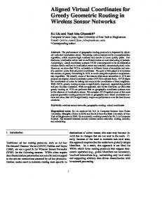
Figure 5. Fault-tolerance: the success ratio of GFR (k = 15, BRFM embedding generation) was tested for a varying failure rate. Also GFR with only a single embedding was evaluated. The shaded background represents the average success ratio, plus and minus the standard deviation σ.
Because of its breadth-first behaviour, no cycle avoidance or failed, the experiment is run 100 times and every time 1000 resolution is required, which greatly diminishes the complexity random source-destination pairs are generated between which of the embedding procedure. This results from the fact that a uniform traffic is simulated (as such 105 paths are simulated node can never increase its coordinate tuple length. The tree for each step). For each of these 1000 pairs the average success redundancy of the different generation modes in function of ratio is examined. To test link fault-tolerance, links�� are removed � � the number of trees generated k can be seen in Figure 4. For with a probability p(l) = exp 3 1 − dG (v)o , with v ∈ (dG (v)−1) RM, the values in Eq. (4) were set to η = 23 and β = 31 , which V the vertex that has the lowest p(l) probability of both vertices led to good behavior (no excessively deep trees in which lots incident to l ∈ E; dG (v)o the degree of vertex v before removal of cycles had to be resolved). From this it is clear that RM of any links. This probability makes sure that the link failures results in the lowest redundancy τ , BFM has the highest τ and are evenly spread across the network. When dG (v) = dG (v)o BFRM lies somewhere in between. In the next section we will (no incident links failed), the failure probability p(l) goes to show that a lower τ -ratio increases the fault-tolerance of GFR. one, while it goes to zero for dG (v) = 0 (nearly all incident links failed). Links are removed according to the description VII. R ESULTS AND DISCUSSION The routing behavior was simulated by a programmatic above randomly for each run of the experiment. Figure 5 depicts the routing success rate of GFR with k = 15 routing framework in which random source-destination host and routing with a single embedding, exercised on a scalepairs were generated continuously, corresponding to a uniform free graph with 500 nodes. GFR is able to attain a success traffic matrix. Between these pairs traffic was simulated by rate over 97% when 30% of the removable links are removed, generating routing paths in a multi-threaded environment. All given a connected network. This is a huge improvement over experiments were executed on a High Performance Computer. routing with a single embedding where the success ratio quickly The algorithms were tested on differently sized scale-free declines as the number of failures increases (success ratio less networks generated according to the Barab´asi-Albert model −γ than 50% at a 30% failure rate). This shows that GFR is [13] with a degree distribution of P (d) ∝ d with γ = 2.2. able to achieve high fault-tolerance without using any form of A. Fault-tolerance protection or restoration procedure, which is frequently used In this section the fault-tolerance of GFR will be evaluated. [4], [5], [6]. This inherent fault-tolerance can be explained by the availWhen using multiple embeddings, the chance of a network ability of more embeddings. Because of this, more alternate failure disrupting each of them becomes lower. Hence, the routing system is more likely to find a distance-decreasing pathways between source and destination exist. Therefore it is neighbour send on the packet. Therefore GFR should be more less likely that a routing void will occur, a situation in which resilient to failures than geometric tree-based routing using a no new �-decreasing neighbour can be found. From this can be concluded that GFR is fault-tolerant by its very nature (without single embedding. We only describe the effects of link failures in this section needing path restoration/protection), which is essential in a due to space constraints, however the node failure results are large-scale network where link or node failures are common. very similar. In the following experiment, the number of links Figure 6 shows how increasing the dimension k affects removed starts at 0 and goes up by 20 at each step. When GFR’s fault-tolerance at a link failure rate of 30%. In this representing the network by a graph G = (V, E), the highest experiment, for each k value, 15 different runs were executed number of links that can be removed without disconnecting G in which 105 random source-destination pairs were generated is (|E|−|V |+1). For every step in the number of links or nodes between which traffic was simulated. At low k-values, the
length of the shortest path between s and d.
100% 90%
500 nodes 2k nodes 8k nodes
1.30
70%
1.25
60%
1.20 ρ-
success ratio
1.35 80%
1.15
50%
avg ±σ avg
40% 1
5
10
15 k
20
25
1.10 30
1.05 1.00
Figure 6. Success rate at a link failure rate of 30% for a varying dimension k on a scale-free graph with 500 nodes. The embedding was generated according to BRFM. The shaded background represents the average success ratio, plus and minus the standard deviation σ. 100%
1
5
10
15 k
20
25
30
Figure 8. GFR with BFRM embedding generation: average stretch ρ¯ in function of the dimension k of the embedding space Tk for differently sized scale-free graphs.
In Figure 8 the effect of changing the number of embeddings k (or the dimension of the space Tk ) on the average stretch ρ¯ is depicted. For each k value, 15 different runs were executed 98% in which 105 random source-destination pairs were generated 97% between which traffic was simulated. The experiment shows asymptotic behaviour ρ¯ → 1 as k → +∞. This means that as 96% k increases, GFR starts to approximate shortest path routing. A RM BFRM logical explanation is that the availability of more embeddings BFM 95% allows for more routing freedom. As a result, there is an 0% 5% 10% 15% 20% 25% 30% increased chance that a combination of embeddings will lead link failure rate to a short path between two nodes. Therefore attaining a lower Figure 7. Effect of the different graph embedding procedures on the fault- stretch by increasing k goes hand in hand with higher faulttolerance of GFR (k = 15) on a scale-free graph with 500 nodes. tolerance. Based on these experiments we recommend using GFR with BFRM embedding generation due to its simplicity and its success ratio of GFR is low, which is consistent with Figure 5. relatively low tree redundancy. The dimension of the embedding As k increases, so does the success ratio, until it converges k should be chosen high enough to achieve a low stretch and towards 100% as k → +∞. This is consistent with more high fault-tolerance. However, how this parameter k can be embeddings allowing for more alternative paths by which estimated for unknown graphs remains future work. packets are naturally re-routed to their destination. The effect of the different graph embedding procedures on VIII. C ONCLUSION the success ratio is shown in Figure 7. It can be noticed that In this paper a theoretical framework was built which serves redundant mode (RM) is more robust to failures than breadthfirst mode (BFM) while breadth-first redundant mode (BFRM) as the foundation of a geometric routing scheme called Greedy lies somewhere in between. This indicates the correlation of Forest Routing (GFR). GFR performs greedy routing based on tree redundancy (see Definition 4) with fault-tolerance. The τ - a multi-dimensional embedding that has been constructed with ratios of the different embedding modes can be seen in Figure 4 minimal tree redundancy. It has been empirically shown to for varying values of k. This result is important as the gain in combine a low path stretch with robust fault-tolerance behavior, fault-tolerance does not require any alteration of the routing especially when compared to a single-dimensional embedding. procedure, it is entirely dependant on the initial embedding GFR enables natural traffic redirection without using any form of path protection or restoration mechanism. It is capable of procedure. guaranteeing success ratios as high as 97% at link failure rates B. Stretch of 30% in scale-free networks. The fault-tolerant behavior of GFR should not lead to Furthermore, due to the algorithm’s local routing decision excessively long routing paths. Therefore, in this section GFR making procedure no routing tables are needed, making it highly is analyzed regarding its average stretch ρ¯. We define the stretch scalable regarding memory requirements and robust towards of a generated path between a source node s and a destination network growth. Future work will encompass the addition of node d as the path length, in number of hops, divided by the load balancing characteristics to the routing decision engine and success ratio
99%
estimating an appropriate embedding dimension for unknown networks. ACKNOWLEDGMENT This work was carried out using the Stevin Supercomputer Infrastructure at Ghent University, funded by Ghent University, the Hercules Foundation and the Flemish Government – department EWI. This work is partly funded by the European Commission through the EULER project (grant 258307), part of the Future Internet Research and Experimentation (FIRE) objective of the Seventh Framework Programme (FP7). This project was partly funded by the UGent BOF/GOA project “Autonomic Networked Multimedia Systems”. R EFERENCES [1] B. Karp and H. T. Kung, “GPSR: greedy perimeter stateless routing for wireless networks,” in Proceedings of the 6th annual international conference on Mobile computing and networking, ser. MobiCom ’00. New York, NY, USA: ACM, 2000, pp. 243–254. [2] M. Bogu˜na´ , F. Papadopoulos, and D. Krioukov, “Sustaining the Internet with hyperbolic mapping,” Nature Communications, vol. 1, no. 62, Oct 2010. [3] D. Chen and P. Varshney, “A survey of void handling techniques for geographic routing in wireless networks,” Communications Surveys Tutorials, IEEE, vol. 9, no. 1, pp. 50–67, First 2007. [4] S. Sahhaf, W. Tavernier, D. Colle, M. Pickavet, and P. Demeester, “Link failure recovery technique for greedy routing in the hyperbolic plane,” Comput. Commun., vol. 36, no. 6, pp. 698–707, Mar. 2013. [5] ——, “Single failure resiliency in greedy routing,” in Design of Reliable Communication Networks (DRCN), 2013 9th International Conference, March 2013, pp. 306–313. [6] A. Cvetkovski and M. Crovella, “Hyperbolic embedding and routing for dynamic graphs,” in INFOCOM 2009, IEEE, 2009, pp. 1647–1655. [7] S. Ramasubramanian, H. Krishnamoorthy, and M. Krunz, “Disjoint multipath routing using colored trees,” Comput. Netw., vol. 51, no. 8, pp. 2163–2180, Jun. 2007. [8] M. M´edard, S. G. Finn, and R. A. Barry, “Redundant trees for preplanned recovery in arbitrary vertex-redundant or edge-redundant graphs,” IEEE/ACM Trans. Netw., vol. 7, no. 5, pp. 641–652, Oct. 1999. [9] G. Enyedi, G. Retvari, and A. Csaszar, “On finding maximally redundant trees in strictly linear time,” in Computers and Communications, 2009. ISCC 2009. IEEE Symposium on, July 2009, pp. 206–211. [10] M. Tang, H. Chen, G. Zhang, and J. Yang, “Tree cover based geographic routing with guaranteed delivery,” in Communications (ICC), 2010 IEEE International Conference on, 2010, pp. 1–5. [11] E. Ch´avez, N. Mitton, and H. Tejeda, “Routing in wireless networks with position trees,” in Ad-Hoc, Mobile, and Wireless Networks, ser. Lecture Notes in Computer Science. Springer Berlin Heidelberg, 2007, vol. 4686, pp. 32–45. [12] A. Korman, D. Peleg, and Y. Rodeh, “Labeling schemes for dynamic tree networks,” in STACS 2002, ser. Lecture Notes in Computer Science. Springer Berlin Heidelberg, 2002, vol. 2285, pp. 76–87. [13] A.-L. Barab´asi and R. Albert, “Emergence of scaling in random networks,” Science, vol. 286, no. 5439, pp. 509–512, 1999.
RNDM 2014 - 6th International Workshop on Reliable Networks Design and Modeling
Best paper award:
Program of RNDM'14 is available here.
Fault-tolerant Greedy Forest Routing for Complex Networks Rein Houthooft (BE), Sahel Sahhaf (BE), Wouter Tavernier (BE), Filip De Turck (BE), Didier Colle (BE), Mario Pickavet (BE) Region based Fault-tolerant Distributed File Storage System Design Under Budget Constraint Anisha Mazumder (US), Arun Das (US), Chenyang Zhou (US), Arunabha Sen (US)
Important dates Submission deadline: Notification deadline: Camera-ready: Registration:
Extended versions of top papers of analytic/optimization orientation will be considered for publication in a special issue of Networks journal (Wiley).
July 26, 2014 September 18, 2014 October 5, 2014 November 10, 2014
Patrons
RNDM has been established as a single-track workshop each time attracting world-class participants from both academia and industry working in the area of reliable networks design and modeling. RNDM 2014 follows the success of the first five events that took place in St. Petersburg (2009, 2012), Moscow (2010), Budapest (2011), and Almaty (2013) accordingly.
RNDM 2014 was organized by: Jacek Rak
Gangxiang (Steven)
James P.G. Sterbenz
(General Chair)
Shen (Co-Chair)
(Co-Chair)
2nd International Workshop on Understanding the inter-play between sustainability, resilience, and robustness in networks (USRR)
co-located with RNDM 2014 More information can be found here.
RNDM 2014 was technically co-sponsored by: - IEEE Spain Secion
file:///C|/Users/Administrator/Documents/dstevens/Publicaties%20INTEC/6238_i_i.htm[2/2/2015 10:28:26 AM]
RNDM 2014 - 6th International Workshop on Reliable Networks Design and Modeling - IEEE Communications Society (endorsed by TCCC) - IFIP TC6 WG 6.10 (Photonic Networking Group) - V.A. Trapeznikov - Russia (Northwest) Section BT/CE/COM Joint Chapter.
1st International Workshop on Survivable Content-Oriented and Cloud-Ready Networking
co-located with RNDM 2014 More information can be found here.
After a detailed review process, including at least 4 completed reviews per each submitted paper (on average: 4.27 completed reviews per each paper), accepted papers were were organized into seven technical sessions. Program of RNDM 2014 was enriched by two keynote talks, three invited presentations and a panel discussion. Similar to all previous editions, also this year all papers were presented (0% of noshows). Similar to previous years, we would like to thank the authors for their high-quality papers. Our sincere thanks also go to the Technical Program Committee, and external reviewers for their great effort in distribution of call for papers, as well as the timely delivery of detailed reviews. RNDM 2014 Chairs
file:///C|/Users/Administrator/Documents/dstevens/Publicaties%20INTEC/6238_i_i.htm[2/2/2015 10:28:26 AM]