able VT's is a crucial parameter for the decoder design and permits large savings in ... parallel nanowires storing the information or executing the com- putation at the ... This idea is founded on our underlying technology based on Gate-All-Around ...... www.cs.brown.edu/publications/theses/masters/2006/eerac.pdf, 2006.
Fault-Tolerant Multi-Level Logic Decoder for Nanoscale Crossbar Memory Arrays ∗
M. Haykel Ben Jamaa1 , Kirsten E. Moselund2 , David Atienza1,3 , Didier Bouvet2 , Adrian M. Ionescu2 , Yusuf Leblebici4 , and Giovanni De Micheli1 1
Integrated Systems Laboratory (LSI), EPFL, 1015 Lausanne, Switzerland. 2
Electronics Laboratory (LEG), EPFL, 1015 Lausanne, Switzerland. 3
4
DACYA, Complutense University (UCM), 28040 Madrid, Spain.
Microelectronic Systems Laboratory (LSM), EPFL, 1015 Lausanne, Switzerland. devices representing molecular switches with a large conductivity change depending on the molecular state, as well as thin nanowires, promising a very large integration density. The vanishing scale gap between these bottom-up techniques and the semiconductor industry suggests a hybrid approach consisting in integrating nanoscale wires and switches onto standard CMOS circuits by self assembly when the photolithography fails in achieving the targeted density. Both top-down and bottom-up approaches support a high device integration in a regular architecture called crossbars; these represent a simple circuits formed by two perpendicular strips of parallel nanowires storing the information or executing the computation at the matrix nodes (i.e. at the nanowires crosspoints) [2, 5]. The crossbar circuits can be realized as a separate part on the CMOS chip, where non-standard CMOS processing steps may be performed in order to achieve the sub-lithographic dimensions. Then, this part has to be connected to the outer CMOS part which is defined on the lithographic scale. One of the challenges is the design of the interface between the nano- and meso-scale parts. This is the decoder circuit, which allows the addressing of each single wire in the nanoscale part by the mesocale part. Previous approaches for designing the decoder range from a random attribution of the nanowire addresses [8, 20] to a deterministic mask-based decoder [1]. Unfortunately, the uncertainty of placement induces a large overhead in the decoder size, up to 5 times [15]. In this work, we will present a method to reduce the decoder size by implementing it in a multi-valued logic. This idea is founded on our underlying technology based on Gate-All-Around Silicon Nanowires (GAA SiNW) [25] which enables the fabrication of devices with multiple threshold voltages VT . Since VT shows a certain variability which increases when the device size shrinks, many defects are expected to happen; but the decoder robustness can be enhanced by optimizing the encoding and design parameters. This paper is organized in the following way. In the next section we review the work related to crossbar memories ranging from processes and devices to the memory architecture, and we focus on the decoder design. In Section 3, we present the decoder model and the underlying technology. Section 4 states the formalism and semantic used in multi-valued logic encoding. Then, we construct two kinds of encoding schemes (Section 5): the multi-valued hot and the n-ary reflexive codes. The defects affecting the decoders are defined and anlyzed in Section 6. We finally present the results of simulations performed on the decoder with both encoding schemes and under various reliability assumptions (Section 7), showing the area saving and highlighting the critical decoder parameters.
ABSTRACT Several technologies with sub-lithographic features are targeting the fabrication of crossbar memories in which the nanowire decoder is playing a major role. In this paper, we suggest a way to reduce the decoder size and keep it defect tolerant by using multiple threshold voltages (VT ), which is enabled by our underlying technology. We define two types of multi-valued decoders and model the defects they undergo due to the VT variation. Multi-valued hot decoders yield better area saving than n-ary reflexive codes (NRC), and under severe conditions, NRC enables a non-vanishing part of the code space to recover. There are many combinations of decoder type and number of VT ’s yielding equal effective memory capacities. The optimal choice saves area up to 24%. We also show that the precision of the addressing voltages for decoders with unreliable VT ’s is a crucial parameter for the decoder design and permits large savings in memory area.
1.
INTRODUCTION
At the end of roadmap for CMOS technologies, the top-down approach still provides many technological tools for continued downscaling. The device performance is improved by boosting the mobility while choosing different materials for the channel, straining it or rotating the substrate. Undesirable coupling effects between drain and channel can be suppressed by using Silicon on Insulator (SOI) or Silicon on Nothing (SON) devices. Advanced control of etching allows getting over the photolithographic limitations; several devices are based upon this gain, for instance Gate-All-Around Field Effect Transistors (GAA FET) [12], Double Gate FET [31] and Fin FET [10]. Since the top-down downscaling is becoming more challenging, many efforts were put in bottom-up approaches, which proved that another category of breakthroughs will permit additional scaling of circuits. The ability to design, fabricate and manipulate molecular-scale devices below the lithographic limits was recently demonstrated [4, 14, 27]. They include one- or two-dimensional ∗ This work is partially supported by the CCMX/MMNS project, the CSI Center, the FNS Research Grant 200021-109450/1 and the Spanish Government Research Grant TIN2005-5619.
Permission to make digital or hard copies of all or part of this work for personal or classroom use is granted without fee provided that copies are not made or distributed for profit or commercial advantage and that copies bear this notice and the full citation on the first page. To copy otherwise, to republish, to post on servers or to redistribute to lists, requires prior specific permission and/or a fee.
1-4244-1382-6/07/$25.00 ©2007 IEEE
2. RELATED WORK 2.1 Devices and Circuits Fabrication of silicon nanowires usually follows one of the two different approaches; bottom-up, where wires are grown, synthe-
765
sized or self-assembled onto the silicon substrate; and top-down, where nanowires (NWs) are fabricated from the substrate by more traditional means such as lithography, oxidation and etching. Both approaches present their unique advantages and disadvantages. Silicon nanowires with diameters of a few nanometer can be grown from gold nanocrystals dispersed on the silicon substrate [16], and electronic devices based on n- and p-type silicon nanowires have been fabricated by laser assisted catalytic growth [32]. The in-situ doping during the growth process, results in a radial [22] or axial [14] doping profile and makes it possible to differentiate NWs. The integration density which can be obtained with these wires can be very high; however, there is little or no control of the fluidic [30] placement of each wire, and thus contacting and interfacing to the rest of the circuit is difficult, and might reduce the benefits in terms of total circuit area. On the other hand nanowires obtained by stress-limited oxidation [18], by e-beam lithography [19] or by spacer technology [3] might not rival in integration density, even if the wire dimension is comparable to grown wires, the pitch is generally limited in one way or another by the technology. Recently, a novel top-down process called SNAP proved the ability of achieving a lithographyindependent pitch by using a superlattice as an imprint pattern [24]. Placement and contacting of NWs fabricated in a top-down process is generally not problematic, since the wires are defined by lithography, so the structures are aligned to the rest of the circuit. However, since they are identical, they necessitate a mask-based differentiation technique. In order to implement a controlled connection between the NWs, some sort of crosspoint is required. This could be implemented by a bistable NEMS switch as shown in [27] using suspended nanotubes having an energy barrier between the two switched states. In one of the states the nanotube is suspended above the crossing nanowire resulting in a very high resistance between the two conductors, and in the other state the two nanotubes are brought into contact, which leads to a low resistance current path. Recently, there has also been wide interest in the use of molecular crosspoints. In [29] a molecular monolayer sandwiched between two metal electrodes shows hysteretic switching as well as tunable resistance properties. In [23] the use of bistable molecular switches in a 2D crossbar structure is investigated. The concept of these switches is based on the molecular properties, which can be switched from a high resistance state to a low resistance state, and vice versa, by the application of an external voltage. Logic gates based on SiNWs and switching crosspoints were demonstrated in [17] and an architectural paradigm for building logic circuits was proposed in [5, 2], which relies upon a full logic out of NOR and OR planes. An architecture with cascaded sequences of OR/NOT planes is also proposed in [9, 6]. A different paradigm based on two-terminal components, NanoFabrics, is introduced in [13]. Besides interconnection and logic, SiNW crossbar arrays are highly suitable for information storage because of their regular structure and high density. The information is stored at the crosspoints in an ideally bi-stable molecular switch. A prototype for this kind of memory was reported in [23] and the writing, reading and erasing operations on information stored in molecular switches were demonstrated. Later on, it has been claimed that the integration of molecular switches may suffer from artifacts due to the binding between the switches and the wires [21]. In reference [3], the author improved the choice of materials and suggested a better design of the organic switch, claiming the elimination of the artifacts. The organization of the memory into smaller blocks and interfacing modules was presented in [7].
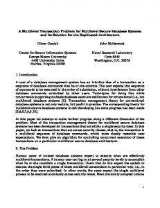
Figure 1: Decoder layout and circuit patterns (bottom-up), or deterministic mask-based patterns (topdown). Differentiated NWs have an axial or a radial doping profile which was defined during the NW growth process. An axial decoder was presented in [8]. In this decoder, the distribution of the VT ’s is fully random. The NWs are laid out parallel to each other. They are addressable when they have different VT patterns; this event has a certain probability that may be increased by increasing the number of addressing wires. On the other hand, the radial decoder [28] relies on NWs with several radial doping shells. After a series of etching of the NW shells, the remaining one in each region depends on the etching order. The suite of shells along the NW after all etching steps defines the NW patterns. Both axial and radial encoder give the same estimate of the number of mesowires (MWs) needed to address the available NWs; but the radial decoder is less sensitive to misalignment of NWs. In order to control undifferentiated NWs a mask-based decoder has been presented in [1]. The MWs are separated from the NWs by an oxide layer which is not uniform: at some locations a high-κ is used, in the others a low-κ dielectric. The high-κ dielectric amplifies the electric field generated by the MWs relatively to the low-κ dielectric. Only NWs lying under the high-κ dielectric can be fieldeffect controlled by the MWs. The oxide mask is lithographically defined; making the encoder depending on the lithography limits. There are other approaches for encoding undifferentiated NWs that are not mask-based. For instance, a random contact decoder has been presented in [20, 15], where the fully random connections between MWs and NWs through randomly deposited gold particles define the patterns of the NWs. Recently, an analog decoder called Micro to Nano Addressing Block, MNAB, was presented in [11]. It only needs two MWs, laid out parallel to the NW set. Depending on the pair of voltages applied at the MWs, the conduction in all NWs but one can be turned off.
3. CIRCUIT MODEL AND TECHNOLOGY The memory architecture considered in this paper is depicted in Fig. 2. It consists of two parts, organized in an identical way, and laid out perpendicularly to each other. Each part is a strip of N parallel nanowires divided into a set of bundles; the nanowires within each group have a common ohmic contact to a mesowire at either extremity of the bundle. Each group is defined lithographically. We assume that the circuit has a standard binary nanowire group decoder, which is not investigated in this paper since its design is well established on the lithographic scale. M mesowires are used to address the nanowires within each group. Then, the nanowire decoder of each group has the size N × M . The area sandwiched between the nanowire arrays is the actual memory, in which the information is stored in bi-stable switches grafted at the crosspoints. Each nanowire within a single group has to be addressed; this is performed by the nanowire decoder which is formed by a set of parallel mesowires crossing the nanowire array. The part of na-
2.2 Decoders The decoder is a circuit used in both logic and memories based on crossbar architecture. A schematic principle is shown in Fig. 1, where the aspect ratios are not precise. The use of two different VT ’s makes it possible, by applying suitable voltages at the vertical wires, to control which one of the horizontal wires will conduct; while the other horizontal wires will have a high resistance. The vertical wires are called control or addressing wires. Their number, thus the size of the decoder, depends on the encoding scheme and technology, which in turn follows from the fabrication approach: The encoding of NWs can be based on a random distribution of
766
Figure 3: A) Suspended silicon nanowire, substrate is covered by LTO. B) Focused ion beam (FIB) image of a cross-secion of the final device. C) Transmission electron microscopy (TEM) image of a device channel cross-section.
Figure 2: Crossbar memory architecture nowires under the decoder is coated by a dielectric, thus allowing a field-effect control of the nanowires by the mesowires of the decoder. The differentiation between the FETs can be technologically achieved in a general way by any of the means described in the previous section. The SiNWs fabricated to validate the proposed crossbar decoder architectures exploit the bulk silicon fabrication platform reported in [25]. The proposed access devices in the decoder are Gate-AllAround FETs. The nanowires are patterned into the doped Silicon substrate by a combination of isotropic etching and subsequent sacrificial oxidation. Whereupon a standard gate stack with 20 nm gate oxide is deposited, representing one of the decoder mesowires. Further details of the process can be found in [25]. The fabricated nanowires are parallel and have a length of several tens of micron, a cross-section circumference ranging from hundreds of nm to around 15 nm (smallest fabricated cross section diameter is 5nm), and a pitch depending on the lithography (optical or E-beam). Thus, in the proposed technology an increase in density, compared to CMOS, is not brought about by the lithographic scalability of the top-down process, but by using a unique crosspoint for both writing and storing information. A scanning electron microscopy image of a suspended silicon wire before the gate stack is implemented as shown in Fig. 3.A, and cross-sections of the device are shown in Fig. 3.B and 3.C respectively. This device may serve as an ideal component in an addressing decoder scheme, the gate length corresponds to the width of the poly-lines connecting to the meso-world, whereas the nanoscale channel can serve a dual purpose as both access device, and as one of the nanowires in a crossbar memory. The threshold voltage of the GAA FETs depends on the doping level of the channel, which is defined here by the substrate doping from which they are etched. Differentiation by doping is considered to reduce integration density, but since the top-down wires themselves are limited in pitch by the lithographic resolution in this technology, we do not consider this to be a major concern. In future ultra-scaled technologies, the differentiation might be possible by other means such as varying dielectric thickness. The second layer of parallel nanowires could be fabricated in a similar way, except the fact that it is patterned into polycrystalline Silicon deposited over the layer of nanowires, however this integration has not been demonstrated to date. It is preferable to use different doping levels from the same type to complementary doping types (n and p), because p- and n-regions need to be connected by a metal wire, which may actually increase the decoder size. So, we are experimenting with more than two doping levels; i.e. more than two VT ’s, and the decoder of the
memory will be based on a multi-valued logic. In the current technology, two different threshold voltages have been obtained by different bulk, and hence channel doping density. Multiple-VT should be possible as well. The technology using doping differentiated top-down nanowires, is considered as a possible future embodiment of such a decoding scheme, but by no means the only one. The idea of multi-valued logic decoder derives from its feasibility in our technology, but it is not inherent to it. The following sections investigate the types of multi-valued logic encodings that can be implemented, their impact on the decoder area and memory density, and the related reliability aspects.
4. MULTI-VALUED LOGIC ADDRESSING In this section, we generalize the notion of encoding to multiplevalued bits by first defining some basic relations needed to identify possible codes. The kinds of multiple-valued encodings that can be built are then presented in the next section. Some basic semantic used in encoding theory is generalized from the binary definitions stated in [26] to the multiple-valued logic used in this paper. The matching between a code and its pattern corresponds here to conduction, whereas in [26] it refers to a non-conducting state. Algebraic operations are performed as defined in the ring of integers. Definition 1. A multiple-valued pattern a, or simply a pattern a, is a suite of M digits ai , in the n-valued base B; i.e., a = (a0 , . . . , aM −1 ) ∈ BM , B = {0 . . . n − 1}. A pattern represents a serial connection of M GAA FETs in the SiNWs core; each digit ai of the code word represents a threshold voltage VT,i , with the convention ai < aj ⇔ VT,i < VT,j ∀i, j = 0 . . . M − 1. An analogue equivalence holds for ai = aj and consequently for ai > aj . Definition 2. A multiple-valued code word c, or simply a code word c, is, similarly to a pattern, a suite of M digits ci , in the nvalued base B = {0, . . . , n − 1}; i.e., c = (c0 , . . . , cM −1 ) ∈ BM . A code word represents the suite of applied voltages VA at the M mesowires. These are defined such that every VA,i is slightly higher than VT,i , and lower than VT,i+1 . Hence, a similar convention holds for the order of VA,i with respect to that of ci . Definition 3. A complement of digit xi in a code word or pattern x is defined as: NOT(xi ) = xi = (n − 1) − xi . The operator NOT
767
is obtained by a permutation of {cap0 , . . . , capP −1 }. Hence, there is at least one position pi for which holds capi > cbpi and at least one position pj for which holds capj < cbpj . This proves that �σ(cb − ca )� �= 0 and �σ(ca − cb )� �= 0 and that every two code words are independently covered. Then, Proposition 1 states that the whole code space is addressable.
can be generalized to the vector x, acting on each component as defined above. Notice that NOT(NOT(x)) = x. Definition 4. A pattern a is covered by a code word c if and only if the following relation holds: ∀i = 0 . . . M −1, ci ≥ ai . By using the sigmoid function (σ(x) = 0 ⇔ x ≤ 0, σ(x) = 1 elsewhere) generalized to vectors: σ(x) = (σ(x0 ), . . . , σ(xM −1 )), the definition above becomes: a is covered by c ⇔ �σ(a − c)� = 0. Alternatively, we can define the order relations on vectors c and a: c < a ⇔ ∀i, ci < ai and c > a ⇔ ∀i, ci > ai . The relation becomes an inequality if exists i such that ci = ai . Then, a pattern a is covered by a code word c if and only if a ≤ c.
P ROPOSITION 3. The size of the code space defined by a multivalued (k, M )-hot encoding is maximal for ki = M/n ∀ i = 0, . . . , (n − 1). The size of the maximal-sized space is asymptotically proportional to ∝ nM /M (n−1)/2 for a given n. Q P ROOF. The number of code words is given by M !/( ki !). This is a symmetric function of (k0 , . . . , kn−1 ). Maximizing this function for a real-valued vector k can be easily carried out by replacing ki ! by the Gamma function Γ(ki + 1), which gives the claimed statement. For a maximal-sized space, the Stirling formula yields for a large M : N = nM · (2π · M )1/2 /(2π · M/n)n/2 .
Under this assumption, the gate voltage applied at every GAA FETs is larger than its threshold voltages and turns it on. Therefore, the NWs having a pattern covered by the code word correponding to the applied voltages are conducting. Definition 5. A code word ca implies the code word cb if and only if �σ(cb − ca )� = 0. We note this as follows: ca ⇒ cb
In the rest of the paper, we implicitly mean the (k, M )-hot code with the maximal-sized space when we simply talk about the (k, M )-hot code.
This means that if a NW with the pattern corresponding to ca is covered by a code word c∗ , then the NW with the pattern corresponding to cb is also covered by the same code word c∗ . Applying the voltage suite c∗ will result in turning on the NWs with either pattern corresponding to ca or cb . a
5.2 N-ary Reflexive Code It is clear that an n-ary tree code is not addressable since some code words will imply some others. For instance, if n=3, then the code word 222 implies all other code words (000 . . . 221). It is possible to prevent the inclusive character of the n-ary tree code by attaching the complement of the code word (i.e., 222 becomes 222000). The as-constructed code is the N-ary Reflexive Code (NRC).
b
Definition 6. The code words c and c are independently covered if and only if ca does not imply cb and cb does not imply ca . This definition means that there exists a voltage suite that turns on the NW with the pattern corresponding to ca but not that with the pattern corresponding to cb ; and reciprocally, there exists a second voltage pattern that turns on the NW with the pattern corresponding to cb but not that with the pattern corresponding to ca .
P ROPOSITION 4. The code space defined by the NRC is addressable. P ROOF. The first (non-reflected) halves of any two code words ca and cb having the total length M (M is even) differ by at least one digit at say position i (i = 0 . . . (M/2−1)). Let ca be the code word such that cai < cbi . The reflection implies that caM −1−i > cbM −1−i . This proves that �σ(cb − ca )� �= 0 and �σ(ca − cb )� �= 0 and that ca and cb are independently covered. Then, Proposition 1 states that the whole code space is addressable.
Definition 7. The code word ca belonging to the set Ω is addressable if and only if it does not imply any other code in Ω\{ca }. We define the set Ω to be addressable if and only if every code word in Ω is addressable. If a NW has a pattern corresponding to an addressable code word, then there exists a voltage suite that activates only this NW and no other NW having its pattern in the set Ω.
In a similar way, the reflection principle works for any other code (e.g., Hamming code), making the whole code space addressable. However, in return it doubles the code length. Although the binary hot code is denser than the binary reflexive code, this statement holds for the multi-valued logic only if the codes are defect-free. This aspect is analyzed in the following sections.
P ROPOSITION 1. A set Ω of code words is addressable if and only if every code word in Ω is independently covered with respect to any other code word in Ω. P ROOF. This follows directly from Def. 6 and 7. Consequently, an admissible set of applied voltages that uniquely address each NW corresponds to the set of code words Ω that independently covers every pattern in A. This set of patterns can be simply taken as Ω itself, if Ω is addressable.
6. DEFECT MODELS The control of the SiNWs fabricated with our technology described in Section 3 is based on the modulation of the threshold voltage of the controlling GAA FETs. The encoding schemes proposed in Section 5 imposes a distribution of the applied control voltages between the successive threshold voltages (see Fig. 4). The main issue with the threshold voltage is its variability and process-dependency. If VT,i varies within a small range close to its mean value, then the pattern does not change, since the NW still conducts under the same conditions. Under certain conditions, the pattern undergoes defects and can be either i) not covered by any valid code word, in which case the NW cannot be discovered and the pattern is useless; or ii) covered by at least one valid code word. In the second case, if two patterns or more are covered by the same code word, then this code word cannot be used because more than one NW would have the same address. Thus, in the second case, the pattern is only useful if at least one code word covering it covers no other pattern, insuring that the covered pattern can be addressable. Assuming that in average every code word covers ν patterns when errors happen, let pI be the probability that a pattern remains
5. CODE CONSTRUCTION 5.1 Hot Encoding
Pk being an n-dimensional vector (k0 , . . . , kn−1 ), such that i ki = M , the multi-valued (k, M )-hot encoding is defined as the set of all code words having the length M such that each ki represents the occurence of the digit i, i = 0, . . . , n − 1. For instance, if k = (4, 3, 1), M = 8 and n = 3, then 00001112 and 00210110 belong to the considered (k, M )-hot code space. P ROPOSITION 2. The code space defined by a multi-valued (k, M )-hot encoding is addressable. P ROOF. Consider two code words ca and cb in code space defined by the (k, M )-hot encoding. Both codes are identical except at P different digits lying at the positions p0 , . . . , pP −1 . cb
768
described by the following vector d = (d0 , . . . , dn−1 ), where each di represents a pair of integers (dui , ddi ) expressing the number of flip-ups and flip-downs occurring in each digit group having the value i. Since no flip-down occurs at digits with value 0 and no flipup occurs at digits with value (n − 1), then we impose dd0 = 0 and du(n−1) = 0. Because the number of digits having the same value is by definition k, it must hold for every di : 0 � dui + ddi � k.Then, we distinguish two types of error bursts d:
υ: displacement of V
T,i
Probability density: f(V )
A,i
Flip−down
No defect
Flip−up
• Burst errors of type I: ∃i ∈ {0, . . . , i − 2}/dui > ddi+1 . • Burst errors of type II: ∀i = 0, . . . , (i − 2) : dui ≤ ddi+1 .
αV
0
εV
0
0
pd
V
T,i−1
Consider the case that a code word in Ω is transformed into a code word c∗ by a burst error d of type I. We denote by i the smallest position in d at which holds dui > ddi+1 . The number of digits in c∗ whose value is ≥ (i + 1) becomes larger than the permitted number in any code word cb in Ω, namely k · (n − i − 1). No code word would imply every digit of c∗ with a value ≥ (i + 1). Consequently, the NW with the pattern equal to the code word c∗ is not addressed by any permitted code word. The probability of defect type I is given by Algorithm 1.
δV
p
u
V
A,i−1
V
T,i
VA,i
V
T,i+1
Figure 4: Coding defects induced by VT variability Algorithm 1 pI = PA(xu , xd , i, p) 1: Construct D = all possible defects in subtree 2: for all y = (y u , y d ) ∈ D do 3: πsum ← 0 d u 4: p ← p · k!/(y d ! · y u !) · pyu · pyd 5: if i < n − 1 then 6: π ← (y d ≥ xu ) · PA(y u , y d , i + 1, p) 7: else 8: π ← (y d ≥ xu ) · p 9: end if 10: πsum ← πsum + π 11: end for 12: return πsum
covered, and pU the probability that a code word covers a unique pattern (pU = 1 − pU ). Let |Ω| be the original size of the code space and |Ω� | the size after errors happen. Then: |Ω� | = |Ω| · (1 − pI )(1 − pνU ) In order to assess |Ω� |, we first model single digit errors, and then burst errors. Thus, we analytically derive pI and pU , and ν is estimated as a fit parameter from Monte-Carlo simulations.
6.1 Single Digit Errors If the variability of VT,i is high or the spacing between two successive VT,i ’s is low due to the large number of doping levels, then VT,i may exceed VA,i − δ · V0 ; V0 being a given scaling voltage. While VT increases, the sensed current while ai is applied on the digit ci decreases (ai = ci ) and the sensed current while ai + 1 is applied on the same digit increases. We define a threshold VX,i = VA,i − δ · V0 where the sensed current for ai decreases by a factor q from its value at V T,i . Since the current in the saturation region of the GAA FET is proportional to (VA,i − VT )2 , where VT is the actual GAA FET threshold voltage, then the following condi2 2 tion on VX must hold: (V √ A,i − V T,i ) /(VA,i − VX,i ) = q; which gives: δ = (α + υ)/ q. When VT,i exceeds VX,i , the digit ai acts as ai + 1; its address becomes ci + 1 and we call this case the flip-up defect. Now, consider the case when VT,i falls below VA,i−1 − δ · V0 , then the current flowing while ai − 1 is applied is not ∼ 0 anymore, and always greater than q times the current flowing while ci − 2 is applied. Then, ai is implied by ci and ci − 1 but not by ci − 2; its address is ci − 1 which means that ai acts as ai − 1; this case is called the flip-down defect. When VT,i falls within the range between the threshold values for flip-up and flip-down defects, the digit is correctly interpreted. We notice that the flip-down error never happens at digits having the smallest value, 0, since the corresponding V T,i is by definition smaller than the smallest VA,i available. For the same reason, the flip-up error never happens at the digits having the biggest value, n − 1. In order to study the size of the addressable code space, we consider flip-up and -down errors in the code space instead of flip-up and -down defects at the nanowires, since both considerations are equivalent.
Now, let the code word ca in Ω be transformed into c∗ by a burst error d of type II. The number of digits in c∗ having the value i is always larger than the number of digits having the value (i+1). It is possible to construct one or more code words cb in Ω implying c∗ . An intuitive way consists in starting with the smallest digit value 0, and filling the digits of cb by 0 with respect to the positions hold by the value 0 in the digits of c∗ . The procedure is repeated iteratively on next digit values until all digits of cb are allocated (Algorithm 2). In Algorithm 2 we use the following notations: the number of digits having the value i in c∗ is li . Their respective positions are pi0 , . . . , pili −1 . The definition of the defect pattern d yields: li = k − dui + ddi+1 + dui−1 ∀i, with the convention dui−1 = 0 for i = 0 and ddi+1 = 0 for i = n − 1. Algorithm 2 Construct all cb 1: ν0 = k 2: for i = 0 to n − 1 do 3: Chose νi elements among S1 = {pii0 , . . . , pili } labeled S2 = {q0 , . . . , qνi −1 } 4: Allocate i to the digits of cb at positions S2 5: Allocate i + 1 to the digits of cb at positions S1 \ S2 6: νi+1 = k − li + νi 7: i← i+1 8: end for
6.2 Burst Errors in the k-Hot Code Space
Each choice of νi elements among li possible values gives many possible choices for cb . This proves that it is possible to find more than one single code word implying the incorrect code word c∗ . Now, consider the event that a code word covers a unique pattern when defects happen. All patterns that can undergo a burst error
Ω refers in the following to the code space of the maximal-sized multi-valued (k, M ) hot encoding in the base B = {0, . . . , n − 1} with k = (k, . . . , k) and M = k · n. We consider a code word c in Ω undergoing a series of single digit errors. The burst error is
769
• If cai undergoes a canceled flip-down error, then c0i is set to cai − 1.
and become covered by this code word are derived from it by a transformation T = (t0 , . . . , tn−1 ), where ti ∈ {0, . . . , k}n . tii+1 is the number of flip-ups at VT level i and tij (j < i) is the number of order-j flip-downs from VT level i to VT level j. Algorithm 3 determins all valid transformations, namely, those mapping a code space onto itself; S being the set of all (pi , µi ) representing respectively the probabilies of all possible transformations T and the number of their equivalent occurences. Then: pU =
X
µi · pi /(1 − pi ) ×
i=1,...,|S|
Y
• If cai undergoes a canceled flip-up error, then c0i is set to cai + 1. • If cai has no error, then c0i is set to cai . • c0M −1−i is set to n − 1 − c0i It is easy to verify that all patterns correponding to c0 constructed this way cover c∗ . In order to calculate the probability pI of the burst error type I, we can observe the complementary event (burst error type II or no error in code word ca ):
(1 − pi )µi
i=1,...,|S|
• If cai undegoes no error, then caM/2+i must undergo a flipdown or no error with the likelyhood: (1 − pu − pd )(1 − pu ).
Algorithm 3 S = PB(T, i) 1: Construct E = all possible transformations ti for VT level i 2: for all ti ∈ E do 3: Update T with ti 4: if i < n − 1 then 5: S ← S ∪ PB(T, i + 1) 6: else 7: if T is a valid transformation then 8: ui ← X tii+1 ∀ i 9: di ← tij ∀ i 10:
• If cai unergoes a flip-down error, then caM/2+i can have any value with the likelyhood: pd . • If cai undergoes a flip-up error, then caM/2+i must undergo a flip-down error with the likelyhood: pu pd . If we neglegt the adjustment due to the fact that no flip-down happens at i = 0 and no flip-up at i = n − 1, we get: pI = ((1 − pu − pd )(1 − pu ) + pd + pu pd )M/2
j