John S. Gero and José C. Damski ... email: {john,jose}@arch.usyd.edu.au .... Chapter. Gero and Park (1997), Chuang and Henderson (1990) and Gyankar and ...
Feature-Based Qualitative Modeling of Objects
John S. Gero and José C. Damski Key Centre of Design Computing and Cognition, Department of Architectural and Design Science, University of Sydney, NSW, 2006, Australia email: {john,jose}@arch.usyd.edu.au
Key words:
qualitative modeling, features, object modeling, computer-aided design
Abstract:
Objects represent fundamentally important ways with which to perceive and reason about the world. There are very few adequate representations for use at the early stages of designing. Feature-based approaches founded on qualitative representations have been used. This paper extends the qualitative representation developed for two-dimensional shapes to three-dimensional objects. It uses the qualitative representation to detect features. An example of the application of this representation is presented.
1.
MOTIVATION
This paper introduces and describes a qualitative approach to the modeling of objects applicable at the early stages of designing. It draws on and extends the work of Gero and Park on the feature-based qualitative modeling of two-dimensional shapes (Gero and Park, 1997). Objects are the fundamental building block of any building design system. Most modern CAD systems use objects. The problem with current approaches to the representation of objects in CAD systems in the need to be explicit about both object topology and object geometry. This is not a difficulty at the later stages of designing when these have been fixed but it is a problem at the early stages of designing. Qualitative approaches based on symbolic modeling provide the opportunity to represent objects as classes rather than as instances. As a consequence they can be 1
2
Chapter
used at the early stages of designing when objects do not yet have a fixed geometry, only an indicative one based on their topology. Further qualitative representations lend themselves to symbolic reasoning which can be used to convert the representation into one based on features. The use of features adds a dimension to the levels at which a system can reason about objects. Features lend themselves to semantic interpretations with labels which have meanings for human users. Thus, it becomes possible to carry out such reasoning as: for two objects to mate there must be a match between their protrusions and indentations, where protrusions and indentations are features. In this paper the qualitative approach to the modeling of objects applicable at the early stages of designing is extended through features to the feature-based qualitative modeling of objects. We use concepts derived from feature-based modeling to capture design knowledge related to the qualitative character of objects. This will be presented in three steps. The first step is to develop an appropriate representation scheme: this is based on previous work on syntactic pattern and contour representation methods (Gero and Park, 1997). The second step is to turn those qualitative descriptions of objects into a meaningful object semantics. The third step is to discover meaningful object, and then later design, semantics by using syntactic pattern matching of features from the given description of objects. Although the syntactic approach to the representation is not new, our syntactic representation scheme for qualitative characteristics of objects extends current generic methods and specialises them for design-related tasks which have previously either been unavailable or have been difficult. The term “qualitative” is the complementary word to “quantitative”. Qualitative methods normally handle variables within a symbolic system that is not necessarily based on a numeric scale, but based on comparisons and contrasts of relative magnitude and direction. Qualitative representations make only as many distinctions as necessary to distinguish objects and situations. They may be independent of any fixed scale of measurement and a single qualitative value can represent a range over a numeric interval. It represents an object with a set of qualitative symbol codes composed of a finite number of discrete symbols. A qualitative representation represents a class of objects rather than a single instance. In this sense it bears some connection to design prototypes (Gero, 1990). Setting qualitative values to object attributes follows a strict formalism suggested by researchers from the qualitative reasoning community (deKleer and Brown 1984). Qualitative values are set to variables by mapping their numeric values (where they exist) to a finite and discrete set of symbolic values. Where the numeric information does not exist, a lexigraphic ordering of the concepts can be used. The simplest way of setting qualitative values from the real number range of values is to use a “landmark set” with qualitative values in the range {- , 0, }. Then the set of intervals becomes {(- , 0), (0, 0), (0, )}, which corresponds to the qualitative set Q with the sign values {+, 0, -} (Wertner 1994). This simple yet effective process of symbolic mapping is useful in modeling design variables and attributes,
Feature-Based Qualitative Modeling of Objects
3
transforming possible numeric value ranges into small sets of discrete and finite symbol values. This formalism of setting qualitative values can be applied to most design variables since most values can be measured in terms of “polarity” and “granularity”. Whilst a number of object attributes may be used, here we demonstrate results obtained from using only one attribute, namely the angle between the bounding surfaces at their intersections. We take the standard graph theoretic representation of the boundary of solid objects and add angle semantics to the arcs to produce a semantic network representation as the qualitative representation of objects. From this qualitative representation we can reason about the mapping between unique structures in the semantic network and features.
2.
SYMBOLIC REPRESENTATION FOR OBJECTS USING Q-CODES
2.1
Basic formalism
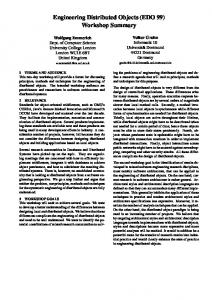
Researchers in the qualitative reasoning (de Kleer and Brown, 1984) have defined a set of qualitative values to a shape or object. This set of values is obtained by mapping (existent) geometric features into a set of discrete symbolic values. The commonest way to assign these symbolic values from numeric ones is to use a landmark set. The basic three attributes to represent a landmark of a shape or object are: • Angle represented by A and is the angle measured between two lines (or surfaces or tangents to surfaces in three-dimensional objects). It is measured from the line that lies in both surfaces. The intervals of values are {(0,0), (0,π), (π,π), (π,0)} which are mapped on to {Anil, A+, A0, A-}; • Length represented by L. It is the relative length of the line segment (or surface) compared to the previous one in a given order. The intervals of values are {(-∞,0), (0,0), (0,+∞)} which are mapped on to {L-,L0,L+}; • Curvature represented by K. It represents the relative curvature of the line segment (or surface) with values of "convex", "straight", and "concave" mapped on to {K+,K0,K-}. • The qualitative representation of an object is realized by encoding each face of the object following one or more of the above criteria. Figure 1 shows the Q-code encoding of some simple 2D faces. Those Q-codes are composed in similar way as in any natural language such as English. A sequence of Q-codes forms a word that may represent a shape pattern of significance such as a face of an object. A sentence, as a sequence of words, may describe an entire object. Such an analogy can be extended as we derive a semantic meaning from a sentence in similar way we can derive features from objects. Details of such representation and the reasoning process to obtain them can be found in
4
Chapter
Gero and Park (1997), Chuang and Henderson (1990) and Gyankar and Henderson (1990).
Rectangle 4*(A+)
Indentation 4*(A+)A+A-A+
Triangle 3*(A+)
Concave 3*(A+)
Protrusion 4*(A+)A-A+A-
Convex 3*(A+)
Figure 1. Q-code encodings of some simple faces, adapted from Gero and Park (1997)
The Q-codes representing the shapes in Figure 1 allow us to treat these shapes as exemplars of classes of shapes. Thus, the three shapes in the lower half of the figure are all, in some sense, triangles. All three have the same A-coding even though they appear to be different shapes. In two-dimensional shapes the landmarks occur at the vertices of the shapes. In three dimensional objects, as will be seen, the vertices are not the appropriate locus for landmarks.
3.
QUALITATIVE GRAPH REPRESENTATION OBJECT ANALYSIS
3.1
Semantic Net Graph model
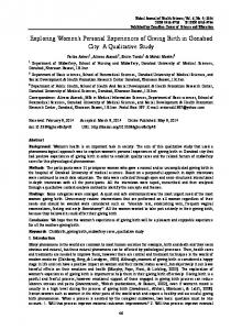
The geometry of three-dimensional objects can be represented as a set of vertices (points) and edges (lines) connecting the vertices. In this paper we represent an object as a set of faces and their relative position. This is implemented through a semantic net graph where each node represents a face (plan) and the arcs the connection between two faces (Mantyla, 1988). This connection is defined by a common line between planes. For each arc in graph model we assign a label "+" or "-" if the external angle measured between the planes are more (or equal) then 180° or less, respectively. Figure 2(b) illustrates this graph according for the L-shaped object shown in Figure 2(a). Figure 2(b) shows eight faces “a” to “h” and eighteen edges/arcs. As all angles between plans as more then 180°, all arcs are labelled as "+". We use this semantic net graph to represent the sequence of Q-code encodings of a 3D object and to extract qualitative information, such as features, by parsing this representation.
Feature-Based Qualitative Modeling of Objects
5 + + +
c +
e
+
b
+
g
a g h
h
f +
e +
+ +
d
+
+
+
a
+
d
f
+
b
c
+
(a)
+
(b)
Figure 2. (a) L-shaped object (b) semantic net representation
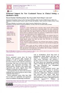
Some other examples of this semantic net graph representation of three-dimensional objects are shown in Figure 3.
g
+
j
b
+
+
e +
+ +
i
f
+
+
+
f
h
+ +
c
h
c d
b +
a
+
+
+
-
+
a +
-
+ +
e +
g
+
j
+
d +
i +
f
b
+
b i
h
h
d
j
+
+
+
g
d c
d -
e -
+
b +
+
c
h
e +
+
i +
i
-
+
+
f a
-
-
+
f
+
b
a
+
j
g
c ++
+
+
e a
+
i j
g
c
h
+ +
+ + +
+
+
+
f
+
+
+ +
d +
a +
-
+ +
e +
+
+ -
j
Figure 3. Objects and their semantic net graphs
+
g
6
Chapter
A vertex of a three-dimensional object is represented by a minimal circuit1 in the semantic net graph model. As the graph is non-directional, the orientation is not important. In this case a vertex is a sequence of labels "+" and "-" as we traverse a minimal circuit. Let us restrict ourselves to three-dimensional objects where only three planes intersect at each vertex. It is not difficult to generalise this restriction. In this situation there will be 4 types of vertices, labelled r, s, t and u: r +++
s ++-
t +--
u ---
Figure 4 shows the four possible types of intersections of three planes. They can be named outer corner (r), outer L shape (s), inner corner (t), and inner L shape (u).
u
t r
s
Figure 4. All possible combination of intersection of 3 planes
3.2
Vertex Graph
Given the semantics of vertices r, s, t and u it is possible to re-represent the semantic net as a vertex graph where nodes are the type of vertex and the arcs the connection between them. Using the example shown in Figure 2, the vertex graph is as shown in Figure 5. +
b
r +
g
-
s
e r
+
+ +
r
d
+
f
+
r
+
+
a +
r
+
+
+
c r
s
+
r
+
r
r
r +
h + Figure 5. Re-representing the semantic net as a vertex graph 1
Minimal circuit is a circuit which does not contain any other node.
Feature-Based Qualitative Modeling of Objects
7
The graph shown in dark lines in Figure 5 can be re-drawn as shown in Figure 6, which also labels the minimal circuits from a to f as the faces in the original object.
r
r c
r
s b
r
e
r
a s
r d
r
r h
r
f r
g Figure 6. Vertex graph model with faces labelled
In order to analyse the vertex graph model there are some semantic attributions necessary to interpret it. Table 1 shows some of these semantic attributions for objects with vertices composed of three planes intersecting. Table 1. Some semantic attribution to vertices with 3 planes intersection Feature Circuit Additional constraints Protrusion rrrr/tttt At least one r/t is adjacent to at least one s/u; or All r are connected to t; or All t are connected to r. Indentation ssss/uuuu All s/u are connected to r/t; or All s are connected to u; or All u are connected to s. Step rrss/ttuu L-Shape rrss/ttuu All r/t/s/u are adjacent to r U-shape ssss/uuuu ss/uu are connected to rr/tt the other ss/uu also connected to rr/tt Hole ssss Every s is connected to another s which make another circuit of s.
Using the interpretation shown in Table 1 and the graph in Figure 6 it is possible to detect the following features: • protrusion for faces c and d • L-shape for faces b and a. A more complete example is shown in Figure 7, where a prism sits inside a cavity. From the semantic net graph shown in Figure 7 it is possible to derive three separated graphs, as shown in Figure 8. The reason for three separated graphs is due to a lack of information about the connection between the vertices of the outside box to the vertices of internal hole. This is a classical problem in computer graphics where the basic solution is to create an artificial link to connect one structure to another. In our representation it is not necessary to create such an artificial link, because the semantic information about the planes are passed over from the representation of semantic net to vertex graph. This is one interesting feature of this re-representation.
8
Chapter
l o
p
m
k
n
g
j
-
h +
+
+
c
e
a
+
i
h
b
+
+
+
b
e
c
+
+
-
-
-
d
k
-
j g
+
+
-
-
-
+
+
+
d
i
+
+
f
o -
-
-
+
l
+
+ +
m +
+
p
+
n
f
a
Figure 7. A prism inside a cavity and its semantic net graph
a
+ +
-
h +
+
+
b
+
+
f
+ +
c +
d
+
+
e
+
+ +
o
i -
j -
-
-
-
k
-
g
+
+
l
-
-
-
+ +
m
-
+
+
+
p
+
n
Figure 8. Three separated graphs
Figure 9 show all three graphs and their faces.
r a r b r r c f e r r d r r
s g u h s u i e k s u j s u
t o r l t r k m p t r n t r
Figure 9. Detailed graphs with planes labelled
Analysing Figure 9 with Table 1 we can infer the following: • from the left graph: nothing can be inferred with the semantic feature set we currently have; • from the middle graph: there is an indentation formed between planes e and k; and • from the right graph: there is a protrusion formed between planes k and p.
Feature-Based Qualitative Modeling of Objects
9
It is possible to derive increasingly complex features by concatenating simple features. For example, knowing that an indentation is formed between planes e and k and that a protrusion is formed between planes k and p and that plane k is common to both features, it is possible to create a new feature: an annular indentation.
4.
ARCHITECTURAL EXAMPLE
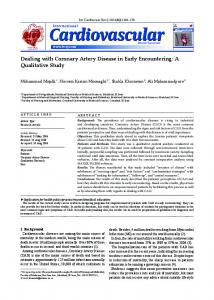
Figure 10 shows The Great Wall of China. A simplified model of the part of the Wall is shown in Figure 11, where the faces are labelled from a to r. A semantic net graph derived from the model in Figure 11 is shown in Figure 12. For simplicity of diagramming the thicker line represents the same label as the one at the end of the line.
Figure 10. The Great Wall of China
n
e
r b
f
p
j
g
c
h
d
i m
o
l k
a q Figure 11. A simplified geometric model of a section of The Great Wall of China
10
Chapter
+
+
+
+
+
b + c - d
+
p
+ + +
+
q
+
+
+
+
- e + f + g
+
+
+
+
+
r
- h - i +
+
+
j + k +
a
+
+ +
+
o +
+
+
n +
+
m + + l + Figure 12. The semantic net from Figure 11
Re-representing the semantic net shown in Figure 12 we obtain the vertex graph shown in Figure 13, with the faces now labelled within the vertices. q o
r r
r r
n r
r m
s
s
p
l
k
s
s
r
r b
r r
s c
r
d
s
r r
s
r
e
s
f
r
r a
s g
s h
s
r i
s
r j
r
r r
Figure 13. Graph re-representing the semantic net as a vertex graph
Applying the semantic attributes from Table 1 it is possible to detect the following features: • indentations in faces d, h, l; • protrusions in faces b, f, j, n • steps in faces c, e, g, i, m; and • U-shapes in faces m-l-r, c-d-e, g-h-i.
Feature-Based Qualitative Modeling of Objects
5.
11
DISCUSSION
Knowledge about shape and objects plays a major role in initial stages of design. Often it is the features in shapes and objects that are as significant as the shapes or objects themselves. Gero and Park (1997) developed a particular Q-Code representation for shapes as an associated reasoning process to detect features in shapes. In this paper we have presented a qualitative extension of that work to threedimensional objects. With this representation it is possible to reason about objects through their features unrelated to their specific geometries, since the object knowledge is derivable from the basic description of the object. From this basic description we build a semantic net graph representation. This semantic net is labelled with the relative position of each face of the object compared to its adjacent faces. The graph obtained from rerepresenting the semantic net shows the property of each vertex. It is interesting to note that the semantic information is carried on from one representation into another. We showed some basic features that can be obtained from the graph model. More complex features can inferred using a combination of those basic ones. For example, Table 1 shows a feature “hole” which is valid only if the two ends of the hole are directly connected. Figure 14 shows a more complex hole in the form of an L-shape.
Figure 14. L-shaped hole
Rules to detect such complex features can be built based on the same principles we used to build the basic features. These complex features may be developed targeting particular types of applications or a particular domains. What we have been able to show is that a qualitative representation of threedimensional objects provides the foundation for modeling and then detecting features. Feature-based modeling provides a fundamentally different means of describing objects than does geometry. Features may be concatenated to produce more complex features that can then be connected to domain knowledge so that other forms of analysis can be carried out. An obvious next question is whether it is possible to reverse the process and synthesise objects that exhibit desired features. This, however, is beyond the scope of this paper.
12
Chapter
ACKNOWLEDGMENTS This work is supported by a grant from the Australian Research Council, Grant No. A89802104. Computing resources are provided in part by the Key Centre of Design Computing and Cognition.
REFERENCES Chuang S and Henderson M R, 1990 Three-dimensional shape pattern recognition using vertex classification and the vertex-edge graph, Computer-Aided Design, 22(6): 377-387 de Kleer J and Brown J, 1984 A qualitative physics based on confluences, Artificial Intelligence, 24: 7-83 Gero J S, 1990 Design prototypes: a knowledge representation schema for design, AI Magazine, 11(4): 26-36. Gero J S and Park S-H, 1997 Computable feature-based qualitative modeling of shape and space, in R. Junge (ed.), CAADFutures 1997, Kluwer, Dordrecht pp. 821-830. Gayankar P and Henderson M R, 1990 Graph-based extraction of protrusions and depressions from boundary representations, ComputerAided Design, 22(7): 442-450 Mantyla M, 1988 An Introduction to Solid Modeling, Computer Science Press, Rockville Wertner, H. (1994) Qualitative Reasoning: Modeling and the Generation of Behavior, Springer-Verlag, Vienna.
This paper is a copy of: Gero, J. S. and Damski, J. (1999) Feature-based qualitative modeling of objects, in G. Augenbroe and C. Eastman (eds), Computers in Building, Kluwer, Boston, pp. 309-320.