Sep 17, 2010 - in Permanent-Magnet Synchronous Motors Using. Stator-Current Monitoring. Bashir Mahdi Ebrahimi and Jawad Faiz, Senior Member, IEEE.
IEEE TRANSACTIONS ON POWER ELECTRONICS, VOL. 25, NO. 10, OCTOBER 2010
2673
Feature Extraction for Short-Circuit Fault Detection in Permanent-Magnet Synchronous Motors Using Stator-Current Monitoring Bashir Mahdi Ebrahimi and Jawad Faiz, Senior Member, IEEE
Abstract—In this paper, a novel frequency pattern and competent criterion are introduced for short-circuit-fault recognition in permanent-magnet synchronous motors (PMSMs). The frequency pattern is extracted from the monitored stator current analytically and the amplitude of sideband components at these frequencies is introduced as a proper criterion to determine the number of shortcircuited turns. Impacts of the load variation on the proposed criterion are investigated in the faulty PMSM. In order to demonstrate the aptitude of the proposed criterion for precise short-circuit fault detection, the relation between the nominated criterion and the number of short-circuited turns is specified by the mutual information index. Therefore, a white Gaussian noise is added to the simulated stator current and robustness of the criterion is analyzed with respect to the noise variance. The occurrence and the number of short-circuited turns are predicted using support-vector machine as a classifier. The classification results indicate that the introduced criterion can detect the short-circuit fault incisively. Simulation results are verified by the experimental results. Index Terms—Classification, fault diagnosis, feature extraction, mutual information (MI), permanent-magnet synchronous motors (PMSM), short circuit, support-vector machine (SVM).
I. INTRODUCTION TATOR faults, which happen due to insulation failure, are categorized as turn-to-turn, coil-to-coil, phase-to-phase, and phase-to-ground fault. Early and accurate turn-to-turn fault diagnosis prevents occurrence of other aforementioned faults and ensures high reliability of permanent-magnet synchronous motors (PMSMs) as the costly motors. Since prediction of turnto-turn short circuit causes to rescue from the fault extension, it should be detected precisely. The inductances of the permanentmagnet brushless-dc (PMBLDC) motor under short-circuit fault have been calculated by finite-element method (FEM) in [1]. These inductances have been used in dynamic equations of the motor for performance analysis of the faulty PMBLDC motor. However, the convergence of these equations depends on chosen proper initial inputs of the FEM. The inset permanent-
S
Manuscript received November 1, 2009; revised March 17, 2010; accepted April 30, 2010. Date of current version September 17, 2010. Recommended for publication by Associate Editor A. M. Trzynadlowski. The authors are with the Center of Excellence in Applied Electromagnetics Systems, School of Electrical and Computer Engineering, College of Engineering, University of Tehran, Tehran 1439957131, Iran (e-mail: ebrahimibm@ ut.ac.ir). Color versions of one or more of the figures in this paper are available at http://ieeexplore.ieee.org. Digital Object Identifier 10.1109/TPEL.2010.2050496
magnet (IPM) and surface permanent-magnet (SPM) motors under short-circuit fault have been simulated by magnetic equivalent circuit (MEC) in [2]. It has been demonstrated that the peak of short-circuit current in the IPM motors is smaller than that of the SPM motors. The point is the MEC, without considering the B–H curve of the core materials, has considerable impacts on the results’ accuracy. Influence of the turn-to-turn fault on the stator currents and rotor speed has been studied in [3] in variable-reluctance PM motors. It has been illustrated that a major turn-to-turn fault is associated with a reduction in rotor velocity when the motor is driven with a brushless driver with closed-loop rotor-position feedback and open-loop voltage-speed control. It is noticeable that analysis of the motor signals’ amplitude is not a reliable approach for fault detection in electrical machines [4], [5], because load variation and supply condition can change motor-signal amplitudes. It has been revealed in [6] that the control strategies for PM motors under faults are different with that of the healthy case. The reason is noticeable effects of the fault on the measured torque and stator currents. Albeit efficient techniques have been used to control a faulty PM motor in [6], in which no method has been presented for fault recognition and only the fault-tolerant case has been analyzed. A PMBLDC motor under short-circuit fault has been modeled in [7] by FEM. It has been exhibited that appropriate protection against shorted turn faults is continuing to excite the affected phase with a suitable injected current at 90◦ lagging with respect to the phase electromotive force (EMF). Nonetheless, it has not been mentioned that how short-circuit fault can be predicted in the process of utilizing the aforementioned method to protect motor against fault. Indeed, protecting machines is impossible without proposing efficient indices for precise fault prediction. Stator currents, torque, and rotor speed of the PMBLDC motor under single-phase open circuit, turn-to-turn, and phase-to-phase short-circuit faults have been calculated in [8]. It has been shown that in the turn-to-turn short circuit, the current through the faulted coils increases significantly and could damage the coils. Furthermore, the terminal phase-tophase short circuit stops the running motor due to the zerotorque region, in terms of the rotor position. Although different signals of the faulty PMBLDC motor have been inspected in [8], no fault indicators have been demonstrated for fault identification. Intershort circuits of the stator windings of the PMBLDC motor have been diagnosed in [9] by analyzing the waveform of summation of the phase voltage and developed torque. It has been presented that the magnitude of the first-, third-, fifth-, and seventh-harmonic components can be used for intershort
0885-8993/$26.00 © 2010 IEEE
2674
circuits fault recognition. It is noticeable that the increase of harmonic components due to fault is not a proper criterion for fault detection in motors [10]. However, the main field generates harmonic components at aforementioned frequencies (i.e., first-, third-, fifth-, and seventh-harmonic components) due to the associated rotating force wave; also, the magnitude of these harmonic components is more dominant than the magnitude of aforementioned harmonic components due to the fault. The PM motor under short-circuit fault has been modeled in [11] by FEM and a three-level decomposition with db3 as the mother wavelet has been performed on the torque/current waveforms in order to derive fault signatures. The wavelet coefficients of the first frequency band (level 3, node 0) of the torque/currents have been selected as a criterion for fault diagnosis. Nevertheless, the nominated criterion has not been proved theoretically and experimentally, which is necessary to generalize and support the nominated criterion. An algorithm has been developed in [12] to identify intermittent electrical and mechanical faults in permanent magnet alternating current (PMAC) drives. This algorithm, which has been based on the prediction and classification of small transients in the stator currents corresponding to no catastrophic faults, can be used in conjunction with other factors to determine the remaining life of the drive. An analytical simulation technique according to the lumped-parameter model has been shown in [13] for short-circuit fault examination. Calculation of the model elements has been based on the extension of the winding function method. However, the nonlinear characteristics of the stator, rotor, and PM materials have not been taken into account and this leads to the unreliable simulation results. Moreover, no criterion has been presented for short-circuit fault detection in [13]. A mathematical model, that quantifies the variation of the slot-leakage flux as a function of the relative position of partially short-circuited turns, has been developed in [14]. It should be noted that performance analysis of the faulty motors in different conditions are the primary stages of the fault-detection procedure and proposing competent and applicable indices is the goal of this procedure that is missed in [14]. The second-level wavelet-packet-transform coefficients of line currents have been employed as inputs of a three-layer feed-forward neural network for short-circuit fault recognition [15]. It has been revealed that the illustrated method does not depend on the MEC model parameters of the PM motor. Albeit performance of the faulty PM motors has been analyzed in most of the papers [1]–[3], [6]–[11], [13], [14], a few criteria [12], [15] have been presented for short-circuit fault recognition in PM motors. Meanwhile, the later criteria [12], [15] have not been proved theoretically, which is necessary to generalize the proposed indices for any that kind of machine. This paper has four essential parts. In the first section, a threephase PMSM under 1, 2, 3, and 4 turn-to-turn short circuit fault is simulated by time stepping FEM (TSFEM) in order to calculate different signals of the motor for processing. In the second section, a novel frequency pattern is extracted theoretically from the stator-current monitoring based on the air-gap magnetic field scrutiny. Then, the amplitude of sideband components at these frequencies is introduced as a proper criterion for short-circuit fault diagnosis. In the third section, experimental results are
IEEE TRANSACTIONS ON POWER ELECTRONICS, VOL. 25, NO. 10, OCTOBER 2010
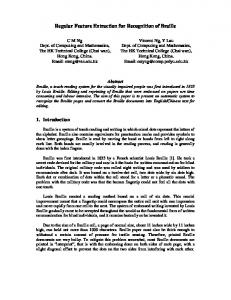
Fig. 1.
Cross section of modeled PMSM.
presented to verify theoretical analysis and TSFEM simulation results. In the fourth section, the discussed criterion is scrutinized from different aspects to evaluate the capability of the criterion for accurate fault detection. II. MODELING AND ANALYZING PMSM USING TSFEM FEM is used to determine magnetic field distribution within the motor, which is utilized to calculate current, torque, and speed of the motor. Fig. 1 presents a 2-D scheme of the simulated PMSM. The stator and rotor consist of laminated M-19 sheets and 36 slots in the stator filled with copper. The magnetization characteristics, magnetic orientation, and permeability (µr = 1.145) of the magnets (Nd-Fe-B) have been taken into account in the simulation procedure. Specifications of the proposed three-phase PMSM have been summarized in Table I. Transient analysis of rotating machines (RMs) from Opera-2 d FE software [16] is employed for modeling and analyzing the PMSM with mechanical coupling. The RM program is a transient eddy-current solver, extended to include the effects of rigid body (rotating) motion. Furthermore, it links external circuits to the FE region, which includes rotational parts. In the modeling of the PMSM under turn-to-turn short-circuit fault, three-phase sinusoidal voltages are applied to the motor terminals as inputs, magnetic flux density, and the stator currents are predicted as the selected signals for processing and feature extraction. In this simulation, electrical equations of the external circuits, which exhibit the supply and electrical circuits are combined with the magnetic field equation in FEM and motion equations due to the mechanical coupling. The 2-D propagation equation for magnetic field is as follows: ∂A Vs −σ + σν∇A (1) � ∂t where A is the z-component of the magnetic vector potential, v is the conductor speed with respect to the magnetic flux density, Vs is the applied voltage, and is the stack length in z-direction. The nonlinear equation, relating the FE equations and expressing the electromagnetic field of the machine with the circuit equations, is as follows [4]: � �T ∂A ∂∆V ∂i T = [Q] (2) [C] [A ∆V i] + [D] ∂t ∂t ∂t ∇ρ∇A = σ
EBRAHIMI AND FAIZ: FEATURE EXTRACTION FOR SHORT-CIRCUIT FAULT DETECTION IN PERMANENT-MAGNET SYNCHRONOUS MOTORS
2675
TABLE I SPECIFICATIONS OF THE PROPOSED THREE-PHASE PMSM
where i is the stator current, ∆V is the potential difference along the length of the conductor, [C] and [D] are the coefficients matrices, and [Q] is the vector related to the input voltage. Solution of (2) gives [i] as a necessary signal for processing. III. FEATURE EXTRACTION It is necessary to acquire most relevant features to detect fault using a reliable fault-prediction system. There are two strategies to obtain applicable features. The first method is related to the expert methods, which utilize autoregressive (AR) model, principal-component analysis (PCA), artificial neural network (ANN), and k-nearest neighbor (KNN) [5], [14]. In these approaches, features are coefficients of AR model extracted from the stator-current analysis. The PCA is applied to the features as a linear transform for dimension reduction and elimination of linear dependency of the features. In order to demonstrate the capability of these indices for fault estimation, KNN is employed as a classifier. In these methods, electrical machines are considered as a black box and outputs due for different inputs of the black box are analyzed for feature extraction. The second method is introducing an appropriate pattern based on the examination of the air-gap magnetic field. Hence, air-gap magnetic field components under short-circuit fault are determined and side effects of these components are assessed. It is noticeable that the fault-recognition procedures based on the magnetic field analysis are more reliable than the other schemes [17], [18], because in this method, physical characteristics of the healthy and faulty motors are taken into account for precise analysis in order to extract efficient patterns. A. Monitoring Air-Gap Magnetic Field Magnetic field contains full information about the stator, rotor, and mechanical parts of the motor. Therefore, continuous monitoring of the air-gap magnetic flux density can be employed to detect different faults in electrical machines [5], [11]. Hence, the air-gap permeance should be determined to analyze the air-gap flux density in the faulty motors. Moreover, impacts of the stator slots and saturation should be taken into account for precise flux-density calculation.
The air-gap length in the healthy PMSM, considering the influence of the saturation and stator slots, is as follows [19]: g (ϕ, t) = Rav − ρss cos (Sϕ) − ρsa cos (2ωr t − 2ϕ)
(3)
where Rav = Rs − Rr is the mean air gap, Rs is the stator inner radius, Rr is the rotor radius, ρss is the constant coefficient, S is the number of stator slots, ϕ is the space variable, ρsa is the constant coefficient, P is the number of pole pairs, ω r is the rotor rotational speed, and t is the time variable. The air-gap length is as follows: g (ϕ, t) = Rav (1 − δss cos (Sϕ) − δsa cos (2ωr t − 2ϕ)) (4) where δ ss = ρss /Rav and δ sa = ρsa /Rav . Since the air-gap permeance is the inverse of the air-gap length, the total permeance is approximated by � ∞ � −1 Λ(ϕ, t) = Rav 1 + δss cos Kss (Sϕ) K s s =0
+ δsa
∞ �
�
cos Ksa (2ωr t − 2ϕ) .
(5)
K s a =0
Since ω r = (1/P )ω s , (5) can be rewritten as follows: � ∞ � −1 cos Kss (Sϕ) Λ(ϕ, t) = Rav 1 + δss K s s =0
+ δsa
�
∞ �
cos Ksa
K s a =0
�� 2ωs t − 2ϕ . P
(6)
By applying Ampere’s circuital law, the stator air-gap field can be computed as follows [5]: � Bs (ϕ, t) = Λ(ϕ, t) µ0 js (ϕ, t) dϕ (7) where B is the magnetic flux density, µ0 is the permeability of free space, and js (ϕ,t) is the current density of the stator inner surface, which is expressed by js (φ, t) =
∞ � K c u =1
Js sin (Kcu ωs t − ϕ).
(8)
2676
IEEE TRANSACTIONS ON POWER ELECTRONICS, VOL. 25, NO. 10, OCTOBER 2010
Equation (8) can be utilized for nonsinusoidal voltage supply with different magnitude of the harmonic components in order to generalize the theoretical analysis. Combination of (6)–(8) represents the stator-flux density as follows: ∞ �
Bs (ϕ, t) = µ0
−1 Js cos(Kcu ωs t − ϕ)Rav
K c u =1
� ×
∞ �
1 + δss
cos Kss (Sϕ)
K s s =0 ∞ �
+ δsa
� cos Ksa
K s a =0
2ωs t − 2ϕ P
�� .
(9)
Fig. 2. Distribution of air-gap flux density in PMSM calculated by 2-D TSFEM.
Equation (9) can be simplified as follows: Bs (ϕ, t) =
∞ �
∞ �
∞ �
BK c u ,K s s ,K s a cos
K c u =1 K s s =0 K s a =0
×
� �� � 2Ksa Kcu ± ωs t − (1 ± 2Ksa ± Kss S)ϕ P (10)
where BK c u ,K s s ,K s a is the constant coefficient. In order to determine an expression for the rotor magnetomotive force (MMF) wave components, it is assumed that ϕ = ωt + ϕ� (ϕ� is the angle around the rotor circumference from a rotor reference point) and a similar scrutiny can be carried out for rotor air-gap field. Therefore, distribution of the magnetic flux density in the air-gap can be expressed as follows: B(ϕ, t) =
∞ �
∞ �
∞ �
K c u =1 K s s =0 K s a =0
��
×
Kcu ±
2Ksa P
BK c u ,K s s ,K s a cos �
� ωs t − λϕ
(11)
where Kcu , Ksa , and λ are constant coefficients. Equation (11) expresses the air-gap magnetic flux density in the healthy PMSM. Based on (11), stator current density, mean air gap, permeability, and coefficients (related to the influences of stator slots and saturation) affect the air-gap magnetic flux density. According to (11), a frequency pattern is proposed to extract sideband components in the magnetic flux density by � � 2Ksa (12) fField = Kcu ± fs P where fs = ω s /2π is the supply frequency. Based on (12), supply frequency, order of harmonic components of nonsinusoidal voltage supply, and saturation coefficient specify frequencies of magnetic flux density of the PMSM. When short circuit occurs, local saturation is established and, therefore, magnitude of the air-gap flux density increases. Meanwhile, distribution of the flux density is distorted, which is seen in Fig. 2. Analysis of these side effects, which are related to the saturation factor, can be utilized for feature extraction. Thus, amplitude of sideband components at frequencies (Kcu ± 2Ksa /P )fs is introduced as a proper criterion for short-circuit fault detection in PMSMs.
Fig. 3. Normalized magnetic flux density spectra of full-load PMSM in (top) healthy and 1 short-circuited turn and (bottom) 2 and 4 short-circuited turns.
It should be noted that saturation and harmonic components of voltage supply have considerable impacts on the frequency pattern, whereas amplitude of sideband components at frequencies (Kcu ± 2Ksa /P )fs is under influences of all saturation, stator slots, and voltage supply. However, due to the nature of the short-circuit fault, saturation impacts have the most vital roles for exact short-circuit detection in different fault levels. For the sinusoidal voltage supply, Kcu is 1 in (12) and, therefore, frequency pattern is presented as follows: � � 2Ksa (13) fField = 1 ± fs . P Fig. 3 demonstrates the power spectral density (PSD) of the magnetic flux density for the healthy and faulty PMSMs under 1 short-circuited turn. Fig. 3 illustrates that the amplitude of sideband components at frequencies (1 ± 2Ksa /P )fs increases
EBRAHIMI AND FAIZ: FEATURE EXTRACTION FOR SHORT-CIRCUIT FAULT DETECTION IN PERMANENT-MAGNET SYNCHRONOUS MOTORS
2677
considerably; this feature can be used as an efficient criterion for precise recognition of short-circuit fault. Fig. 3 reveals that the fault extension with 2 and 3 short-circuited turns raises the amplitude of sideband components at frequencies (1 ± 2Ksa /P )fs , which can be employed as a relevant criterion to determine the number of short-circuited turns. B. Stator-Current Monitoring Different techniques have been so far introduced for fault diagnosis; one of the major differences of these techniques is choosing a proper signal of the machine for processing. The selected signals could be electrical, mechanical, electromagnetic, and even temperature of the motor. Therefore, there is variety of fault diagnosis methods in electrical motors [8], [10]. Sensitivity of the chosen signal to the fault, the unique effect of the signal to any degree of the fault and accessibility of the appropriate sensors for the signal (quality and cost) are the criteria for choosing the most proper signal for the fault diagnosis. In order to have a noninvasive fault-diagnosis system, the stator currents that include the aforementioned criteria are chosen for monitoring and feature extracting. Since current flowing in the stator windings includes a series of space and time harmonics, spectrum analysis of the stator currents can be applied for feature extraction. Stator MMF is defined as follows: MMFs (ϕ, t) = g (ϕ, t) B (ϕ, t) .
(14)
Substituting (4) and (11) into (14) yields �� � � 2ωs t − 2ϕ MMF(ϕ, t) = Rav 1 − δss cos(Sϕ) − δsa cos P ×
∞ �
∞ �
∞ �
BK c u ,K s s ,K s a cos
K c u =1 K s s =0 K s a =0
��
×
Kcu
� � 2Ksa ± ωs t − λϕ . P
(15)
MMF (ϕ, t) =
∞ �
∞ �
IK c u ,K s s ,K s a cos
K c u =1 K s s =0 K s a =0
��
×
Kcu
2Ksa + 1 ± P
�
� ωs t − λϕ
at frequencies (1 ± (2Ksa + 1)/P )fs considerably that can be used as applicable criterion for short-circuit fault recognition. Meanwhile, referring to Fig. 4 indicates that the increase of short circuit turns to 2 and 3 causes the raise of the amplitude of sideband components at frequencies (1 ± (2Ksa + 1)/P )fs . This feature can be employed to predict the number of short-circuit turns. It is noticeable that the incremental rate of amplitude of sideband components at these frequencies is reduced due to the raise of number of short-circuited turns. IV. IMPACTS OF LOAD VARIATION ON NOMINATED CRITERIA
Equation (15) can be simplified as follows: ∞ �
Fig. 4. Normalized line-current spectra of full- load PMSM in (top) healthy and 1 short-circuited turn, and (bottom) 2 and 4 short-circuited turns.
(16)
where IK c u ,K s s ,K s a is the constant coefficient. According to (16), a frequency pattern extracted for short-circuit fault detection is introduced by � � 2Ksa + 1 (17) fCurrent = Kcu ± fs . P For the sinusoidal voltage supply (Kcu = 1), the frequency pattern is proposed as follows: � � 2Ksa + 1 (18) fCurrent = 1 ± fs . P Fig. 4 exhibits the spectrum of the stator current of healthy and faulty PMSMs under 1 short-circuited turn. It is seen that 1 turn short circuit raises the amplitude of sideband components
Considering control strategies, which are utilized to improve PMSMs performance [20], [21], thermal models, which can be coupled to electromagnetic models of PMSMs [22], and sensor faults, which have considerable impacts on the PMSMs performance [23], is necessary to propose comprehensive faultdetection methods. Accurate fault prediction is questionable without investigation of the relations between the criteria, load variation, and fault levels, even though taking all of the aforementioned conditions into account is difficult. Broken magnets, eccentricity, and misalignment faults in the PMSM with different load levels have been detected in [24]. It has been shown that the load variation has no noticeable influence on the faultdiagnosis index. Impacts of the load variation on the global indices have been inspected in [17] for eccentricity-fault recognition in induction motors. It has been demonstrated that the higher load reduces the magnitude of the discussed indices. Broken bar fault in the induction motor under different load levels has been predicted in [18]. It has illustrated that the broken bar increases the amplitude of the proposed index. Meanwhile, it has been emphasized that the accurate fault detection depends
2678
IEEE TRANSACTIONS ON POWER ELECTRONICS, VOL. 25, NO. 10, OCTOBER 2010
Fig. 5. Amplitude variation of sideband component versus number of short-circuited turns and load variation at frequency of [1–3/P ]fs , (a) magnetic flux density and (b) stator current.
on the comparison of the healthy and faulty induction motors at the same loads. The reason is related to the close correlation between the slip as a parameter, which expresses load variation and global indices in induction motors. Thus, side effects of the load variation on the nominated criteria should be determined. A. Magnetic Flux Density According to (12), the proposed frequency pattern, which can be presented as follows, is a function of harmonic components orders (Kcu ), number of poles (P ), saturation profile (Ksa ), and supply frequency (fs ): fField = g(Kcu , Ksa , P, fs ).
(19)
It is obvious that fs and P are constant and independent of the load variation. In addition, Kcu only depends on the harmonic components orders and, therefore, it does not change by load variation. Furthermore, effects of the load variation on the Ksa are ignorable for short-circuit fault. Since Kcu , Ksa , P , and fs are independent against load variation; fField does not change with the load variation. Variation of the PSD of sideband components at frequency (1–3/P )fs in the stator-current spectrum versus different load levels and short-circuit turns is revealed in Fig. 5(a). Since the speed of the PMSM is the synchronous speed, variation of load levels does not have noticeable impacts on the amplitude of sideband components at frequency (1–3/P )fs when the number of short-circuit turns is constant. According to Fig. 5(a), amplitude of the sideband components at frequency (1–3/P )fs rises due to the increases of the shortcircuit turns and it is fairly constant for load variation between no load and full load. Indeed, the proposed index is robust against the load variation and it is not necessary to specify the load levels of the motor for accurate fault recognition. Therefore, this index is much efficient than the global indices, which are utilized for fault diagnosis in induction motors. B. Stator Currents Fig. 5(b) exhibits the amplitude of the sideband components at frequency (1–3/P )fs for different number of short-circuit turns and load levels. Fig. 5(b) exposes that albeit the introduced criterion does not change perceptibly due to the load variations, it rises considerably due to short-circuit fault and increases of
Fig. 6.
Block diagram of a typical closed loop motor-drive system.
short-circuit turns.Comparison between Fig. 5(a) and (b) shows the same behavior from the proposed criterion against load variation point of view. V. EXPERIMENTAL RESULTS The experimental setup has been used to sample line currents, line voltages, and speed signal (by angular-speed sensor). The motor windings are ∆-connected and the third line current (Ic ) and line voltage (Vca ) can be easily estimated from the sampled currents and voltages, respectively. The block diagram of the PMSM drive has been shown in Fig. 6, which indicates the fault-detection system. This system is independent of the control system and only has the currents as inputs. The drive has an outer speed control loop, two inner current-controlled loops, and a pulsewidth-modulated (PWM) inverter feeding the PMSM [25]. An encoder is used to provide the rotor position for the transformation to the q-d-o-rotor rotating reference frame. For diagnosis purposes, it is assumed that only the stator voltage and current are measured. Stator currents and torque were sampled while the motor was in steady state and fast Fourier transforms (FFTs) were performed on the signals. A signalconditioning board, including voltage, current, and torque sensors, is designed and connected to the data acquisition system through voltage amplifiers to scale the magnitude and low-pass filters in order to obtain raw current, voltage, and torque data. A 12-bit A/D at 100 kHz PCI-1710HG FFT spectrum analyzer is used to monitor the real-time current and voltage spectra. Fig. 7 depicts the line-current spectra of the healthy and faulty PMSM with 1 turn shorted. Fig. 7 displays considerable increases of amplitude of sideband components at frequencies
EBRAHIMI AND FAIZ: FEATURE EXTRACTION FOR SHORT-CIRCUIT FAULT DETECTION IN PERMANENT-MAGNET SYNCHRONOUS MOTORS
Fig. 7.
2679
Normalized line-current spectra of full-load PMSM in (top) healthy and (bottom) 1 short-circuited turn-experimental results.
(1 ± (2Ksa + 1)/P )fs due to short-circuit fault. Comparison between Figs. 4 and 7 shows that amplitude of the sideband components at frequencies (1 ± (2Ksa + 1)/P )fs obtained in simulation results (see Fig. 4) is close to experimental results (see Fig. 7), which proves the theoretical analysis and simulated results.
TABLE II MI BETWEEN FEATURES AND SHORT-CIRCUIT FAULT
VI. ANALYSIS OF PROPOSED CRITERION To diagnose the short-circuit fault comprehensively, fault detection and determination of short-circuited turns are necessary. A proper criterion needs to have a high recognition rate along with a robust performance to environmental changes. The most important parameter in these tasks is the measurement noise. To evaluate the robustness of the proposed criterion, white Gaussian noise is added to the stator current and the variance of the noise is gradually increased until the recognition rate becomes unacceptable. It seems that the proposed criterion is capable to discriminate different number of short-circuited turns. To evaluate this ability and choose more applicable features, one of the widely used analyses in pattern recognition is performed on them. This analysis is based on the mutual information (MI) index, which is a common approach to measure nonlinear dependency. The MI of two variables is a calculation of common information or entropy shared between the two variables. The MI between each variable and the target can be defined as � � p (xi , y) dxdy (20) p (xi , y) log I(i) = p (xi ) p (y) xi y where p(xi ) and p(y) are the probability densities of xi and y, and p(xi ,y) is the joint probability density. The problem of calculating relationship between each criterion and number of short-circuited turns can be mapped into this framework. Assuming that xi is the criterion value and y is the number of short-circuited turns, the probability-density function of y can be computed easily, because in our experiment y has identical discrete value, i.e., n different values equals to the number of fault classes. Therefore, the main problem is to estimate p(xi ,y) and p(xi ). Here, the probability-density functions are approximated using Parzen method. Parzen method is one of the most famous nonparametric techniques for probability-densityfunction approximation due to its ease of implementation and good accuracy level. The kernel used for this estimation is a zeromean Gaussian with unit variance and the smoothing parameter
(bandwidth) is obtained by the least-square cross-validation algorithm described in [26], 0.00913 for estimating p(xi ) and 0.00839 for estimating p(xi ,y). In orderto solve problems, first the magnitudes of each feature have been normalized in such a way that they attain a value between –1 and 1 [see (21)]. Here, xi is value of the index and N is amount ofall data
xi,norm alized = 2
xi − mini xi − 1, maxi xi − mini xi
i = 1 : N. (21)
In Table II, the MI between the proposed criterion and the short-circuit fault in the presence of additive measurement noise is presented. The features which have higher relation with the number of short circuited turns while keeping this relation presence of noise are more appropriate than other features. It is clear that the proposed criterion is highly related to the number of short-circuited turns. As it can be seen, this criterion is sensitive to the noise and the MI decreases in presence of higher noises. Magnitude of (1–3/p)fs harmonic has highest relation to short circuit and keeps its relation in the presence of the high noise, even at S/N = 20 dB. Therefore, this feature may play a critical role in the short-circuit fault diagnosis. On the other hand, the magnitude of (1 + 1/p)fs has least relation to the short circuit and it is more sensitive to the noise than the others. Based on the high relation of the features to the number of short-circuited turns, it is expected that they can perfectly discriminate the number of short-circuited turns. Fig. 8 shows the scatter plot of the three features. It can be seen that the features can discriminate the number of short-circuited turns.
2680
IEEE TRANSACTIONS ON POWER ELECTRONICS, VOL. 25, NO. 10, OCTOBER 2010
TABLE III DETECTION OF SHORT CIRCUIT BY PROPOSED CRITERION
Fig. 8.
Scatter plot of three normalized features (S/N = 50 dB).
VII. ESTIMATION OF SHORT-CIRCUIT SEVERITY As the goal is to predict the number of short-circuited turns by these features, a hierarchical scheme is utilized for classification [27]. To estimate the short-circuit-fault severity, first, the fault is detected, and then the number of short-circuited turns is determined. Meanwhile, a KNN classifier is employed to identify the short-circuit fault and support-vector machines (SVMs) are used to specify the fault severity. A. Detection of Short-Circuit Fault KNN classifier is used for detection of the short-circuit fault. KNNs are nonparametric classifiers based on the nonparametric estimation of the class densities [28]. KNN classifiers find the k-nearest samples in some references set, by taking into account a majority vote among the classes of these k samples. It turns out that it is the estimation of the posterior probability by the proportions of the classes among the k samples. The aim is to find the nearest neighbors of an undefined test pattern within a hypersphere of predefined radius in order to determine its true class. Provided that the number of training samples is large enough, this simple rule exhibits noticeable performance. As this classifier is well known for two class problems in electrical machine fault detection (healthy and faulty machine) [29] with impressive results, here it is employed to estimate the short-circuit fault. The results of classification with various noise variances are presented in Table III, in which the proposed criterion can completely distinct healthy and faulty cases. As the noise level is increased, their ability is decreased; however, even at S/N = 20 dB, the correct classification rate is acceptable. The introduced criterion shows a robust performance in the presence of the noise for detection of short-circuit fault. B. Determination of Number of Short-Circuited Turns Albeit the main objective in fault-recognition systems is accurate fault detection, determination of fault severity is necessary to predict damage measure. Thus, the ability of this criterion must be evaluated by a classification system. The SVMs are utilized to estimate short-circuit severity. SVM is a relatively new and powerful technique for solving supervised classification problems and is very useful due to its generalization abil-
ity [30]. Its main idea is maximizing the margin between the training data and the decision boundary, which can be formed by hyperplanes. In other words, input points are mapped to a high-dimensional feature space, where a separating hyperplane can be found and then the algorithm is chosen in such a way as to maximize the distance between the decision boundary and the closest subset patterns, which are called support vectors. Given training vectors xi , i = 1, . . . , m in two classes, and a vector of labels di such that di ∈ {1, −1}, SVM solves a quadratic optimization problem � 1 ξi min (W T W ) + C w ,ξ 2 i=1 N
s.t. di ((W T Φ(xi )) + b) ≥ 1 − ξi ξi ≥ 0,
i = 1, . . . , N
(22)
where training data are mapped to a higher dimensional space by function Φ and C is a penalty parameter on the training error. For any testing instance x, the decision function is given by f (x) = sign(W T Φ(x) + b).
(23)
Practically, we need only K(x, xi ) = ΦT (x)Φ(xi ), the kernel function, to train the SVM. The radial-basis function kernel is used in our experiments � � �x − xi �2 . (24) K(x, xi ) = exp − 2σ 2 It is clear that the basic scheme of the SVM can only be used for the two classes of problems. For multiclass problem, the one-versus-all method is used. It assembles classifiers that distinguish one from all the other classes (for more details, see [30]). As the dataset consists of 100 current vectors for short-circuit values, 280 feature vectors are used as the training set (about 70% of total data) randomly and the other employed to test the classification performance. The reported results are acquired using 20 rounds of training—testing experiments. The results of classification are presented in Table IV, which include the average success on the training and test sets. The standard deviation, the best, and the worst performance of the classification results are also reported in Table IV. It is clear that the
EBRAHIMI AND FAIZ: FEATURE EXTRACTION FOR SHORT-CIRCUIT FAULT DETECTION IN PERMANENT-MAGNET SYNCHRONOUS MOTORS
2681
TABLE IV CLASSIFICATION RESULT OF USING INDICES TO DETERMINE NUMBER OF SHORT-CIRCUITED TURNS
indices are able to classify different types and degrees of eccentricities with low error rate in both test and training sets. Due to high capability for short-circuit fault classification, the proposed indices can be used to develop high-performance fault-detection systems. The degradation in performance is relatively high; as a result, the indices cannot be used at presence of high noise (e.g., S/N = 20 dB and less). VIII. CONCLUSION In this paper, a novel frequency pattern ((Kcu ± 2Ksa /P )fs ), which was extracted from magnetic flux-density spectrum was introduced for short-circuit fault diagnosis in PMSMs. Amplitude of sideband components at these frequencies was proposed as proper criterion for short-circuit fault detection. In this strategy, effects of saturation, stator slots, and nonsinusoidal voltage supply were considered. It was revealed that saturation and harmonic components of the voltage supply have considerable impacts on the frequency pattern, whereas amplitude of sideband components at frequencies (Kcu ± 2Ksa /P )fs is under influences of all saturation, stator slots, and voltage supply. In order to employ a noninvasive fault recognition method, a new criterion based on the stator-current monitoring was proposed. This criterion is the amplitude of sideband components at frequencies (1 ± (2Ksa + 1)/P )fs , which can be used for precise fault recognition. It was demonstrated that the presented index is robust against load variation, which can be used for short-circuit fault diagnosis in different loads. Meanwhile, the classification results, which were obtained from fuzzy support vector machine (FSVM) revealed that the exposed criterion can be utilized for short-circuit fault severity estimation in the presence of the high noise (S/N = 20 dB). As SVMs are one of the fastest highperformance classifier, this procedure for fault diagnosis can be performed in an acceptable time and, hence, makes the online diagnosis possible. REFERENCES [1] T. A. Nyamusa and N. A. Demerdash, “Transient analysis of partial armature short circuit in an electronically commutated permanent magnet motor system using an integrated nonlinear magnetic field-network model,” IEEE Trans. Energy Convers., vol. EC-2, no. 1, pp. 86–92, Mar. 1987. [2] T. Sebastian and G. Slemon, “Transient torque and short circuit capabilities of variable speed permanent magnet motors,” IEEE Trans. Magn., vol. MAG-23, no. 5, pp. 3619–3621, Sep. 1987.
[3] A. L. Nelson and M. Y. Chow, “Characterization of coil faults in an axial flux variable reluctance pm motor,” IEEE Trans. Energy Convers., vol. 17, no. 3, pp. 340–348, Sep. 2002. [4] B. M. Ebrahimi and J. Faiz, “Diagnosis and performance analysis of three-phase permanent magnet synchronous motors with static, dynamic and mixed eccentricity,” IET Electr. Power Appl., vol. 4, no. 1, pp. 53–66, Feb. 2010. [5] B. M. Ebrahimi, J. Faiz, and M. J. Roshtkhari, “Static, dynamic, and mixed eccentricity fault diagnosis in permanent magnet synchronous motors,” IEEE Trans. Ind. Electron., vol. 56, no. 11, pp. 4727–4739, Nov. 2009. [6] N. Bianchi, S. Bolognani, M. Zigliotto, and M. Zordan, “Innovative remedial strategies for inverter faults in IPM synchronous motor drives,” IEEE Trans. Energy Convers., vol. 18, no. 2, pp. 306–314, Jun. 2003. [7] A. J. Mitcham, G. Antonopoulos, and J. J. A. Cullen, “Implications of shorted turn faults in bar wound pm machines,” Inst. Electr. Eng., Proc. Electr. Power Appl., vol. 151, no. 6, pp. 651–657, Nov. 2004. [8] M. Dai, A. Keyhani, and T. Sebastian, “Fault analysis of a PM brushless DC motor using finite element method,” IEEE Trans. Energy Convers., vol. 20, no. 1, pp. 1–6, Mar. 2005. [9] M. A. Awadallah, M. M. Marcos, S. Gopalakrishnan, and T. W. Nehl, “A neuro-fuzzy approach to automatic diagnosis and location of stator inter-turn faults in CSI-fed pm brushless dc motors,” IEEE Trans. Energy Convers., vol. 20, no. 2, pp. 253–259, Jun. 2005. [10] D. G. Dorrell, W. T. Thomson, and S. Roach, “Analysis of air-gap flux, current and vibration signals as a function of the combination of static and dynamic air-gap eccentricity in 3-phase induction motors,” IEEE Trans. Ind. Appl., vol. 33, no. 1, pp. 24–34, Jan./Feb. 1997. [11] O. A. Mohammed, Z. Liu, S. Liu, and N. Y. Abed, “Internal short circuit fault diagnosis for pm machines using FE-based phase variable model and wavelets analysis,” IEEE Trans. Magn., vol. 43, no. 4, pp. 1729–1732, Apr. 2007. [12] W. G. Zanardelli, E. G. Strangas, and S. Aviyente, “Identification of intermittent electrical and mechanical faults in permanent-magnet ac drives based on time-frequency analysis,” IEEE Trans. Ind. Appl., vol. 43, no. 4, pp. 971–976, Jul./Aug. 2007. [13] Z. Sun, J. Wang, D. Howe, and G. Jewell, “Analytical prediction of the short-circuit current in fault-tolerant permanent-magnet machines,” IEEE Trans. Ind. Electron., vol. 55, no. 12, pp. 4210–4217, Dec. 2008. [14] R. Retana, A. Paweletz, and H. G. Herzog, “Analysis and detection of short circuit in fractional horsepower commentator machines,” IEEE Trans. Energy Convers., vol. 23, no. 2, pp. 484–491, Jun. 2008. [15] M. A. S. K. Khan and M. A. Rahman, “Development and implementation of a novel fault diagnostic and protection technique for IPM motor drives,” IEEE Trans. Ind. Electron., vol. 56, no. 1, pp. 85–92, Jan. 2009. [16] Opera-2D Reference Manual, Version 10.5, Vector Field Software Documentation, Oxford OX5 1JE, U.K., pp. 1–29, Ch. 5, 2005. [17] J. Faiz, B. M. Ebrahimi, B. Akin, and H. A. Toliyat, “Comprehensive eccentricity fault diagnosis in induction motors using finite element,” Trans. Magn., vol. 45, no. 3, pp. 1764–1771, Mar. 2009. [18] J. Faiz and B. M. Ebrahimi, “A new pattern for detection of broken rotor bars in induction motors during start-up,” Trans. Magn., vol. 44, no. 12, pp. 4673–4683, Dec. 2008. [19] B. Heller and V. Hamata, Harmonic Field Effects in Induction Machines. Amsterdam, The Netherlands: Elsevier, 1977. [20] J. Lee, J. Hong, K. Nam, R. Ortega, L. Praly, and A. Astolfi, “Sensor less control of surface-mount permanent-magnet synchronous motors based
2682
[21] [22] [23]
[24] [25]
[26] [27] [28] [29] [30]
IEEE TRANSACTIONS ON POWER ELECTRONICS, VOL. 25, NO. 10, OCTOBER 2010
on a nonlinear observer,” IEEE Trans. Power Electron., vol. 25, no. 2, pp. 290–297, Feb. 2010. V. Kinnares and C. Charumit, “Modulating functions of space vector PWM for three-leg VSI-fed unbalanced two-phase induction motors,” IEEE Trans. Power Electron., vol. 24, no. 4, pp. 1135–1139, Apr. 2009. G. D. Demetriades, H. Zelaya de la Parra, E. Andersson, and H. Olsson, “A real-time thermal model of a permanent-magnet synchronous motor,” IEEE Trans. Power Electron., vol. 25, no. 2, pp. 463–474, Feb. 2010. A. E. Ginart, P. W. Kalgren, M. J. Roemer, D. W. Brown, and M. Abbas, “Transistor diagnostic strategies and extended operation under one-transistor trigger suppression in inverter power drives,” IEEE Trans. Power Electron., vol. 25, no. 2, pp. 499–506, Feb. 2010. W. L. Roux, R. G. Harley, and T. G. Habetler, “Detection rotor faults in low power permanent magnet synchronous machines,” IEEE Trans. Power Electron., vol. 22, no. 1, pp. 322–328, Jan. 2007. B. M. Ebrahimi and J. Faiz, “Diagnosis and performance analysis of three-phase permanent magnet synchronous motors with static, dynamic and mixed eccentricity,” IET Electr. Power Appl., vol. 4, no. 1, pp. 53–66, Feb. 2010. M. C. Jones, J. S. Marron, and S. J. Sheather, “A brief survey of bandwidth selection for density estimation,” J. Amer. Stat. Assoc., vol. 91, no. 433, pp. 401–407, 1996. J. Yang, Low Noise Electrical Motors. London, U.K.: Oxford Univ. Press, 1981. R. O. Duda, P. E. Hart, and D. G. Stork, Pattern Classification, 2nd ed. New York: Wiley, 2002. I. Guyon and A. Elissee, “An introduction to variable and feature selection,” J. Mach. Learn. Res., vol. 3, pp. 1157–1182, 2003. N. Kwak and C. H. Choi, “Input feature selection by mutual information based on parzen window,” IEEE Trans. Pattern Anal. Mach. Intell., vol. 24, no. 12, pp. 1667–1671, Dec. 2002.
Bashir Mahdi Ebrahimi was born in Kermanshah, Iran, in 1979. He received the B.Sc. and M.Sc. (Hons.) degrees from the University of Tabriz, Tabriz, Iran, in 2004 and 2006, respectively. He is currently working toward the Ph.D. degree in electrical engineering from the University of Tehran, Tehran, Iran. During 2008, he was a Top Student Researcher at the University of Tehran. He is the author or coauthor of 33 papers in journals and 30 papers in international conference proceedings. His current research interests include design, modeling, control, and fault diagnosis of electrical machines and finite-element analysis of electromagnetic devices.
Jawad Faiz (M’90–SM’97) received the M.Sc. (Hons.) degree in electrical engineering from the University of Tabriz, Tabriz, Iran, in 1975, and the Ph.D. degree in electrical engineering from the University of Newcastle upon Tyne, Newcastle upon Tyne, U.K., in 1988. He is currently a Professor at the School of Electrical and Computer Engineering, University of Tehran, Tehran, Iran, where he is also the Director of the Center of Excellence on Applied Electromagnetic Systems. For ten years, he was a Faculty Member at the University of Tabriz. From 1988 to 1992, he was an Assistant Professor at the University of Tabriz, where he was an Associate Professor from 1992 to 1997. He is the author or coauthor of 135 papers in international journals and 148 papers in international conference proceedings. His current research interests include switched reluctance and voltage-regulator motors design, design and modeling of electrical machines and drives, transformer modeling, and the design and fault diagnosis in electrical machinery. Dr. Faiz is the Senior Member of IEEE Power Engineering, Industry Applications, Power Electronics, Industrial Electronics, Education, and Magnetics Societies. Since 1999, he has also been a member of the Iran Academy of Science. He is the recipient of a number of awards including the First Basic Research Award from the Kharazmi International Festival, in 2007, the Silver Einstein Medal for Academic Research from the United Nations Educational, Scientific and Cultural Organization (UNESCO), the First Rank Medal in Research as Eminent Researcher from the University of Tehran, in 2006, and the Distinguished Professor Award from the Iran Ministry of Science, Research and Technology, in 2004.