FET Noise Model Extraction Methods Jörgen Stenarson1,*, Niklas Wadefalk 1 , Mikael Garcia 2 , Iltcho Angelov1 , Herbert Zirath1 1
Chalmers University of Technology, Microwave Electronics Laboratory, 412 96 Göteborg, Sweden * E-mail:
[email protected] 2 Raytheon RF Components, CAD/modeling Dept., 362 Lowell Street, Andover, MA 01810, USA
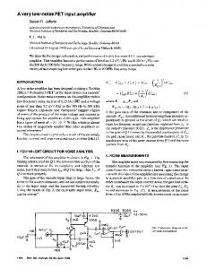
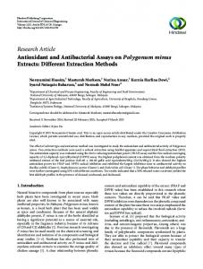
Abstract This paper presents an overview of the noise modeling extraction methods developed at the Microwave Electronics Laboratory at Chalmers University of Technology. The presented methods are suitable for different kinds of noise models, the one and two parameter Pospieszalski model, and the three parameter PRC model. We also present a low power low noise amplifier. Introduction To facilitate the development of high performance amplifiers, e.g. amplifiers for cryogenic temperatures with extremely low noise specifications it is important to have reliable and accurate models. There are two models commonly used for RF FETs (Field Effect Transistor); the Pospieszalski model [1] and the PRC model [2]. The Pospieszalski model use the temperature Td of the intrinsic drainsource resistance Rds , and also sometimes the temperature Tg of gate-source resistance Ri , Fig. 1a. The PRC model uses correlated noise current sources across the intrinsic gate-source port (i g with Tg =0), and intrinsic drain-source port (i d with Td =0), Fig. 1b. The next step is to extract values for the model parameters. There are several approaches available to do this extraction. The first approach is to use a physical model to calculate the model parameters. The second approach is to measure the noise figure, or noise parameters and use a circuit optimizer to get the model parameters. The third method is to measure the noise figure, or noise parameters and use some extraction algorithm to get the model parameters. The extraction algorithm approach is especially useful when implementing an automated extraction procedure. A bias dependent [3-5] model can be obtained by applying the extracted values from a range of biases and either generate a table-based model or a large-signal model with noise sources. This paper will focus on the extraction procedure but also mention our recent efforts in bias dependent modeling. Noise model extraction A general overview of the extraction process is shown in Fig. 2. As a first step cold FET S-parameter measurements are performed. These measurements are fed into the parasitics extraction algorithm [6]. This is done once for each device and the resulting circuit parameters are fed into an intrinsic circuit extraction routine for deembedding. The third step is to measure the device noise and S-parameters at all bias points of interest. The fourth step does the intrinsic extraction and the resulting equivalent circuit is fed into the noise extraction algorithm together with the noise measurements [4]. There are several choices of extraction algorithms depending on what kind of measurements are available [7-16]. This paper discusses three different methods useful for different kinds of measured data, summarized in Table 1. The direct methods presented here [13, 14, 16] use an admittance matrix description of the transistor. This approach makes it possible to use the same algorithms on other types of transistors than FETs. For the one and two parameter model, methods A and B of Table 1, we use (1) where F(Ys,j ) is the measured noise figure at source admittance Ys,j , j is the jth source impedance state, a i is calculated from the admittance matrix, and Ti is the temperature of each resistance in the equivalent circuit. The Ti can be either the model parameters or the other resistor temperatures held at ambient. For the one parameter model this gives us one equation, j=1, to solve for one measurement. For the two parameter model we need two measured noise figures, j=1,2, and we get a system of equations from (1).
F (Ys , j ) = 1 + ∑ ai (Ys , j )Ti
(1)
i
If we instead have measured noise parameters we could calculate the noise figure for some source admittance and use that with (1). There are however sensitivity problems with the choice of admittance
for the two-parameter model [14]. It is possible to calculate the Ys values that give a zero a i coefficient for any i this means we can choose the Ys,j that separates our system of equations to a system of two independent equations. Table 1 Direct extraction methods Measurement Extracted model One parameter model (Pospieszalski Td ) One noise figure (arbitrary Zs ) Two parameter model (Pospieszalski Td , Tg ) B Two noise figures (two arbitrary Zs ) C Noise parameters Two source model including correlation. (PRC, Pospieszalski) If noise parameters were measured they can be used directly in the extraction procedure [16]. This approach is suited for the extraction of models with two correlated sources, e.g. PRC. It is enough to use method B for models with no correlation, e.g. Pospieszalski, because it gives the exact same result as method C for the magnitude of the noise sources, this has not been proven mathematically but has been seen for all tried cases. A
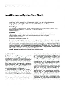
Discussion of extraction methods Several methods have been presented here. They are useful in different cases. For cryogenic applications where it is difficult to measure noise parameters some method that use few impedance states is preferable. Usually high performance transistors can be modeled by the Pospieszalski model. For this reason we prefer the first method above, Table 1, or using a circuit simulator to fit the one model parameter. We believe the first method is the most convenient one for a bias dependent model, it is however more complicated to implement especially if the device is measured in a fixture and not on wafer. The circuit simulator approach is more convenient for the model at a few bias points. It is possible to model the fixture and transistor and adjust the model parameter, Td , until simulation and measurement agrees. Another commonly used method is to measure the noise temperature of a complete amplifier. The advantage of this method is that the output of the amplifier can be matched, reducing errors due to source pulling of the receiver. The measured noise temperature is used with a circuit model of the complete amplifier to optimize measured noise vs. model. Bias dependent modeling A simple approach to bias dependent modeling is to extract the model for a number of bias points. The extracted parameters are put into a data file that can be interpolated by the circuit simulator. A dra wback with this method is that it requires a lot of measured noise data. The other way is to add a noise model to some large-signal model, in some circuit simulators there are suitable noise sources associated with the built-in large-signal models. The noise model parameters are functions of for instance the drain current, the parameters of this relationship are calculated from a few noise measurements. The advantage of this method is that it can cover a wider bias range with less measured noise data [4]. To extract the model parameters for each measured bias point the transistor's S-parameters were measured at 20K in a probe station. The equivalent circuit was extracted for each bias point using the hot/cold FET method [6]. The transistor was mounted in a special test fixture with a pre-matching circuit and gate bias-tee, Fig. 4. The pre-match circuit is used to get a narrow band Γopt match. The increased gain caused by the pre-match circuit helps reducing error contributions of following stages. The noise temperature was measured at 20K for several bias points, Fig. 3. Finally the noise models were extracted for each bias point by using a circuit simulator in order to model the pre-match structure and transistor. A two stage LNA has been used to verify the model. In order to simplify the design of low power LNAs the Chalmers model [4] has been extended to include noise sources. The noise source's bias dependence was modeled as a quadratic of Id , using the PRC configuration of the noise sources. The coefficients of the model were found by fitting to measured noise temperature at 8GHz for a range of bias points. Amplifier results A prototype 4-8 GHz low noise amplifier (LNA) designed for the FIRST (Far InfraRed and Submillimetre Telescope) satellite project has been designed. The goal is a high performance, Gain ~25dB and
Tn < 5K, amplifier working at a low power consumption Pdc25dB, Tn ~ 6K, and Pdc=22mW, while the InP version has Gain~25dB and Tn ~3K at 4 mW. Even when reducing the power consumption to 2mW, Vds =0.5V and Id =2mA, the noise temperature was degraded by less than 0.5K and the gain was only reduced by about 1dB. Conclusion In this paper we have presented an overview of extraction methods for noise models. These methods are useful in different circumstances. If a simple model is to be extracted at one bias point there is little need for a direct extraction procedure to be implemented and a circuit simulator might as well be used. But if more complicated and especially bias dependent models are to be extracted or if one wants to study the bias behavior of noise model parameters then an automated direct extraction method is more attractive. Acknowledgment The authors wish to acknowledge Swedish Space Corporation for the financial support of the FIRST project. The authors also acknowledge the valuable discussions and help from S. Weinreb, J. Fernandez from JPL and M. Pospieszalski from NRAO. References
[1]
[2]
[3] [4]
[5] [6] [7] [8] [9]
[10]
[11]
[12] [13]
M. W. Pospieszalski, “Modeling of noise parameters of MESFETs and MODFETs and their frequency and temperature dependence,” IEEE Transactions on Microwave Theory and Techniques, vol. 37, pp. 1340-50, 1989. R. A. Pucel, H. A. Haus, and H. Statz, “Signal and noise properties of GaAs microwave FET,” in Advances in Electronics & Electron Physics, vol. 38. New York: Academic Press, 1975, pp. 195-265. L. Klapproth, A. Schaefer, and G. Boeck, “A bias dependent HEMT noise model,” presented at IEEE MTT-S Int. Microwave Symp. Dig., 1997. I. Angelov, N. Wadefalk, J. Stenarson, E. Kollberg, P. Starski, and H. Zirath, “On the Performance of Low DC Power Consumption Cryogenic Amplifiers,” presented at IEEE MTT-S, 2000. R. A. Pucel, “A Proposed Model for the Temperature-Dependence of the Small-Signal Equivalent Circuit Parameters of the GaAs FET,” , 1987, Dec 26. M. Garcia, N. Rorsman, K. Yhland, H. Zirath, and I. Angelov, “Fast, automatic and accurate HFET small-signal characterization,” Microwave Journal, vol. 40, pp. 102-117, 1997. A. Riddle, “Extraction of FET model noise-parameters from measurement,” presented at IEEE MTT-S Symposium, 1991. M. T. Hickson, P. Gardner, and D. K. Paul, “HEMT models for s-parameter and noise parameter extrapolation,” presented at IEEE MTT-S Int. Microwave Symp. Dig., 1992. R. A. Pucel, W. Struble, R. Hallgren, and U. L. Rohde, “A general noise de-embedding procedure for packaged two-port linear active devices,” IEEE Transactions on Microwave Theory and Techniques, vol. 40, pp. 2013-2024, 1992. P. J. Tasker, W. Reinert, J. Braunstein, and M. Schlechtweg, “Direct extraction of all four transistor noise parameters from a single noise figure measurement,” presented at 22nd European Microwave Conf., 1992. P. J. Tasker, W. Reinert, B. Hughes, J. Braunstein, and M. Schlectweg, “Transistor noise parameter extraction using a 50 Ohm measurements system,” presented at IEEE MTT-S Symp osium, 1993. J. H. Han and K. Lee, “A new extraction method for noise sources and correlation coefficient in MESFET,” IEEE Trans. Microwave Theory Tech., vol. 44, pp. 487-490, 1996 Mar. M. Garcia, J. Stenarson, H. Zirath, and I. Angelov, “A Direct Extraction Formula for the FET Temperature Noise Model,” Microwave And Optical Technology Letters, vol. 16, pp. 208212, 1997.
[14]
M. Garcia, J. Stenarson, K. Yhland, H. Zirath, and I. Angelov, “A New Extraction Method for the Two-Parameter FET Temperature Noise model.,” IEEE Transactions on Microwave Theory and Techniques, vol. 46, pp. 1679-1685, 1998. P. Heymann, M. Rudolph, H. Prinzler, R. Doerner, L. Klapproth, and G. Bock, “Experimental evaluation of microwave field-effect-transistor noise models,” IEEE Transactions on Microwave Theory and Techniques, vol. 47, pp. 156-63, 1999. Stenarson, M. Garcia, I. Angelov, and H. Zirath, “A General Parameter Extraction Method For Transistor Noise Model,” IEEE Transactions on Microwave Theory and Techniques, vol. 47, pp. 2358-2363, 1999.
[15]
[16]
Drain
Gate + v -
Cgs Ri
Drain
Gate + v -
Cgs i=v g m R ds
Tg
ig
i=v g m R ds
Ri
id
Td
Source
Source
Fig. 1 Noise models for the FET, a) Pospieszalski and b) PRC respectively.
S-parameter Measurement
Small-Signal Circuit Extraction (Parasitics)
S-parameters ColdFet
Small-Signal Circuit Extraction (Intrinsic)
Noise Measurement
Noise Model Extraction
Fig. 2 Example of extraction procedure. 50
Vd=0.4 Vd=0.8 Vd=1 Vd=2
Noise(T)
40
30
20
10
0 2
3
4
5
6
7
8
Frequency (GHz)
Fig. 3 Noise Temperature. Vd as parameter. Id =5mA. Noise (K) measured
Gain (dB) simulated
Noise (K) simulated
Vd1=Vd2=0.7V Id1=Id2=2.8mA
4-8GHz LNA#6E2 at 15K with MGFC4419G 30
25
25
20
20
15
15
10
10
5
0 3
4
5
6 Frequency (GHz)
7
8
9
Gain (dB) measured
Noise (K) simulated
Gain (K) simulated
Noise (K) measured
4-8GHz LNA#6G1 at 15K With InP28_QED 30
30
25
25
20
20
15
15
10
10
5
5
5
0
0
Noise (K) measured
30
Td=400K Tg=15K
Noise (K)
Gain (dB)
Td=1050K Tg=15K
Gain (dB) measured
Gain (dB) measured
Vd1=Vd2=2.20V Id1=Id2=5.0mA
Fig. 4 Noise measurement pre-match circuit.
0 3
4
5
6
7
8
9
Frequency (GHz)
Fig. 5 Measuredand simulated results of LNA with GaAs (MGF4419G) and InP (Chalmers) transistor.