RADIOENGINEERING, VOL. 19, NO. 3, SEPTEMBER 2010
455
FGMOS Based Voltage-Controlled Grounded Resistor Rishikesh PANDEY1, Maneesha GUPTA2 1
Dept. of Electronics and Communication Engineering, Thapar University, Patiala, Punjab-147004, India Dept. of Electronics and Communication Engineering, Netaji Subhas Institute of Technology, New Delhi-110078, India
2
[email protected],
[email protected] Abstract. This paper proposes a new floating gate MOSFET (FGMOS) based voltage-controlled grounded resistor. In the proposed circuit FGMOS operating in the ohmic region is linearized by another conventional MOSFET operating in the saturation region. The major advantages of FGMOS based voltage-controlled grounded resistor (FGVCGR) are simplicity, low total harmonic distortion (THD), and low power consumption. A simple application of this FGVCGR as a tunable high-pass filter is also suggested. The proposed circuits operate at the supply voltages of 0.75 V. The circuits are designed and simulated using SPICE in 0.25-m CMOS technology. The simulation results of FGVCGR demonstrate a THD of 0.28% for the input signal 0.32 Vpp at 45 kHz, and a maximum power consumption of 254 µW.
high-pass filter operating at supply voltage of ±0.75 V. The operations of the proposed circuits have been simulated using SPICE in 0.25-m CMOS technology.
2. Operation of FGMOS A cross section of a typical n-channel, N-input FGMOS is shown in Fig. 1. The FGMOS differs from a conventional MOSFET in that it has one more gate called the floating gate, which is completely isolated within the oxide. Floating Gate V 1 Source
C1
N-input voltages V2
V3
VN CN
C3
C2
Input Gates Drain
Keywords Floating gate MOSFETs, low-voltage, voltagecontrolled grounded resistor, SPICE.
N+
N+
p-substrate
1. Introduction Lowering power supply voltage is the most efficient method to reduce power dissipation and raise system reliability. Some of the low voltage techniques used to reduce supply voltages are level shifters, self-cascode MOSFETs, sub-threshold MOSFETs, bulk-driven MOSFETs, and floating gate MOSFETs (FGMOS) [1], [2]. Out of these FGMOS presents a unique advantage of programmability of threshold voltage, which can be lowered from its conventional value, thus makes it suitable for low voltage applications [3], [4]. FGMOS is compatible with standard double-poly CMOS process technology and has been used to develop digital-to-analog (D/A) and analog-to-digital (A/D) converters [5], resistors [6]-[9], electronic programming [10], neural networks [11], and operational transconductance amplifier [12], etc. Motivated by the unique characteristics of the FGMOS, a FGVCGR is presented in this paper. The voltage-controlled resistors find applications in the area of analog signal processing such as filters [13-15], oscillators [16], [17], and amplifiers [18], etc. The paper presents FGVCGR and its simple application as tunable
Fig. 1. Structure of an N-input FGMOS.
The voltage on the floating gate VFG of Fig. 1 is expressed as [19]: N
VFG
C V C i 1
i i
fd
VDS C fsVSS C fbVBS QFG CT
(1)
and the total capacitance CT of the floating-gate is N
CT Ci C fd C fs C fb
(2)
i 1
where C1, C2, C3, ….. , CN are the input capacitances N between control gate and floating gate, Ci is the sum of i 1
N-input capacitances, Cfd is the overlap capacitance between floating-gate and drain, Cfs is the overlap capacitance between floating-gate and source, Cfb is the parasitic capacitance between floating gate and substrate, Vi is the input voltage at the ith input gate, VDS is the drainto-source voltage, VSS is the source voltage, VBS is the
456
R. PANDEY, M. GUPTA, FGMOS BASED VOLTAGE-CONTROLLED GROUNDED RESISTOR
substrate-to-source voltage, CT is the total capacitance of the floating-gate and QFG is the residual charge which can be neglected during the fabrication process using the method suggested in [20]. Therefore equation (1) reduces to: N
VFG
C V C i i
i 1
fd
VDS C fsVSS C fbVBS
(3)
.
CT
VIN IIN
Vb VC
(IIN – I1)
I2
I1 M1
M2
N
If
C
i
i 1
>> Cfd, Cfs, Cfb, then equations (2) and (3) are N
modified as CT =
C , and VFG = C Vi/CT i 1
i
i 1
.
i
Fig. 3. Voltage- controlled grounded resistor.
The drain current equations for the n-channel FGMOS have been obtained by modifying the conventional n-channel MOSFET equations. The drain currents IoDS and ISDS in the ohmic and saturation region respectively, are:
o I DS
N CiVi V V V 1 V 2 , (4) K n i 1 SS T DS DS 2 CT
S I DS
N CiVi K V V n i 1 SS T 2 CT
2
(5)
where Kn =μn Cox (W/L) is the transconductance parameter, μn is the electron mobility, Cox is the gate-oxide capacitance per unit area, (W/L) is the aspect ratio of the transistor, and VT is the threshold voltage of FGMOS. The symbol and equivalent circuit model for an N-input FGMOS are shown in Figs. 2(a) and (b) respectively, where Vi (for i = 1, 2, …, N) are the control inputs and D, S and B are the drain, source and substrate, respectively.
N-input voltages
V1 V2 V3 VN
D
C1 C2 C3
V1
B
CN
V2 V3
S Input gates
D
VN
Cfd
C1
B
VFG
CN
The drain current I2 is given as:
I2
Kn2 VIN VSS VTn 2 2 2
(7)
where VIN in the input voltage, Kn1 and Kn2 are the transconductance parameters, VTn1 and VTn2 are the threshold voltages of the transistors M1 and M2 and k11 = C1/CT, k12 = C2/CT are the capacitive coupling ratios of the transistor M1. From Fig. 3, it can be seen that the input current of the circuit is the sum of both drain currents I1 and I2, i.e.
I IN I1 I 2 .
(8)
By choosing Kn1 = Kn2 in (8), the squared terms of input voltage VIN is cancelled out, (since k11 + k12 = 1) and we get:
I IN K n1VIN k11Vb k12VC VTn1 VSS VTn 2 I offset (9)
Requ VIN / I IN
K n1 k11Vb k12VC VTn1 VSS VTn 2 1
Cfs Cfb
(a)
V2 I1 K n1 k11 Vb VSS k12 VC VSS VTn1 VIN IN .(6) 2
Hence, the simulated resistance from (9) is
C2 C3
In Fig. 3 the transistors M1 and M2 are connected in parallel where M1 and M2 are operating in the ohmic and saturation region respectively. Using (4), we can express the drain currents I1 as:
where Ioffset = (VSS + VTn2)2. From (9), it is observed that a linear relationship can be obtained if Ioffset is eliminated from the equation. Fig. 4 shows the proposed FGVCGR in which the offset component is eliminated by adding another transistor M3 (perfectly matched with M2 i.e. Kn2 = Kn3, VTn2 = VTn3) and a simple current mirror formed by the transistors M4 and M5 to the circuit shown in Fig.3.
3. Proposed Voltage-Controlled Grounded Resistor Floating gate
VSS
N
S
(b)
Fig. 2. FGMOS: (a) Symbol. (b) Equivalent circuit model.
(10)
From (10), it can be seen that the proposed circuit behaves as voltage-controlled grounded resistor and the value of the equivalent resistance Requ is tuned by control voltage VC. The input voltage range for the transistor M1 to
RADIOENGINEERING, VOL. 19, NO. 3, SEPTEMBER 2010
457
operate in the ohmic region may be derived as 0 ≤ VIN < (k11Vb + k12VC - VTn1). VDD
with those of the voltage-controlled grounded resistor reported in [13] and [15]. The total power dissipation of the proposed FGVCGR is 0.254 mW. Fig. 7 shows the frequency response of the proposed tunable high-pass filter.
Vb1 M5
M4
150uA
VIN IIN
Vb VC
(IIN – I1) I1
M1
100uA
Ioffset Ioffset
I2 M2
M3
50uA
0A
VSS
Fig. 4. Proposed voltage-controlled (FGVCGR).
0V IIN
40mV
80mV
120mV
160mV
200mV 240mV
280mV 320mV
VIN
Fig. 6. I-V characteristics of the proposed FGVCGR.
grounded
resistor
0 -20
4. Proposed Tunable High-Pass Filter The proposed FGVCGR can be used in communication systems and analog signal processing applications. However in this paper we have used it for the realization of tunable high-pass filter shown in Fig. 5.
C= 10pF Vin=0.12V
Vout Proposed FGVCGR
Fig. 5. Proposed tunable high-pass filter.
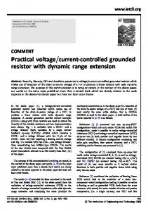
5. Simulation Results All the proposed circuits have been simulated using SPICE in 0.25-m CMOS technology. The SPICE model parameters and the aspect ratios are listed in Tab. 1 and 2 respectively. Fig. 6 shows the current/voltage characteristics of the proposed FGVCGR for VC = 0.75 V while VIN varies from 0 V to 0.32 V. Tab. 3 shows the equivalent resistance for various values of control voltage VC. The simulation results are consistent with the theoretical results calculated by (10). The calculated error was found to be less than ±2%. The distortion analysis of the proposed FGVCGR has been performed and the total harmonic distortion (THD) was found to be 0.28% (for the input signal 0.32 Vpp at 45 kHz). Tab. 4 shows a comparison of the various parameters of the FGVCGR proposed in this paper
-40 -60 -80 -100 1.0KHz 10KHz Vout (dB)
100KHz
1.0MHz 10MHz 100MHz Frequency
1.0GHz
Fig. 7. Frequency response of proposed tunable high-pass filter. .MODEL CMOSN NMOS ( LEVEL = 3 + TOX = 5.7E-9 NSUB = 1E17 GAMMA = + 0.4317311 PHI = 0.7 VTO = 0.4238252 DELTA = 0 + UO = 425.6466519 ETA = 0 THETA = 0.1754054 + KP = 2.501048E-4 VMAX = 8.287851E4 KAPPA = + 0.1686779 RSH = 4.062439E-3 NFS = 1E12 TPG = 1 + XJ = 3E-7 LD = 3.162278E-11 WD = 1.232881E-8 + CGDO = 6.2E-10 CGSO = 6.2E-10 CGBO = 1E-10 + CJ = 1.81211E-3 PB = 0.5 MJ = 0.3282553 + CJSW = 5.341337E-10 MJSW = 0.5) .MODEL CMOSP PMOS ( LEVEL = 3 + TOX = 5.7E-9 NSUB = 1E17 GAMMA = 0.6348369 + PHI = 0.7 VTO = -0.5536085 DELTA = 0 + UO = 250 ETA = 0 THETA = 0.1573195 + KP = 5.194153E-5 VMAX = 2.295325E5 + KAPPA = 0.7448494 RSH = 30.0776952 NFS = 1E12 + TPG = -1 XJ = 2E-7 LD = 9.968346E-13 + WD = 5.475113E-9 CGDO = 6.66E-10 GSO = 6.66E-10 + CGBO = 1E-10 CJ = 1.893569E-3 PB = 0.9906013 + MJ = 0.4664287 CJSW = 3.625544E-10 MJSW = 0.5) Tab. 1. SPICE Model technology.
parameters
of
0.25-m
CMOS
M1
M2 and M3
M4 and M5
8Δ: 2 Δ
8Δ: 2 Δ
40Δ: 2 Δ
Tab. 2. W/L ratio of the transistors used in FGVCGR (Δ = 0.25 m).
458
R. PANDEY, M. GUPTA, FGMOS BASED VOLTAGE-CONTROLLED GROUNDED RESISTOR
R equ (KΩ)
R equ (KΩ)
(Volts)
Simulation results
Theoretical results
% Error ()
0.10
4.020
4.077
-1.39
0.20
3.507
3.537
-0.84
0.30
3.173
3.122
1.63
0.40
2.835
2.795
1.43
0.50
2.548
2.530
0.71
0.60
2.318
2.310
0.35
0.70
2.127
2.126
0.05
0.75
2.045
2.044
0.04
VC
Tab. 3. Equivalent resistance for different values of VC. Proposed voltagecontrolled grounded resistor
Supply Voltages VDD=VSS= 0.75V
Voltagecontrolled grounded resistor suggested in [13] Supply Voltages VDD=VSS=5V
Voltage-controlled grounded resistor suggested in [15]
Supply Voltages VDD=VSS=5V
Power Dissipation = 0.254mW
--
--
Calculated error is less than 2 %
Error is 0.6%
--
--
THD is 0.4% for input signals of 1VPP and 1% for input signals of 4VPP
THD is 0.28% for input signals of 0.32VPP
Tab. 4. Comparison between different circuits.
6. Conclusions A simple voltage-controlled grounded resistor (FGVCGR) is proposed that incorporates an effective cancellation of the nonlinearity of the IDS-VDS characteristics of the FGMOS. This FGVCGR has wide input range, low power dissipation and fairly low THD. A simple application as tunable high-pass filter is also presented. The simulation results validate the effectiveness of the proposed circuits and these circuits are expected to be useful in low voltage analog circuits.
References [1] YAN, S., SANCHEZ-SINENCIO, E. Low voltage analog circuit design techniques: A tutorial. IEICE Trans. Analog Integrated Circuits and Systems, 2000, vol. E00–A, no. 2, p. 1-17. [2] SANCHEZ-SINENCIO, E., ANDREOU, A. G. Low Voltage/Low Power Integrated Circuits and Systems. New York: IEEE Press, 1999. [3] RAMIREZ-ANGULO, J., CHOI, S. C., ALTAMIRANO, G. G. Low voltage circuits building blocks using multiple input floating gate transistors. IEEE Trans. Circuits Syst. –I, 1995, vol. 42, no. 11, p. 971-974.
[4] SHARMA, S., RAJPUT, S. S., MANGOTRA, L. K., JAMUAR, S. S. FGMOS based wide range low voltage current mirror and its applications. In Proceedings of the APCCAS-2002/ IEEE. 2000, vol. 2, p. 331-334. [5] LIMING, Y., EMBADI, S. H. K., SANCHEZ-SINENCIO, E. A floating gate MOSFET D/A converter. In Proceedings of IEEE Int. Symp. Circuits Systems, Hong Kong, 1997, p. 409-412. [6] PANDEY, R., GUPTA, M. A new FMOS voltage-controlled resistor. In Proceedings of IEEE International Conference on Intelligent and Advanced Systems. Malaysia, 2007, p. 1392-1395. [7] POPA, C. Programmable CMOS active resistor using computational circuits. In Proceedings of International Semiconductor Conference - CAS 2008/IEEE, 2008, vol. 2, p. 389-392. [8] PANDEY, R., GUPTA, M. A novel voltage-controlled grounded resistor using FGMOS technique. In Proceedings of IEEE International Conference on Multimedia, Signal Processing and Communication Technologies, 2009, p. 16-19. [9] GUPTA, M., PANDEY, R. FGMOS based low-voltage tunable floating resistor. Journal of Active and Passive Electronic Devices, to be published. [10] BERG, Y., LANDE, T. S. Programmable floating gate MOS logic for low-power operation. In Proceedings of IEEE Int. Symp. Circuits Systems-ISCAS-97, Hong Kong, 1997, p. 1792-1795. [11] LEE, B. W., SHEU, B. J., YANG, H. Analog floating gatesynapses for general purpose VLSI neural computation. IEEE Trans. Circuits Syst., 1991, vol. 38, p. 654-657. [12] RAMIREZ-ANGULO, J., CHOI, S. C., ALTAMIRANO, G. G. Low voltage circuits building blocks using multiple input floating gate transistors. IEEE Trans. Circuits Syst. -I, 1995, vol. 42, no. 11, p. 971-974. [13] WANG, Z. Novel voltage-controlled grounded Electronics Letters, 1990, vol. 26, no. 20, p. 1711-1712.
resistor.
[14] HAN, S., PARK, S. B. Voltage-controlled linear resistor by two MOS transistors and its application to active RC filter MOS integration. In Proceedings of IEEE, 1984, vol. 72, p. 1655-1657. [15] WILSON, G., CHAN, P. K. Novel voltage-controlled grounded resistor. Electronics Letters, 1989, vol. 25, no. 25, p.1725-1726. [16] SENANI, R. Analysis, synthesis and design of new types of RCactive sinusoidal oscillators: Part I. Frequenz: Journal of Telecommunications, 1988, vol. 42, no. 8, p. 223-228. [17] SENANI, R. Analysis, synthesis and design of new types of RCactive sinusoidal oscillators: Part II. Frequenz: Journal of Telecommunications, 1988, vol. 42, no. 9, p. 251-256. [18] BABANEZHAD, J. N., TEMES, G. C. A linear NMOS depletion resistor and its application in an integrated amplifier. IEEE Journal of Solid-State Circuits, 1984, vol. SC-19, no. 6, p.932-938. [19] INOUE, T., NAKANE, H., FUKUJU, Y., SANCHEZ-SINENCIO, E. A Design of a low-voltage current-mode fully-differential analog CMOS integrator using FG-MOSFETs and its implementation. Analog Integrated Circuits and Signal Processing, 2002, vol. 32, p. 249–256. [20] RODRIGUEZ-VILLEGAS, E., BARNES, H. Solution to trapped charge in FGMOS transistors. Electronics Letters, 2003, vol. 39, no. 19, p. 1416 – 1417.
About Authors ... Rishikesh PANDEY (1977) received his M.Sc. (Electronics) degree at D.D.U. Gorakhpur University,
RADIOENGINEERING, VOL. 19, NO. 3, SEPTEMBER 2010
Gorakhpur in 2000 and M. Tech. (Electronics Design & Technology) at U.P. Technical University in 2003. He was Lecturer in Electronics & Communication Engineering Department at B.I.T. Muzaffarnagar from 2003 to 2004, and College of Engineering & Technology, Moradabad from 2004 to 2007. From 2007 to June 2009, he was working as Assistant Professor at College of Engineering & Technology, Moradabad and was on leave from August 2006 to June 2009 for pursuing Ph. D. at Netaji Subhas Institute of Technology, New Delhi. Presently he is working as Assistant Professor at Thapar University, Patiala. His teaching and research interests are in the areas of Analog & Digital Signal Processing, VLSI design, Analog & Digital Integrated Circuits, and Microprocessors.
459
Maneesha GUPTA (1960) received her B.E. (Electronics & Communication Engineering) degree in 1981, M.E. (Electronics & Communication Engineering) degree in 1983, both at Government Engineering College, Jabalpur, and Ph.D. (Electronics Engg. - Analysis, Synthesis & Applications of Switched Capacitor Circuits) at Indian Institute of Technology, Delhi in 1990. She is currently working as Assistant Professor in Electronics & Communication Engineering (ECE) Department of Netaji Subhas Institute of Technology, New Delhi. Her teaching and research interests are Switched Capacitors Circuits and Analog Signal processing. She has co-authored over 20 research papers in the above areas in various international/national journals and conferences.