Engineering. Department of Mechanical Engineering ... Systems Center, San Diego, Contract Number N66001-03-C-8043. Abstract .... als in the spring of 2005 at the Southwest Research Institute. (SwRI) in San Antonio, Texas. The SwRI .... manned Ground Vehicle Technology VII, Orlando, FL, March 2005, pp. 303-314.
Proceedings of the 2006 IEEE International Conference on Robotics and Automation Orlando, Florida - May 2006
Field Trials and Testing of the OctArm Continuum Manipulator* W. McMahan, V. Chitrakaran, M. Csencsits, D. Dawson, and I.D. Walker
B.A. Jones
Department of Electrical and Computer Engineering Clemson University Clemson, SC 29634 USA
Department of Electrical and Computer Engineering Mississippi State University Mississippi State, MS 39762 USA
{wmcmaha, cvilas, csencsm, ddawson, iwalker}@clemson.edu
bjones @ ece.msstate.edu AT
AT
M. Pritts, D. Dienno, M. Grissom, and C.D. Rahn Department of Mechanical Engineering The Pennsylvania State University University Park, PA 16802 USA {mdp123, ddienno, mdg184, cdrahn}@psu.edu
uum manipulators can be designed with a large number of actuators to provide hyper-redundant operation that enables dexterous movement and manipulation with robust performance. This improved functionality leads to many applications in industrial, space, and defense robotics. The concept of continuum robots is not new [1], [4], [9]. A number of different designs have been suggested through the years, with numerous prototypes constructed [16]. Most of these are inspired by the biological examples of trunks [5], [8], [13], [19] and tentacles [2], [14], [17], [18], [21]. Several designs have made their way to commercial products [3], [10]. However, few of these prototypes have been field tested or actively deployed, and there has been little if any applied research on the practical application of continuum robots as manipulators. Information from such experiments, as presented in this paper, therefore provides significant insight into the practical potential of this much discussed, but seldom deployed, form of manipulator. This paper describes the development of the OctArm continuum manipulator robot hardware ([15], [20], see Fig. 1), and details the results of field testing of these robots. The ability of these continuum robots to complete ranges of tasks which would be impossible for conventional rigid-link manipulators is detailed. The numerous lessons learned and implications for future robot manipulators in the field are discussed. The continuum manipulators discussed herein resemble muscular hydrostats which utilize the constant-volume principle, so that a dimensional change in one direction causes a dimensional change in other directions. Muscular hydrostat appendages include tongues, trunks, and tentacles. Without a rigid backbone or hardened exoskeleton, a muscular hydrostat appendage creates movement by using closely packed muscle oriented perpendicular to, parallel to, and helically wrapped along the long axis of the appendage. This muscle structure enables bending, extension, and torsion. Connective tissue reinforces the muscular hydrostat and is wound in a crossed fiber array with a characteristic wind angle. Extension occurs
Abstract – This paper describes the results of field trials and associated testing of the OctArm series of multi-section continuous backbone “continuum” robots. This novel series of manipulators has recently (Spring 2005) undergone a series of trials including open-air and in-water field tests. Outcomes of the trials, in which the manipulators demonstrated the ability for adaptive and novel manipulation in challenging environments, are described. Implications for the deployment of continuum robots in a variety of applications are discussed. Index Terms – Continuum manipulators.
I. INTRODUCTION Recent interest in expanding the capabilities of robot manipulators has led to renewed interest in continuum manipulators [16]. The idea behind these robots is to replace the serial chain of rigid links in conventional manipulators with smooth, continuous, and flexible links. Unlike traditional rigid-linked robots, continuum robot manipulators can conform to their surroundings, navigate through unstructured environments, and grasp objects using whole arm manipulation. Soft contin-
Fig. 1. OctArm V - Continuum manipulator *
This work was supported in part by the Defense Advanced Research Projects Agency (DARPA) Defense Sciences Office through the Space and Naval Warfare Systems Center, San Diego, Contract Number N66001-03-C-8043.
0-7803-9505-0/06/$20.00 ©2006 IEEE
2336
Fig. 4. OctArm IV Actuator configurations for (a) first, (b) second, (c) third, and (d) fourth sections (Dotted lines show three control channels)
Fig. 2. Air muscle contractor and extensor actuators
under pressurization when this angle, measured from the longitudinal axis, is greater than 54ƕ44’ [11], [12]. Section II describes the design and functionality of the OctArm continuum manipulator in more detail. Section III describes the results and lessons learned from field trials featuring the OctArm manipulator integrated with a Foster-Miller Talon mobile platform. Summary and conclusions are presented in section IV. II. OCTARM CONTINUUM MANIPULATORS Previous research in the development of continuum robots [4] used cable-tendon [1], [3], [7], [8] and pressurized tube [18], [19] actuators. Manipulators that used a combination of cable-tendon and pneumatic actuators were developed in [10], [13]. Cieslak and Morecki [5] constructed an elastic elephant trunk manipulator using springs and cables. Wilson et. al [21] constructed a pneumatic manipulator using polyurethane elements. However, previous cable tendon and pneumatic designs are limited. Cable-tendons must be tensioned or the cables become snarled or fall off drive pulleys limiting robot speed. Pneumatic bellows have low shear stiffness, limiting load capacity. Thus, there exists a need for a highly dexterous, fast, and strong soft robot manipulators. OctArm uses air muscle actuators, also known as McKibben actuators (See Fig. 2). They are constructed by covering latex tubing with a double helical weave, plastic mesh sheath. These actuators provide the large strength to weight ratio and strain required for soft robot manipulators. A. OctArm actuator design Air muscle actuators have five design parameters: wall thickness, t, outer radius, r0, length, L0, mesh angle, I, and tube elastic modulus, E. The length is selected to provide the desired wrap angles and workspace. The outer radius is seSection # Mesh Angle, I
OCTARM Outer Radius, r 0 Thickness, t IV Length, L 0 Mesh Angle, I
OCTARM Outer Radius, r 0 Thickness, t V Length, L 0
1
2
3
4
70˚
70˚
70˚
72˚
11 mm
11 mm
11 mm
8.5 mm
2 mm
2 mm
2 mm
2 mm
20 cm
22 cm
25 cm
32 cm
70˚
70˚
70˚
N/A
14 mm
14 mm
11 mm
N/A
4.7 mm 25 cm
4.7 mm 28 cm
4.7 mm 30 cm
N/A N/A
lected to match available mesh sizes at the desired mesh angle and the tube material is selected to provide large extensibility and gas impermeability with the desired elastic modulus. The tube wall thickness is chosen to provide structural stiffness and sufficient area to meet desired load capacity and curvature specifications at a given maximum pressure. Selection of the mesh wind angle is of critical importance to actuator performance. Extensors (I > 54ƕ44’) and contractors (I < 54ƕ44’) extend up to 80% and contract up to 25% when pressurized, respectively. The compressive force produced by an extensor is always less than ʌP(r0 í t)2 where P is the internal pressure. Contractors, however, leverage the pressure to produce much greater tension forces. Thin tubing and/or high pressure produce the largest strains and forces. Finally, contractors expand radially under pressurization whereas extensors contract slightly. To provide the desired dexterity, OctArm is constructed with high strain extensor actuators (see Fig. 3 for parameters). OctArm IV is divided into four sections and OctArm V is divided into three sections. Each section is capable of two axis bending and extension which allow twelve degrees of freedom and nine degrees of freedom for version IV and V, respectively. The arms are actuated with pressurized air (Maximum pressure = 4.13 bar [version IV], 8.27 bar [version V]) through SMC ITV 1050 pressure control valves and SMC polyurethane connective tubing. The actuator configurations for individual arm sections are shown in Fig. 4. The design variables for actuator placement are the number of actuators, number of control channels, and actuator locations. To provide two-axis bending and extension, three control channels are selected. In OctArm IV, six actuators are used in sections one and two and three actuators are used in section three and four. OctArm V uses the same configuration as the last three sections of OctArm IV. The six actuator design has two actuators for each control channel and results in actuators located at a larger radius, corresponding to higher stiffness and load capacity. Three closely-spaced actuators provide high curvature for the distal sections. Two layers of mesh sleeving minimize extensor buckling due to pressurized compression. The first layer covers the actuator and provides the extensor constraint. For the distal, three actuator sections, these mesh layers are interconnected at 20 mm spacing with plastic connectors through the mesh
Fig. 5. Octarm IV continuum manipulator
Fig. 3. Table of actuator configurations.
2337
Section Number Vertical Load Capacity (N) Transverse Load 1 channel 2 channels Capacity (N) 1 channel Max. Bending 2 channels Angle (deg) Maximum Extension (cm) Max % Extension Extension Time (s) [to max psi * ]
1 300 60 85 100 90 10 50 0.65
OCTARM IV 2 3 300 140 60 16 85 20 100 280 100 270 11 14 50 55 0.68 0.61 * to 60 psi
4 90 16 20 365 380 20 66 0.31
OCTARM V 1 2 3 890 220 N/A 120 100 70 250 130 80 90 180 320 90 180 360 14.1 14.4 21.8 59 60 75 1.4 2.5 1.6 * to 120 psi
Fig. 6. OctArm Performance
sleeving. For six actuator sections a second mesh with 70ƕ mesh angle is fitted around each grouped pair of actuators with the same control channel. These secondary meshes are then connected at 15 mm spacing. Finally, a third mesh layer or fabric skin protects the arm from abrasion and wear. The overall arm design of OctArm IV is shown in Fig. 5. The actuators connect to endplates via nylon barbed tube fittings and worm gear clamps. The 16 mm thick endplates mechanically connect neighbouring sections, provide holes for the actuator fittings, and have a central hole for pneumatic tubing pass-throughs. With only three sections, OctArm V (shown in Fig. 1) has less control complexity and simpler air line routing. CNC machining of the endplates allows integrated fittings and axially-aligned actuators. B. OctArm actuator performance Tests were performed to measure the vertical and horizontal load capacity and maximum bending angle of all sections. In the vertical load capacity tests, maximum allowable pressure is applied to all the control channels, causing maximum extension. The load is then attached and the pressure set to atmospheric. The extension is unchanged at maximum load. The results of these tests on OctArm IV and V are summarized in Fig. 6. Bend angle is defined as the arc angle the manipulator attains. The maximum bend angle measurements are performed with maximum air pressure delivered to either one or two control channels. Two axis bending requires both these actuation scenarios. The maximum bend angle is typically smaller for two control channels when compared to one. The maximum transverse load capacity is also measured for the one and two channel cases. The channel(s) are pressurized and the section is loaded until the transverse displacement at the end of the section reaches horizontal. This position is typically reached before actuators completely straighten. Instead, the actuators twist and strain into more complex shapes due to the applied forces. The final test measures the time required to fully extend each section. The control valve input is switched from atmosphere to maximum pressure and the time required to fully extend is recorded. Actuation time is directly related to actuator volume, so the distal section of OctArm IV is twice as fast as the first section because it has half the volume. In OctArm V, however, constrictions in the longer flow path slow the distal section response.
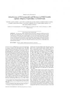
Fig. 7. OctArm V mounted on Foster-Miller TALON system.
III. FIELD TRIALS A. Test Site Description The OctArm/Talon system underwent extensive field trials in the spring of 2005 at the Southwest Research Institute (SwRI) in San Antonio, Texas. The SwRI testbed is specially designed for the systematic evaluation of robotic systems in the field. The test environment includes rubble piles and a dry riverbed which can be flooded to create turbulent conditions. The main goal for the trials was to evaluate the ability of the OctArm system to stably and adaptively grasp a wide range of objects under a variety of conditions. B. OctArm Implementation Details For the field tests, OctArm V was mounted on a FosterMiller TALON platform (shown in Fig. 7). The OctArm base was attached to the second link of the TALON robot arm. The control valves and two air tanks provided nine channels of controlled pneumatic pressure. The control computer was mounted on the back of the TALON. The TALON and arm were controlled via wireless connection. A battery-powered on-board control computer serves as
Fig. 8. Cone stacking task.
2338
iary battery pack (36 VDC, 18Ah). The system was operated under joystick control via the wireless link and in view of the operator. More details of the user interface used are described in [6].
Fig. 9. Grasp in turbulent water.
the hardware platform for the robot control system. This is a commercial off-the-shelf Pentium III EBX form-factor Single Board Computer (SBC) with data acquisition electronics for analog and digital I/O, housed in an environmentally sealed cabinet for protection from vibrations, dust and dirt typically encountered outdoors. The computer runs the QNX® Neutrino® real-time Operating System and in-house developed hard real-time control software for implementation of the control algorithms. The SBC enables untethered remote teleoperation of the continuum robot from an Operator Control Unit (OCU) consisting of a laptop running Windows® XP interfaced with a USB joystick. The communication link between the OCU and the onboard computer is a point-to-point wireless RF link (IEEE 802.11b). The OCU provides a graphical display built on the Coin3D graphics rendering library for a real-time 3D visualization of the robot shape to the operator. Based on operator inputs from the joystick, the trajectory updates for the robot are computed by a Matlab/Simulink-based program running on the OCU. The on-board computer provides a mission time of approximately 5 hours when powered by the Talon auxil-
Fig. 10. System alongside rubble pile.
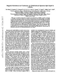
B. Task Descriptions Initial tasks included stacking and unstacking traffic cones (see Fig. 8.). The ability of the system to grasp objects such as spheres and cylinders over a wide range of scales was recorded. These tasks are inherently problematic for traditional parallel jaw end effectors. The operations were timed, and the operations videotaped and recorded in detail, to provide a baseline performance measure for continuum robots under the above conditions. The system was also operated in water. The OctArm was submerged in water (shown in Fig. 9), while attempting to grasp various payloads and to maintain grasps under turbulent flow. This tested the potential of the system for robust grasping under disturbances. The system was also operated alongside rubble piles (as shown in Fig. 10). This provided an initial benchmark for remote operation in congested environments. C. Task Outcomes The system was able to successfully stack and unstack cones (Fig. 8). Various sized cylinders and spheres (Fig. 11)
Fig. 11. Grasp of a medium sphere (top). Grasp of a large sphere (bottom).
2339
were grasped and manipulated. The system was able to successfully conform to the varying shapes of these payloads, demonstrating an ability to adapt to environmental conditions not found in traditional manipulators. The continuum system was able to successfully grasp both spherical (balls) and elongated objects (pieces of wood) within the underwater environment, and to maintain the grasps despite significant flow (Fig. 12). Remote teleoperation within the rubble pile was attempted. However, the lack of shape sensing (see below) proved a problem for the operator, who was unable to accurately infer the location of the trunk tip. Additionally, some objects were dropped due to a combination of lack of grip strength/grasp stability and the inability of the operator to correctly infer the shape of the robot. Note that the continuum arm in these trials featured no shape sensing, with the shape displayed to the user (via the VRML model) inferred only from the pressures at the actuator input valves. This proved to be a highly inaccurate estimate, as external effects such as sag due to gravity or external loading were not accounted for in any way. Since the trials described in this section, we have integrated shape sensors into the design to help reduce this problem.
IV. SUMMARY AND CONCLUSIONS The soft robot manipulator OctArm is constructed using air muscle extensors with three control channels per section that provide two axis bending and extension. Within each section, mesh and plastic coupler constraints prevent extensor buckling. OctArm IV is comprised of four sections connected by endplates, providing twelve degrees of freedom. Using only 4.13 bar of air pressure, the dexterous distal section provides 66% extension and 380ƕ of rotation in less than .5 seconds. OctArm V is comprised of three sections and, using 8.27 bar of air pressure, the strong proximal section provides 890 N and 250 N of vertical and transverse load capacity, respectively. The OctArm continuum robots successfully grasped and manipulated objects over a wide range of sizes and scales, demonstrating the ability to adapt their shape to that of a wide variety of payloads. Additionally, the tests demonstrated the ability of the continuum robots to operate successfully in the field, both in air and in water, and to maintain grasp stability under dynamic disturbances. Our ongoing efforts focus on enhanced designs incorporating significantly higher arm strength, and on the integration of sensors to guide remote operation in congested obstacle fields. REFERENCES [1] [2]
[3] [4] [5] [6]
[7] [8] [9] [10] [11] [12] [13] Fig. 12. Grasp of elongated object in water (top). Grasp of medium sphere in water (bottom).
2340
V.C. Anderson and R.C. Horn, “Tensor Arm Manipulator Design,” ASME Paper 67-DE-57, 1965. T. Aoki, A. Ochiai, and S. Hirose, “Study on Slime Robot,” Proceedings IEEE International Conference on Robotics and Automation, New Orleans, 2004, pp. 2808-2813. R. Buckingham and A. Graham, “Reaching the Unreachable - Snake Arm Robots,” Proceedings International Symposium of Robotics, Chicago, 2003. G.S. Chirikjian, “Theory and Applications of Hyperredundant Robotic Mechanisms,” Ph.D. thesis, Department of Applied Mechanics California Institute of Technology, 1992. R. Cieslak and A. Morecki, “Elephant Trunk Type Elastic Manipulator A Tool for Bulk and Liquid Type Materials Transportation,” Robotica, Vol. 17, 1999, pp. 11-16. M. Csencsits, B.A. Jones, W. McMahan, V. Iyengar, and I.D. Walker, “User Interfaces for Continuum Robot Arms,” Proceedings IEEE/RSJ International Conference on Intelligent Robots and Systems (IROS), Edmonton, Canada, 2005, pp. 3011-3018. I. Gravagne, C.D. Rahn, and I.D. Walker, “Large Deflection Dynamics and Control for Planar Continuum Robots,” IEEE/ASME Transactions on Mechatronics, Vol. 8, No. 2, pp. 299 — 307, June 2003. M.A. Hannan and I.D. Walker, “Kinematics and the Implementation of an Elephant's Trunk Manipulator and Other Continuum Style Robots,” Journal of Robotic Systems, Vol. 20, No. 2, 2003, pp. 45-63. S. Hirose, Biologically Inspired Robots, Oxford University Press, 1993. G. Immega and K. Antonelli, “The KSI Tentacle Manipulator,”. Proceedings 1995 IEEE International Conference on Robotics and Automation, pp. 3149--3154, 1995. W.M. Kier and K.K. Smith, “Tongues, Tentacles, and Trunks: The Biomechanics of Movement in Muscular-hydrostats,” Zoological Journal of the Linnean Society, Vol. 83, pp. 307-324, 1985. W. Liu and C.D. Rahn, “Fiber Reinforced Membrane Models of McKibben Actuators,” ASME Journal of Applied Mechanics, Vol. 70, No. 6, pp. 853-859, Nov. 2003. W. McMahan, B.A. Jones, and I.D. Walker, “Design and Implementation of a Multi-Section Continuum Robot: Air-Octor,” Proc. IEEE/RSJ International Conference on Intelligent Robots and Systems (IROS), Edmonton, Canada, 2005, pp. 3345-3352.
[14] H. Ohno and S. Hirose, “Design of Slim Slime Robot and its Gait of Locomotion,” Proceedings IEEE/RSJ Int. Conference on Intelligent Systems, Maui, Hawaii, USA. 2001, pp. 707-715. [15] M.B. Pritts and C.D. Rahn, “Design of an Artificial Muscle Continuum Robot,” Proceedings IEEE International Conference on Robotics and Automation, New Orleans, 2004, pp. 4742-4746. [16] G. Robinson and J.B.C. Davies, “Continuum Robots - A State of the Art,” In Proceedings 1999 IEEE Conference on Robotics and Automation, pages 2849-2854, 1998. [17] N. Simaan, R. Taylor, and P. Flint, “A Dexterous System for Laryngeal Surgery,” Proceedings IEEE International Conference on Robotics and Automation, New Orleans, 2004, pp. 351-357. [18] K. Suzumori, S. Iikura, amd H. Tanaka, “Development of Flexible Microactuator and its Applications to Robotic Mechanisms,” Proceedings IEEE International Conference on Robotics and Automation, Sacramento, CA, 1991, pp. 1622-1627. [19] H. Tsukagoshi, A. Kitagawa, and M. Segawa. “Active Hose: an Artificial Elephant's Nose with Maneuverability for Rescue Operation,” Proceedings IEEE International Conference on Robotics and Automation, Seoul, Korea, 2001, pp. 2454-2459. [20] I.D. Walker, D. Dawson, T. Flash, F. Grasso, R. Hanlon, B. Hochner, W.M. Kier, C. Pagano, C.D. Rahn, and Q. Zhang, “Continuum Robot Arms Inspired by Cephalopods,” Proceedings SPIE Conference on Unmanned Ground Vehicle Technology VII, Orlando, FL, March 2005, pp 303-314. [21] J.F. Wilson, D. Li, Z. Chen and R.T. George, “Flexible Robot Manipulators and Grippers: Relatives of Elephant Trunks and Squid Tentacles,” In Robots and Biological Systems: Towards a New Bionics? pp. 474-494, 1993.
2341