Filter-VW. Unit Description. Filter-VW (v 2.6) unit (hereinafter referred to as “the
unit”) is designed for VW Touareg (2003-2010),. VW Multivan T5, VW Passat B6,
...
«Filter-VW» Technical Manual
www.TEC-electronics.ru/en/
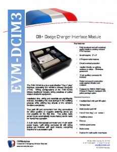
TEC-6405-13 Technical Manual Filter-VW Unit Description�������������������������������������������������������������������������������������������������������������� 2 Unit connection��������������������������������������������������������������������������������������������������������������� 2 Table 1. Unit port outputs assignment.������������������������������������������������������������������������������ 3 Особенности подключения�������������������������������������������������������������������������������������������� 3 Table 2. Technical data and operation conditions���������������������������������������������������������������� 4 Table 3. Standard delivery kit������������������������������������������������������������������������������������������� 4 Unit Description Filter-VW (v 2.6) unit (hereinafter referred to as “the unit”) is designed for VW Touareg (2003-2010), VW Multivan T5, VW Passat B6, Porsche Cayenne (2004-2009). The unit’s purpose is to remove the blocking of video feed on the original monitor, which is automatically blocked when the car starts moving. The unit is connected to the CAN-bus breakage and interfaces with it on hardware and software levels. The unit is fully transparent for both the vehicle and diagnostic equipment and does not interfere with the vehicle electronic equipment operation and original video system control and functioning. The unit can operate in one of two modes: active (ON) and passive (OFF). The unit can be activated and deactivated with or original buttons (for VW Multivan T5, VW Passat B6, Porsche Cayenne (2003-2009)) and original button (for VW Touareg (2003-2010)) located on the steering wheel, or a specially installed alternative button. Below any of these buttons is mentioned as “controlling button”. Original button saves its primary function regardless of the unit operation mode. Unit activation and deactivation is carried out with long pressing of the controlling button (for no less than 2 sec) when the ignition is ON. Activated unit removes video feed blocking from the original screen without interfering with other equipment’s operation. Deactivated unit retransmits CAN-bus signals without changing them. In the meantime, vehicle equipment operation including the display is carried out in accordance with original algorithms. Information about unit operation mode is stored in permanent memory and its condition will not change should the power be deactivated. LED is used for indicating the unit’s condition. It can be installed in any area or not installed at all. If the unit is OFF or the ignition is OFF then LED is always OFF. When switching the unit ON the LED turns ON for no less than 4 sec then shuts down. The LED indicates that the unit is ON by lighting with every pressing of control button for the time it is pressed and also by lighting for 4 sec when switching the ignition ON. For all the other cases, the LED is always OFF. When the CAN-bus switches to hibernation mode, the unit enters the energy saving (standby) mode regardless of whether it is ON or OFF. It is recommended to switch the unit OFF in case of: putting the car on maintenance in the service station, or when you need to use the standard navigation system and while you do not need to use the unit. Unit connection CAN bus is a twisted pair wire composed from orange-brown CAN-L and orange-violet CAN-H wires. The unit is connected in this bus’s breakage at the monitor’s port. Unit port outputs numeration is shown in Fig. 1. 18
10
9 1 Fig. 1 U � nit port outputs numeration, from the wiring viewpoint.
Outputs assignment is shown in Table 1.
2
www.TEC-electronics.ru/en/
TEC-6405-13 Technical Manual Filter-VW Table 1. Unit port outputs assignment. No 1 2 3 4 5 6 7 8 9 10 11 12 13 14 15 16 17 18
Wire Color Black Brown Brown Green/Black Green/White Red Brown/Red Brown/Red Green -
Type Power supply CAN 2 CAN 1 (-) Output (-) Input Power supply CAN 2 CAN 1 (+) Output -
Assignment «Ground» CAN-L vehicle data bus CAN-L vehicle data bus To the blue wire of the LED Alternative unit activation/deactivation button +12V unit supply CAN-H vehicle data bus CAN-H vehicle data bus To the red wire of LED -
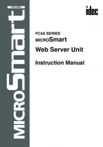
CAN 1 unit’s wire pair is connected with CAN bus from the vehicle’s side, while CAN 2 unit’s wire pair is connected to the bus from the monitor’s side. Brown wires of the unit are connected with orange-brown wires of the vehicle, while brown-red wires of the unit are connected with orangeviolet wires of the vehicle. The black wire of the unit coming from the contact No. 1 of the unit port is connected to the vehicle body in the areas defined by manufacturer for connection of the original electrical equipment ground. Unit’s red wire is connected to the one of the car wires with +12V constant voltage. Green/white wire is connected to vehicle’s ground via normally open alternative control button in case when the button installation is necessary Особенности подключения If CAN bus is connected to the monitor with duplex twisted wire pair (e.g., in VW Touareg vehicles), i.e. monitor port’s contacts are acting as the bus splitter (see Fig. 2) Orange/Brown CAN-L
Orange/Violet CAN-H Fig. 2. C � AN bus contacts location in monitor’s port in VW Touareg, VW Multivan T5, VW Passat B6 vehicles.
then it is necessary to disconnect both pairs from the monitor and carry out the connection as per diagram shown in Fig. 3.
www.TEC-electronics.ru/en/
3
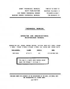
TEC-6405-13 Technical Manual Filter-VW
Fig. 3. Full duplex CAN bus breakage diagram
Table 2. Technical data and operation conditions Characteristic Voltage, V Max. current in working mode, mA Max. current in standby mode, mA Temperature, ˚C Relative humidity, %
Data 9 ... 15 200 1,5 – 40 ... + 85 95
Table 3. Standard delivery kit Item Central unit Cable harness with terminal Technical Manual LED indicator with wiring User memory card Package
Q-ty 1 1 1 1 1 1
pc pc pc pc pc pc
Product warranty is provided for 1 year since the moment of the sale if all the installation recommendations have been followed. In case of warranty case please contact to the company which sold this product to you. Distributor _____________________________ Date of sale __________________________
O 4
Manufacturer «TEC electronics» Ltd. Product is produced according to ТУ 4372-006-78025716-10. Certificate of origin No РОСС RU.AB75.B00340 Product corresponds to regulatory documents: ГОСТ Р 41.97-99, ГОСТ Р 50789-95
www.TEC-electronics.ru/en/