University, and Kevin Davis, now at Reaction Engineering International, in Salt Lake City, served ..... A Suntec mechanical pressure regulator was used. Nozzles ...
SAND99-8238 Unlimited Release Printed April 1999 COMBUSTION PROPERTIES OF BIOMASS FLASH PYROLYSIS OILS
Final Project Report Christopher R. Shaddix and Donald R. Hardesty Combustion Research Facility Sandia National Laboratories Livermore, CA 94550 with a supplement provided by Steven Gust Neste Oy Porvoo, Finland Abstract Thermochemical pyrolysis of solid biomass feedstocks, with subsequent condensation of the pyrolysis vapors, has been investigated in the U.S. and internationally as a means of producing a liquid fuel for power production from biomass. This process produces a fuel with significantly different physical and chemical properties from traditional petroleum-based fuel oils. In addition to storage and handling difficulties with pyrolysis oils, concern exists over the ability to use this fuel effectively in different combustors. Preliminary trials in boilers, diesel engines, and turbine combustors have shown poor ignition behavior and high emissions of CO and particulate. However, the effects of spray parameters and pyrolysis oil properties on the observed behavior have not been delineated clearly. Over the past few years, Sandia National Laboratories has been funded by the U.S. Department of Energy (DOE), through DOE’s Biomass Power Program and the National Renewable Energy Laboratory (NREL), to investigate the effects of pyrolysis oil properties on their combustion behavior. This work has utilized an entrained-flow, droplet combustion facility to evaluate the combustion characteristics of a variety of biomass oils produced by fast pyrolysis, focusing on those produced by NREL in a pilot-scale ablative vortex reactor. The oils investigated possess a wide range of water and char contents, were subject to various extents of pyrolysis severity, and were derived from several different feedstocks. This report serves as a summary of the comprehensive research activity completed at Sandia’s Combustion Research Facility and also summarizes the current status of pyrolysis oil combustion research activities worldwide. The report endeavors to place the results and conclusions from Sandia’s research into the context of international efforts to utilize pyrolysis oils. As a special supplement to this report, Dr. Steven Gust, of Finland’s Neste Oy, has provided a brief assessment of pyrolysis oil combustion research efforts and commercialization prospects in Europe.
3
Table of Contents
Page
Abstract................................................................................................ 3 Table of Contents..................................................................................... 4 List of Figures ........................................................................................ 6 List of Tables ......................................................................................... 8 Nomenclature ......................................................................................... 8 Executive Summary.................................................................................. 9 Introduction ..........................................................................................11 Liquid Fuels from Biomass .....................................................................11 Pyrolysis Oil Production ........................................................................12 Physical and Chemical Properties of Pyrolysis Oils .........................................13 pH ...............................................................................................15 Oxygen content ................................................................................15 Water content ..................................................................................15 Volatility distribution..........................................................................18 Heating value ..................................................................................18 Viscosity........................................................................................19 Atomization properties ........................................................................20 Char content....................................................................................21 Survey of Pyrolysis Oil Combustion Research...............................................21 Boilers ..........................................................................................23 Diesel engines..................................................................................24 Gas turbines....................................................................................24 Biomass Fuel Combustion System................................................................25 Droplet Burning Rates ...........................................................................27 Results and Discussion .............................................................................28
4
Table of Contents (continued)
Page
NREL Pine and Oak Oils........................................................................31 NREL Switchgrass Oil and Poplar Oil 160 ...................................................32 Improved NREL Poplar Oils....................................................................34 Pyrolysis Oil/Water/Alcohol Mixtures .........................................................36 Ensyn Oak Oil ....................................................................................38 Implications for Practical Applications............................................................39 Pyrolysis Oil Droplet Burning Rates...........................................................40 Droplet Microexplosion and Cenosphere Formation.........................................42 Conclusions..........................................................................................46 Acknowledgments...................................................................................47 List of References ...................................................................................48 Project Presentations and Publications............................................................54 Supplement: Combustion of Pyrolysis Oils in Europe.........................................56 Driving Forces in Europe........................................................................56 Critical Issues for Applications .................................................................56 Fuel Prices and Pyrolysis Use..................................................................57 Resource Base ....................................................................................58 Combustion Technology ........................................................................58 Combustion System Modifications.............................................................58 Samples Tested ...................................................................................58 Combustion Results and Comparison .........................................................59 Diesel Experiences ...............................................................................60 Pyrolysis Quality Improvements ...............................................................60 Conclusions.......................................................................................61
5
List of Figures
Page
Figure 1:
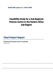
Schematic of the NREL ablative vortex reactor for producing biomass pyrolysis oils. Temperatures and characteristic residence times are noted throughout the process. Two different types of hotgas filtration are indicated for removing entrained char particles from the pyrolyzer exhaust flow: the earlier NREL oils were produced with the cyclone separators, whereas later oils were produced using a high-temperature baghouse. [Schematic based on figures in Czernik et al., 1995, and Diebold and Scahill, 1997, and personal communication from John Scahill, NREL.] ............................................14
Figure 2.
Schematic of Sandia’s Biomass Fuel Combustion System (BFCS). ................26
Figure 3.
Time-exposure photographs of the combustion of diesel No. 2 oil and various biomass pyrolysis oils in Sandia’s laminar-flow, singledroplet combustion reactor. The nominal reactor conditions for the photographs shown here are 1500 K and 24 mole-% O2, with initial droplet diameters of ≈ 350 µm............................................................28
Figure 4.
Interpretive description of time-exposure droplet combustion photograph for the particular case of NREL poplar oil No. 175......................30
Figure 5.
Backlit, high-magnification stroboscopic images of NREL pine oil No.150 droplets undergoing primary microexplosion in the BFCS under the conditions given for Fig. 3. The ticks on the left of these and all succeeding stroboscopic images are separated by 100 µm, giving the physical scale of the images. The initial droplet size was ≈ 350 µm....................................................................................31
Figure 6.
Backlit, high-magnification stroboscopic images of NREL oak oil No. 154 droplets undergoing primary microexplosion in the BFCS under the conditions given for Fig. 3. The initial droplet size was ≈ 350 µm. .....................................................................................32
Figure 7.
Variation of the square of the droplet diameter with residence time in Sandia’s BFCS at nominal conditions of 1600 K and 24 mole-% O2. The droplet diameters are normalized by the initial droplet diameter, in order to enhance the comparison of the results for different fuels. The initial diameters are ≈ 350 µm. For clarity the residence time zero is offset by 40 msec for poplar oil No. 160 and 140 msec for switchgrass oil. The lines shown are linear fits of the data judged to be in a d2-law regime. Microexplosions are denoted by asterisks..................................................................................33
6
List of Figures (continued)
Page
Figure 8.
Backlit, high-magnification stroboscopic images, obtained in Sandia’s BFCS, of NREL switchgrass oil No. 157 droplets undergoing primary microexplosion. The initial droplet size is ≈ 350 µm. .....................................................................................34
Figure 9.
Backlit, high-magnification stroboscopic images, obtained in Sandia’s BFCS, of NREL poplar oil No. 160 droplets undergoing primary microexplosion. The initial droplet size is ≈ 350 µm........................34
Figure 10.
Backlit, high-magnification stroboscopic images, obtained in Sandia’s BFCS, of NREL poplar oil No. 174 droplets undergoing primary microexplosion. The initial droplet size is ≈ 350 µm........................35
Figure 11.
Backlit, high-magnification stroboscopic images, obtained in Sandia’s BFCS, of NREL poplar oil No. 175 droplets undergoing primary microexplosion. The initial droplet size is ≈ 350 µm........................35
Figure 12.
35-mm, long-exposure photographs of the droplet combustion of pure NREL poplar oil and selected oil/water/methanol mixtures in the BFCS at 1600 K and 24 mole-% O2. ...............................................37
Figure 13.
Backlit, high-magnification stroboscopic images of droplet microexplosions, obtained in Sandia’s BFCS, during the combustion of Ensyn oak oil, NREL poplar oil, and various poplar oil/water/alcohol mixtures. Initial droplet diameters are 440 µm for the Ensyn oil and 390 µm for the NREL oil and the mixtures. .......................39
Figure 14.
Schematic representations of (a) the temperature, and (b) the molar concentration of more volatile components, as a function of the droplet mass loss during combustion of a multicomponent droplet with a wide range of volatilities. These figures are derived from Law (1989) for a liquid Lewis number of 30, modifying the temperature range and variation to reflect a typical volatility range for pyrolysis oils................................................................................43
Figure 15.
Plots demonstrating (a) the increase in boiling point of some representative components of pyrolysis oils as a function of ambient pressure (data from Reid et al., 1987), in contrast to (b) the relative insensitivity of the superheat limit (of the more volatile compounds) (data from Avedisian, 1985). .............................................................45
Figure S-1.
Bar chart of 1998 estimated production costs and imposed taxes for light fuel oil (LFO) and heavy fuel oil (HFO) in the U.S. and several European countries. Costs are given in ECU (the predecessor of the euro) per liter................................................................................57
7
List of Tables
Page
Table 1.
Chemical and Physical Properties of Conventional and Biomass Flash Pyrolysis Oils Investigated by Sandia ............................................16
Table 2.
Chemical and Physical Properties of Other Biomass Flash Pyrolysis Oils...............................................................................17
Table 3:
Combustion Research with Flash Pyrolysis Oils.......................................22
Table S-1:
Flash Pyrolysis Liquid Properties and Emissions Compared to Alternative Fuels............................................................................59
Nomenclature CO CO2 H2O
carbon monoxide carbon dioxide water
NOx O2
Bh,c Bh,v cp d Dl ∆P Kc Kv Lel M m˙ m˙ a m˙ f
combustion heat transfer number vaporization heat transfer number specific heat of the gas droplet diameter molecular diffusivity of the liquid pressure drop droplet combustion rate constant droplet evaporation rate constant Lewis number of the liquid droplet non-dimensional mass loss mass flowrate mass flowrate of air mass flowrate of fuel
m˙ v Pel qc qv r
αl
thermal diffusivity of the liquid thermal conductivity of the gas absolute viscosity kinematic viscosity mass density droplet liquid mass density surface tension stoich. mass fraction of oxidizer to fuel stoich. mass fraction of air to fuel droplet burnout time
λ µ ν ρ ρl σ σO σ ox τ
nitric oxides; the sum of NO and NO2 molecular oxygen
droplet mass evaporation rate Peclet number of the liquid specific combustion enthalpy specific vaporization enthalpy droplet radius r0 initial droplet radius Tamb ambient, far-field temperature far-field temperature T∞ droplet temperature Tl YH2O mass fraction of water in oil YO,∞ oxidizer mass fraction in the far field
8
Executive Summary As part of the U.S. DOE Biomass Power Program, Sandia National Laboratories investigated the combustion properties of a number of biomass pyrolysis oils over a 5-year period, focussing on those produced at the National Renewable Energy Laboratory (NREL) using a pilot-scale, ablative vortex reactor. This final report summarizes the findings of this research and places them in the context of the continuing international effort to develop biomass pyrolysis oils as a renewable energy source for liquid fuel applications. The production of a liquid fuel by pyrolysis of biomass offers several distinct advantages over conventional biomass combustion or gasification. The alkali and other mineral components of the feed are predominately captured in the char residue from the pyrolysis, resulting in a clean liquid biomass fuel that may be fired in high-efficiency diesel engines or gas turbines. Also, the liquid state of the fuel allows for separation of the location of the pyrolysis plant (in proximity to the feedstock source) and the location of needed power production. Unfortunately, there are several chemical and physical properties of pyrolysis oils that result in difficulties in storage and handling and also adversely affect their combustion properties. Pyrolysis oils are characterized by their acidity, low energy value, high viscosity, and instability. Research at NREL and elsewhere has demonstrated that the oil viscosity and instability may be reduced through the use of advanced hot-gas filtration techniques during pyrolysis oil production, as well as the use of inexpensive chemical additives (such as water or methanol) to the pyrolysis oil. Even with these improvements to the oil properties, concern over combustion applications exists, on account of the high water content, high oxygen content, wide volatility distribution, and presence of char in the pyrolysis oil — these factors negatively impact the atomization, ignition, coking tendency, and emissions associated with burning this fuel. Worldwide, limited pilot-scale combustion testing has been performed with pyrolysis oils in furnaces and boilers, diesel engines, and gas turbine combustors. In boiler applications, preheating of the near-burner refractory has been required for suitable ignition of the pyrolysis oil, and CO and particulate emissions have been high. In diesel engine applications, acceptable ignition quality has only been achieved when using substantial air preheat, pilot ignition with diesel fuel, or an extensive amount of cetane improver in the pyrolysis oil. In addition, engine emissions of CO, hydrocarbons, and soot have been significant. Similar trends have been evident when firing pyrolysis oils in gas turbines. Surprisingly, in spite of the poor ignitability and the high water content of the pyrolysis oils, their overall burning rates in these combustors appear to be similar to those of conventional fuel oils. Sandia’s research on biomass pyrolysis oil combustion focussed on the comparative analysis of the combustion properties of standard petroleum fuel oils and pyrolysis oils produced from several different feedstocks and with a variety of oil properties. Pyrolysis oils produced from oak, pine, switchgrass, and poplar were investigated, with water contents varying from 16–30 wt-% and alkali contents ranging from ≈ 10–900 ppm. In addition, mixtures of a pyrolysis oil with methanol/ethanol and/or water were investigated. Combustion characterization was performed in a laminar, entrained droplet flow reactor, maintained at a temperature of ≈ 1500 K, with lasertriggered strobe-backlight imaging and a collection probe. This apparatus permitted the quantitative determination of the characteristic fuel burning rate, as well as qualitative evaluation of the fuel combustion process and the coking tendency of the fuel.
9
The measurements at Sandia revealed that the droplet combustion rates of pyrolysis oils are substantially lower (by a factor of 2–3) than that of a light fuel oil. A theoretical analysis demonstrated that the lower combustion rate primarily results from the high mass density and latent heat of vaporization of pyrolysis oils. However, due to the wide range of volatilities of the constituents of pyrolysis oils, burning pyrolysis oil droplets experience microexplosions that disperse the original droplet mass into a number of droplet fragments. This phenomenon plays an important role in reducing the overall burnout time of pyrolysis oils and in reducing or eliminating the production of coke cenospheres. The timing and effectiveness of droplet microexplosions were found to be dependent on the severity of the oil-producing pyrolysis process, the water content of the pyrolysis oil, and the amount of char suspended in the oil. No dependence of combustion behavior on biomass feedstock source was apparent. The addition of methanol or ethanol to a pyrolysis oil accelerated the timing of microexplosions, but did not increase their effectiveness. On the other hand, addition of water to a pyrolysis oil delayed the onset of microexplosion, but enhanced its effectiveness. For improvements in pyrolysis oil storage, handling, and general combustion properties, addition of methanol or ethanol is recommended. However, for those applications in which cenosphere formation or droplet burnout is problematic, water addition, preferably together with alcohol addition, is recommended. In practical applications of pyrolysis oil combustion, the droplet sizes are generally smaller than those investigated at Sandia, and the gas pressure will be significantly higher for the diesel engine and gas turbine applications. Under these conditions, droplet microexplosions will still occur and play an important role in the combustion of pyrolysis oils. However, the intensity and effectiveness of the microexplosions will likely be reduced under high pressure conditions. As enumerated in the attached supplement, provided by Finland’s Steven Gust, with the current status of petroleum-fuel taxes and renewable energy incentives in place in Europe, production and combustion of biomass pyrolysis oils for power and steam production is nearly economically feasible for some countries. In the U.S., pyrolysis oils are clearly not an economic alternative for power production at this time, except perhaps for application to a few remote, wooded locations where the price of delivered diesel fuel is very high and biomass feedstocks are readily available. In the future, rising petroleum costs and increased incentives for the use of indigenous, renewable resources may make pyrolysis oils a broadly applicable source of liquid fuels in the U.S. Irrespective of the economics, biomass oils currently have significant storage, handling, and combustion difficulties that limit their application. One possible method by which the combustionrelated shortcomings may be circumvented is to cofire pyrolysis oils with other fuels, analogous to the present thrust on the cofiring of solid biomass feedstocks with coal in large utility boilers. Because pyrolysis oils have poor miscibility with light petroleum fuel oils, the most suitable candidate fuels for direct fuel mixing are methanol or ethanol. Early mixing with methanol or ethanol has the added benefit of significantly improving the storage and handling properties of the pyrolysis oil. For separate-injection cofiring, as has been previously demonstrated in a dualinjection diesel engine, conventional petroleum fuel oils can be fired together with pyrolysis oils.
10
Introduction Biomass resources represent one of the most promising sources of renewable energy, both in the United States and internationally. With heightened attention recently focused on global climate change, the use of biomass to produce electrical power in a near-CO2-neutral fashion has become more important to many developed countries. In addition, increased use of biomass resources promotes rural development and full utilization of farmland, while reducing the quantity of material being landfilled. The U.S. contains substantial biomass resources, so full development of this indigenous fuel source promotes the creation of jobs in the U.S. and could reduce the trade deficit. Current use of biomass in the U.S. is dominated by relatively small, inefficient boilers firing wood waste for steam and power production in the forest products industry and by pulp mills burning black liquor (a combination of lignin, water, sodium, and sulfur) in chemical recovery boilers. For future development of significant electrical production from biomass, three thermochemical conversion technologies are envisioned: (a) direct combustion, especially in cofire applications with existing large-scale, relatively efficient coal power plants; (b) gasification, especially as part of an integrated gasification, combined-cycle (IGCC) powerplant, to yield optimal process efficiency; and (c) pyrolysis, with condensation of the devolatilized organic vapors to yield a fuel oil. Research and development of suitable technology in all three of these areas has been pursued by the U.S. Department of Energy’s Biomass Power Program (BPP). As a portion of the research into biomass pyrolysis oils for power production, Sandia National Laboratories has completed an investigation of the combustion properties of a variety of pyrolysis oils, primarily those produced by the small-scale ablative vortex reactor at the National Renewable Energy Laboratory (NREL). This report summarizes the combustion-relevant properties of biomass pyrolysis oils, the other combustion experiments that have been performed on pyrolysis oils, the findings of Sandia’s pyrolysis oil combustion research, and the implications for practical applications of pyrolysis oils for power generation. Through participation in the IEA Biomass Combustion Working Group, Sandia has developed and maintained contacts with other groups investigating pyrolysis oil combustion. As a special supplement to this report, Dr. Steven Gust of Neste Oy, based in Porvoo, Finland, has provided an assessment of the European view of the commercial market for pyrolysis oil combustion and a summary of his own experience with combustion of pyrolysis oils in practical combustors.
Liquid Fuels from Biomass Efficient, economical liquefaction of solid fuels has long been desired, in order to take advantage of the ease of storage and transportation associated with liquid fuels, as well as high-efficiency conversion methods of liquid fuels and the extensive liquid fuel energy market. In the case of biomass, the very low energy density of the initial solid fuel and the low conversion efficiency associated with conventional, direct combustion technology further motivates liquefaction. In addition, conversion of raw biomass to a pyrolysis oil allows effective removal of alkali components from the fuel, thereby avoiding the alkali deposition problems that complicate the direct combustion and gasification-based processes. There are three different forms of liquid fuels from biomass being actively developed in the U.S. The most prominent of these is ethanol production from fermentation of starch or sugar. Corn is the predominant field crop used for this purpose in the U.S., with wheat dominating in Canada. Current price subsidies on ethanol production have allowed its penetration into the motor fuel market as a partial substitute for gasoline and as a dedicated fuel for some urban fleets of ethanol
11
vehicles. In addition, mixtures of ethanol and conventional diesel fuel (e.g., “E-15 oxydiesel”) are being investigated as a replacement fuel for diesel in compression-ignition engines. Research is actively occurring in fermentation chemistry in an attempt to economically produce ethanol from a variety of lignocellulosic biomass, such as wood or grasses. A second form of liquid fuel from biomass is termed “biodiesel”. As the name suggests, biodiesel is suitable for replacement of conventional diesel fuel and is completely miscible with diesel fuel. Biodiesel is produced by reacting a vegetable oil with a simple alcohol in a trans-esterification process that reduces the original triglycerides into glycerol and fatty acid esters. The most common formulation is a reaction of soybean oil and methanol to produce methyl soyate. The conversion of raw vegetable oil to biodiesel is necessary in order to reduce the viscosity of the fuel (for proper spray atomization) and to eliminate polymerization during handling and firing of the fuel. For the most part, experimental tests of biodiesel use in conventional diesel engines have shown good success, particularly regarding low soot emissions. Through DOE’s Office of Transportation Technologies (OTT), Sandia has initiated an investigation into the combustion of several alternative fuels, including biodiesel, in an optically accessible diesel engine in order to understand differences in the engine combustion process that impact pollutant emissions from the engine exhaust. While the technical performance of biodiesel appears satisfactory, the near-term prospects for biodiesel competing economically in the U.S. with petroleum-based diesel are poor. The third form of liquid fuel produced from biomass is pyrolysis oil, formed by rapidly heating lignocellulosic biomass to drive off the organic volatile components, then condensing the fuel vapors into a fuel oil. While work in the U.S. under the DOE BPP has now ceased, this process is being developed worldwide using a variety of different reactors and feedstocks. Fuels produced by this process are variously referred to as biomass pyrolysis oils, bio-oils, or biocrude. Specific information about the production and properties of these biomass-derived fuels are included in this final project report. Economic prospects for near-term utilization of this fuel source in the U.S. are poor, both due to the significant cost involved in producing the fuel and due to difficulties in achieving high fuel quality, particularly with large-scale processes. In general, the market value of liquid fuels and their range of possible applications vary substantially with the oil viscosity and sulfur and ash content, as reflected by the ASTM standard specifications for petroleum fuel oil grades 1–6 (ASTM, 1992). For example, in the U.S. and Canada, tax-free consumer prices for a light fuel oil, such as No. 2, are typically 50% higher than those for heavy fuel oil (No. 6) (Diebold et al., 1996; Annual Energy Review 1997). This trend is further accentuated in Europe, where light fuel oil typically costs twice as much as heavy fuel oil (Diebold et al., 1996; Gust, this report). In terms of electrical power production, the most efficient use of a liquid fuel is in firing a gas turbine, normally using a No. 2 fuel oil with special limitations on sulfur, ash, and metal content (Moses and Bernstein, 1994). Therefore, the economics of power production from pyrolysis oils drive an emphasis on production of oils with a quality equivalent to a No. 2 fuel oil.
Pyrolysis Oil Production A substantial amount of research has been conducted over the past two decades elucidating the optimal conditions for producing a high-quality pyrolysis oil from biomass. This work has demonstrated that high heating rates (on the order of 104 K/s), short residence times at intermediate temperature (e.g., < 1s at 500–600°C), and rapid vapor quenching are required for effective conversion of the raw biomass (and its energy content) to a pyrolysis oil (Bridgwater and Cottam, 1992; Graham et al., 1994; Horne and Williams, 1996). Under these conditions, 65–75% of the original, dry biomass mass is converted to liquid, with the remainder split, more or less evenly, between solid char and noncondensible gases. Such oils are termed “flash” or “fast” pyrolysis oils, to distinguish them from the heavier, low-yield oils produced from low-temperature, long residence time processes (Maggi and Delmon, 1994).
12
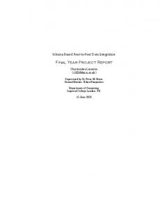
A number of different approaches have been investigated to achieve fast pyrolysis conditions, with different degrees of scale-up and commercial application possible (Bridgwater and Cottam, 1992). The most common reactor type has been a fluidized bed, but transported bed designs and ablative designs also have been successful. Ensyn Technologies Inc., based in Ontario, Canada, has produced the largest quantities of oil for physical and chemical characterization and combustion testing. The Ensyn RTP™ (rapid thermal processing) technique relies on a recirculating transported bed of sand to transfer heat rapidly to the feed particles (Graham et al., 1994). The predominant feedstock for Ensyn oils has been hardwood sawdust (esp. oak or maple). The next largest producer of flash pyrolysis oils has been Union Fenosa, a Spanish utility company, which utilizes a fluidized bed reactor derived from a design developed at the University of Waterloo in Ontario, Canada. Union Fenosa typically uses a eucalyptus feedstock. NREL has worked on development of an ablative vortex design for the pyrolyzer, in which the injected particles are abraded as they travel a helical path along the inside wall of the reactor (Czernik et al., 1995; Diebold and Scahill, 1997). For the pyrolysis oil combustion work performed at Sandia, NRELproduced oils were predominantly tested, because of their well-defined production conditions and the variety of feedstocks and particulate capture schemes used. A schematic of the NREL vortex reactor system is shown in Figure 1, to demonstrate the essential elements of a pyrolysis reactor unit and to clarify discussion later of the effect of different hot-gas filtration strategies on the character of the condensed pyrolysis oils. A common element of all fast pyrolysis reactors is active particle abrasion, either against other particles or the reactor wall, in order to expose fresh, reactive char surface during the short residence times available for pyrolysis to occur. One consequence of this process is the production of a large number of small char-particle fragments, often of micron-level size, that are entrained into the reactor product gas. For example, an analysis of the char particles exiting NREL’s vortex reactor has shown that over half of the particles are less than 3 µm in diameter, and 95% are less than 9 µm in diameter (Scahill, 1995). Without effective hot-gas filtration, these char particles are removed from the exhaust system with the condensed organic vapor stream and become part of the product fuel oil. Subsequent liquid filtration of the char from the oil is very difficult, due to the adherence of the viscous pyrolytic lignin portions of the oil to the char particles. High-efficiency cyclones are typically used by Ensyn to remove the entrained char particles, resulting in a final char content of ~ 1 mass-% in the oil. NREL introduced a baghouse for hot-gas filtration, in addition to cyclonic separators, resulting in a significant reduction in the char content of the collected oil, but increasing the secondary conversion of the pyrolysis vapors (Scahill et al., 1997).
Physical and Chemical Properties of Pyrolysis Oils There are a number of unique attributes of biomass pyrolysis oils that potentially lead to difficulties in applying them as combustion fuels. Consequently, a large body of work has been devoted to characterizing these oils. Biomass oils are composed of the thermal decomposition products of the mixture of cellulose, hemicellulose, and lignin composing the original biomass. The pyrolysis process generates a complex mixture of oxygenated organic compounds that span a wide range of molecular weights (esp. carboxylic acids, aldehydes, hydroxyketones, sugars, and phenolics) (Radlein et al., 1987; Evans and Milne, 1987a, 1987b; Maggi and Delmon, 1994; Meier et al.,
13
Bone-Dry Feed milled/screened (1/8" sieve) RECYCLE LOOP
FEED HOPPER (10 – 20 kg/hr)
N 2 Carrier Gas 700 °C 70 – 100 psi Carrier/Feed Mass Ratio = 1.2 – 2.0
to afterburner
SHELL-AND-TUBE HEAT EXCHANGERS
COALESCING FILTERS
Wall T = 625 °C 3 – 4 psig gas res. time = 0.3 s
Vapor Cracker 450–700 °C, 0.7 s 40 °C 100 °C
Secondary Cyclone
Primary Char Cyclone
BLOWER
Figure 1:
ABLATIVE VORTEX REACTOR
HOT-GAS FILTRATION
0 °C
COLLECTION VESSELS
idealized particle trajectory
EDUCTOR
CYCLONE CONDENSER
Vapor Exit T = 525 °C Baghouse 380 – 450 °C 3–6s
Transfer Leg
Schematic of the NREL ablative vortex reactor for producing biomass pyrolysis oils. Temperatures and characteristic residence times are noted throughout the process. Two different types of hot-gas filtration are indicated for removing entrained char particles from the pyrolyzer exhaust flow: the earlier NREL oils were produced with the cyclone separators, whereas later oils were produced using a high-temperature baghouse. [Schematic based on figures in Czernik et al., 1995, and Diebold and Scahill, 1997, and personal communication from John Scahill, NREL.]
1997; Milne et al., 1997). In addition, condensation reactions during pyrolysis produce water vapor, which is condensed together with the volatilized organic molecules during production of the oil. The large fraction of polar, oxygenated compounds in the condensed oil makes it miscible with the water produced during pyrolysis. Pyrolysis oils are thus miscible with alcohols and acetone, but largely immiscible with distillate fuel oils (Bakhshi and Adjaye, 1995). Measured physical and chemical properties of some flash pyrolysis oils and light and heavy fuel oils are shown in Table 1 and Table 2. For the NREL-produced oils, information on the material balance of the pyrolysis process for the different runs that produced the oils is also given. Table 1 lists the properties of the oils investigated in the combustion tests at Sandia. Properties of some other pyrolysis oils are given in Table 2. A detailed description of the most important properties of biomass oils for combustion applications follows. pH The presence of organic acids, thought to be dominated by acetic acid and formic acid, result in a pyrolysis oil pH of ~ 2.6–3.2 (equivalent to that of a typical soft drink or vinegar). As a consequence, pyrolysis oils cannot be stored, transported, or atomized in components made of conventional steel. Stainless steel and polypropylene effectively resist chemical attack from pyrolysis oil. Oxygen content The high oxygen content (both on a wet and dry basis) of pyrolysis oil results in a very low energy density (as quantified by the heating value), in comparison to conventional fuel oils. As a result, the volumetric firing rate of biomass oils must be significantly greater to maintain a given thermal output. However, the most important consequence of the organic oxygen content of pyrolysis oils is the resultant instability of the oil. Polymerization and condensation reactions involving the oxygen functionalities of the constituents of the oil lead to significant increases in the viscosity and water content of the oil over the course of weeks at room temperature and over the course of hours when maintained near 100 °C (Czernik et al., 1994; Diebold and Czernik, 1997). This property of biomass oils probably poses the most severe technical barrier to substantial commercial use of this fuel. Research has been conducted on hydrotreating bio-oils or cracking with a zeolite catalyst to remove the oxygen functionalities of the oil, but the process efficiency is poor and substantial technical barriers remain (Bridgwater and Cottam, 1992; Maggi and Elliott, 1997; Elliott and Neuenschwander, 1997; Conti et al., 1997). The most promising approach to reducing the rate of aging of the oils is to use simple fuel additives, such as water or methanol (Diebold et al., 1996; Maggi and Elliott, 1997). Methanol addition at the 10% level has been shown to decrease the rate of aging by about a factor of 20 (Diebold and Czernik, 1997). In addition, the suspended char particles catalyze the polymerization reactions, so improvements in char collection efficiency during oil production have led to more stable oils (Diebold et al., 1996; Diebold and Czernik, 1997). Water content In terms of the combustion process, several additional concerns exist over the properties of biomass oils. First, there is the substantial water content of the oils. By the nature of the pyrolysis process, at least 15% of the oil mass is composed of water. Depending on the existence of any water in the pyrolysis feed and the severity of the pyrolysis process, water can constitute over 30%
15
Table 1.
Chemical and Physical Properties of Conventional and Biomass Flash Pyrolysis Oils Investigated by Sandia NREL 150 Pine
NREL 154 Oak
NREL 157 Switchgrass
NREL 160 Poplar
NREL 174 Poplar
NREL 175 Poplar
Ensyn Oak
No. 2 oil
No. 6 oil
C
56.3
55.6
69.9
64.4
59.3
57.1
58.0
87.3
87.7
H
6.5
5.0
6.7
7.0
6.6
6.6
6.3
12.9
10.3
36.9
39.2
22.4
28.3
33.8
36.3
35.8
-0.3
1.2
0.3
0.1
1.0
0.3
0.19
0.04
0.0
55 wt-% dry oil) and resulted in pyrolysis oils with low water content (16–18 wt-%). The combination of high char loading and low degree of secondary thermal cracking of the pyrolysis vapors also resulted in pyrolysis oils with high adiabatic flame temperatures (1950–2100 K), approaching those of typical distillate petroleum fuel oils. The presence of char in these pyrolysis oils and the low water content resulted in high viscosity, particularly for the oak oil. Droplet combustion of all of the investigated NREL pyrolysis oils produced during this time period (circa 1993) demonstrated an early, but relatively ineffective, droplet microexplosion. The microexplosion produced some microfragments, but for the most part left the initial droplet intact, especially in the case of the oak oil (NREL 154). As a consequence, these pyrolysis oils showed disruptive, sooty burning following the first microexplosion and produced cenospheres near the bottom of the reactor (Wornat et al., 1994). Examples of images of the microexploding droplets are shown in Figures 5 and 6. In agreement with trends evident from later combustion experiments, the pine oil, with somewhat higher water content, experienced a later-occurring, more effective microexplosion than the oak oil. The early microexplosion occurrence for these
Figure 5.
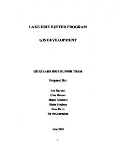
Backlit, high-magnification stroboscopic images of NREL pine oil No.150 droplets undergoing primary microexplosion in the BFCS under the conditions given for Fig. 3. The ticks on the left of these and all succeeding stroboscopic images are separated by 100 µm, giving the physical scale of the images. The initial droplet size was ≈ 350 µm.
31
Figure 6.
Backlit, high-magnification stroboscopic images of NREL oak oil No. 154 droplets undergoing primary microexplosion in the BFCS under the conditions given for Fig. 3. The initial droplet size was ≈ 350 µm.
pyrolysis oils precluded the determination of a droplet burning rate. Re-coalescence of the microexplosion-expanded oak oil droplets was determined to be largely complete within 5 msec after the microexplosion.
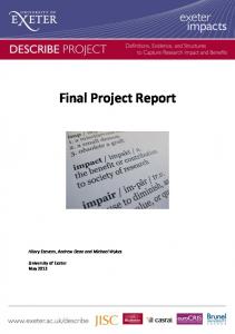
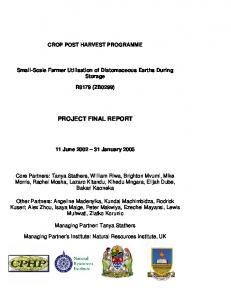
NREL Switchgrass Oil and Poplar Oil 160 The NREL switchgrass oil 157 and poplar oil 160 were two of the first bio-oils produced by NREL following introduction of their baghouse system in 1994 for hot-gas filtration of char fines entrained into the pyrolyzer exhaust flow. Consequently, the char loading in these oils was significantly reduced from the earlier oils, as evidenced by total alkali levels of ~ 25 ppm, total ash levels of 0.005–0.010 wt-%, and fixed carbon levels of 6–8 wt-%. However, in the initial operation of the baghouse, temperatures were conservatively maintained at 430–440 °C to prevent any condensation of the pyrolysis vapors (Diebold et al., 1994). These high temperatures, coupled with the long (5-s) residence time in the baghouse, resulted in significant secondary cracking of the pyrolysis vapors. Therefore, run yields were low (37% dry oil) and the water content of the biooils is very high (30 wt-%). In fact, the high water content of the switchgrass oil made it prone to separate into a light aqueous phase and a pyrolytic lignin fraction. The combustion behavior of both of these fractions was investigated, in addition to that of the homogenized switchgrass oil. The low char content and high water content resulted in bio-oils with relatively low viscosity (6 cSt at 40 °C, for the switchgrass oil) and low adiabatic flame temperatures (1760–1820 K). As shown in Fig. 3, both the homogenized switchgrass oil and poplar oil 160 exhibited a long period of quiescent burning (of ≈ 100 msec for 350-µm initial droplet diameters in 24% O2) before experiencing a sudden, violent microexplosion that completely shattered the droplet and lead to immediate droplet oxidation. The long quiescent burning period allowed the determination of droplet burning rates. "d2-law" plots are shown in Fig. 7 for the homogenized switchgrass oil, poplar oil 160, No. 2 diesel fuel oil, and residual fuel oil. All of these fuels demonstrated an initial droplet heat-up period during which the droplet diameter remained approximately constant. This period was followed by a roughly linear decrease in d2 as a function of residence time, with the local slope (i.e., burning rate) increasing with time. The linear fits shown in Fig. 7 yield droplet burning rates of 0.88 mm2/s for No. 2 oil, 0.43 mm2/s for No. 6 oil, 0.41 mm2/s for poplar 160 oil, and 0.29 mm2/s for switchgrass oil. For
32
comparison, Godsave determined the burning rates for ~ 1.5-mm sized droplets of a variety of pure liquid compounds and multicomponent fuels suspended from a silica filament (Godsave, 1953). His values for iso-octane (a gasoline simulant), kerosene, and diesel fuel are 0.95 mm2/s, 0.96 mm2/s, and 0.79 mm2/s, respectively. Similarly, Wood et al. (1960) reported droplet burning rates of 1.00 mm2/s and 0.90 mm2/s for 1.6-mm suspended drops of JP-4 and kerosene burning in air. JP-4 is a light aviation fuel with a volatility between gasoline and kerosene. Thus, for both of these studies there is a trend of decreasing burning rate with decreasing volatility, in keeping with the expression for the combustion heat transfer number, discussed earlier. Also, these values for petroleum-based fuels are consistent with the burning rate determined here for No. 2 diesel fuel oil. In particular, the lower burning rate for diesel fuel determined by Godsave is consistent with the slightly higher oxygen concentration (24 mole-% vs. 21 mole-%) and higher ambient temperature (1500 K vs. 300 K) for the entrained flow reactor experiments reported here.
1.0 poplar oil 160 0.8
switchgrass oil
(d/d0)2
No. 6 fuel oil 0.6 No. 2 fuel oil 0.4
0.2 0
40
80
120
160
200
240
Droplet residence time, ms Figure 7.
Variation of the square of the droplet diameter with residence time in Sandia’s BFCS at nominal conditions of 1600 K and 24 mole-% O2. The droplet diameters are normalized by the initial droplet diameter, in order to enhance the comparison of the results for different fuels. The initial diameters are ≈ 350 µm. For clarity the residence time zero is offset by 40 msec for poplar oil No. 160 and 140 msec for switchgrass oil. The lines shown are linear fits of the data judged to be in a d2-law regime. Microexplosions are denoted by asterisks.
Once initiated, the droplet microexplosions of the switchgrass and poplar 160 oils proceeded very rapidly (total duration < 500 µs) and were characterized by the formation of a single central bubble that shattered into a multitude of microdroplets, as shown in Figures 8 and 9.
33
Figure 8.
Backlit, high-magnification stroboscopic images, obtained in Sandia’s BFCS, of NREL switchgrass oil No. 157 droplets undergoing primary microexplosion. The initial droplet size is ≈ 350 µm.
Figure 9.
Backlit, high-magnification stroboscopic images, obtained in Sandia’s BFCS, of NREL poplar oil No. 160 droplets undergoing primary microexplosion. The initial droplet size is ≈ 350 µm.
The light aqueous phase of the switchgrass oil was found to burn in a weak quiescent flame with a very slow rate of surface regression. As is evident in Fig. 3, the heavy fraction of the switchgrass oil microexploded early in the droplet lifetime and the primary microexplosion was followed by secondary microexplosions as large droplet fragments were converted to solid coke particulates.
Improved NREL Poplar Oils Examination of the burning characteristics of NREL poplar oils 174 and 175 allowed a direct evaluation of the relative impact of pyrolysis unit cracking conditions (without variation in feedstock) on the combustion of the oil. Between NREL pyrolysis run No. 160 and run No. 174, improvements were made in lowering the temperature in the hot-gas filtration baghouse to ≈ 400 °C, reducing the extent of secondary cracking of the pyrolysis vapors (Diebold et al., 1996). For run No. 175, improved control of temperatures in the baghouse was maintained, resulting in even less secondary cracking. These trends are evidenced by the water content and dry oil pyrolysis yields shown for the three NREL poplar oils in Table 1. The char content dropped slightly from run No. 160, such that the total alkali level in oils No. 174 and 175 was ≈ 13 ppm. Viscosities for all 3 NREL poplar oils were between 10–20 cSt at 40°C.
34
As shown in Fig. 3, the combustion behavior of the poplar oil changed dramatically with the decreasing extent of pyrolysis vapor cracking, with poplar oils 174 and 175 microexploding earlier in the droplet lifetime and relatively less effectively than poplar oil 160 (Shaddix and Huey, 1997). In fact, the photograph of poplar 174 oil combustion shown in Fig. 3 was taken after chemical aging of the oil had begun to change its combustion characteristics. The original combustion behavior of this oil was very similar to that of the homogenized switchgrass. Figures 10 and 11 show typical images of droplet microexplosions for these poplar oils. Comparison of Figures 9–11 reveals a general trend of decreasing degree of droplet break-up during microexplosion in progressing from poplar 160 oil to poplar 175 oil. In fact, coke particulates were observed to be formed during the combustion of poplar oil 175 and its overall combustion characteristics were similar to those seen for combustion of the NREL oak oil. The primary
Figure 10. Backlit, high-magnification stroboscopic images, obtained in Sandia’s BFCS, of NREL poplar oil No. 174 droplets undergoing primary microexplosion. The initial droplet size is ≈ 350 µm.
Figure 11. Backlit, high-magnification stroboscopic images, obtained in Sandia’s BFCS, of NREL poplar oil No. 175 droplets undergoing primary microexplosion. The initial droplet size is ≈ 350 µm.
35
microexplosion for poplar oils 174 and 175 occurred too early to accurately determine a droplet burning rate.
Pyrolysis Oil/Water/Alcohol Mixtures As discussed in the introduction, promising results had been reported when adding water or simple alcohols to biomass pyrolysis oils in order to reduce their viscosity and their natural rate of aging. Therefore, there was interest in evaluating the effect of these additives on the pyrolysis oil combustion process. Also, the single droplet experiments for the various pyrolysis oils produced by NREL demonstrated that the extent of thermal cracking of the pyrolysis vapors during oil production had a profound effect on the timing and effectiveness of droplet microexplosion, and consequently on the droplet mass burnout profile. The degree of thermal cracking of the pyrolysis vapors is reflected in the water content of the biomass oils, so a separate investigation into the effect of water content on burning behavior was deemed to be important to determine the principal variables controlling the droplet microexplosion process. Consequently, NREL poplar oil 175, with low char content and low water content (21 wt-%), was used as the base fuel in a matrix study of blends with 0, 5, and 10% volume addition of water and/or methanol (Shaddix and Tennison, 1998). In addition, a single mixture of poplar oil and 5% ethanol was investigated, to compare the effect of using a simple alcohol with slightly lower volatility than methanol. Long-exposure photographs of the combustion history of the poplar oil and of a few of its mixtures with water and methanol are shown in Fig. 12. With the addition of 5% water and/or methanol, the effects on the combustion process are too small to definitively identify. However, with 10% addition of these compounds, some trends became apparent. For example, the addition of water delays the onset of droplet microexplosion, whereas the addition of methanol hastened its occurrence (verified by D2 plots derived from the backlit imaging). In addition, the spatial extent of the luminous flame produced during the microexplosion event increased for either water or methanol addition (usually an indication of more effective vaporization and micro-fragmentation of the droplet during the microexplosion). The extent and duration of post-microexplosion droplet-fragment burning did not appear to be affected significantly by methanol (or ethanol) addition alone, but were reduced with water addition or combined water and methanol addition. These observed trends are understandable, due to the differences in superheat limit temperatures and specific volume changes of water and methanol. Methanol is more volatile than the vast majority of the pyrolysis oil components, and has a low superheat limit of 190 °C (Avedisian, 1985). Although water is also more volatile than most of the oil constituents, it has a relatively high superheat limit of 302 °C. The improved microexplosion effectiveness with water addition probably resulted from the unique, high specific volume change of water upon converting from a liquid to a gas, which resulted in a much greater bubble expansion rate during the microexplosion. At the normal boiling point, the specific volume change of water is 1640, whereas it is 650 for methanol and varies from 200–600 for most common liquid compounds (Reid et al., 1987). Therefore, small amounts of water addition to the pyrolysis oil may be expected to be uniquely effective in enhancing the secondary atomization associated with droplet microexplosion. Plots of d2 vs. time for the mixtures do not show any significant effect on the droplet burning rate. For the pure poplar oil the burning rate increases from an initial value of 0.3 mm2/s to 0.5 mm2/s just before microexplosion, and these values also are seen at similar residence times for the mixtures. Figure 13 shows characteristic backlit images of microexploding drops of the poplar oil
36
100/0/0
95/5/0
95/0/5
90/5/5
90/10/0
80/10/10
Figure 12. 35-mm, long-exposure photographs of the droplet combustion of pure NREL poplar oil and selected oil/water/methanol mixtures in the BFCS at 1600 K and 24 mole-% O2. 37
and some of the mixtures. The poplar oil exhibits abrupt droplet shattering, with the production of a number of micro-fragments. However, a core mass of the original droplet is retained through the microexplosion process, resulting in the long streaks of luminous burning apparent in Fig. 12. With the addition of either water or methanol to the poplar oil, the microexplosion usually featured a sizable primary vapor bubble. With the addition of significant quantities of both water and methanol, the microexplosion process typically consisted of the growth of a single, central bubble up to a size of 2 mm over the course of ~ 2 ms before disintegrating. Finally, the addition of ethanol to the poplar oil resulted in microexplosions with 2 or 3 large fused bubbles that appeared to have a very textured surface. Analysis of the data from the combustion of the three NREL poplar oils revealed some correlation between the extent of bubble formation and the effectiveness of the microexplosion in breaking up the droplet (Shaddix and Huey, 1997). However, the results from the oil/water/alcohol blends revealed that the formation of large vapor bubbles during the primary microexplosion was not a sufficient condition for effective droplet breakup. The addition of methanol or other high-volatility compounds can be used to accelerate the occurrence of droplet microexplosions, but cannot be expected to improve the droplet break-up effectiveness of the microexplosion. The addition of water does improve the break-up effect of the microexplosion, particularly in conjunction with methanol addition. On the other hand, the combination of high water content and a significant concentration of low-volatility components (produced, for example, in an extended pyrolysis process) are required to yield the most effective droplet microexplosions. Unfortunately, in the fast pyrolysis process, the energy efficiency and the yield of bio-oil decrease significantly as the extent of secondary vapor cracking increases, due to the increased production of fixed gases.
Ensyn Oak Oil The Ensyn oak oil droplets initially demonstrated quiescent burning with a slightly blue flame before undergoing microexplosions (at a residence time of 36 ms). The early microexplosion is followed by the formation of a wide, umbrella-like “fan” of droplets or droplet fragments, burning with low levels of luminosity. The low luminosity during the post-microexplosion burning of this pyrolysis oil, in comparison with the luminous post-microexplosion burning of other biomass oils, probably resulted from the early occurrence of the microexplosion (preventing significant premicroexplosion drying of the droplet). Also, the early microexplosion of this oil precluded the determination of the droplet burning rate for this bio-oil, for comparison with NREL-generated bio-oils or conventional fuel oils. Figure 13 shows typical backlit images of microexploding Ensyn oak oil droplets. These microexplosions were of a very repeatable structure. Double-strobe imaging (500-µs interval) showed that a single dominant bubble was initially formed within the droplet, followed by the rapid formation of a cellular network of bubbles that first expanded and then began to contract within 1–2 ms of the initial bubble formation. The rapid spatial dispersion of droplets that was visually apparent after the microexplosion event presumably resulted from the jetting action of the pressurized vapor released during rupturing of one or more of these bubbles. Visual observation and backlit imaging suggested that coke particles were formed near the bottom of the reactor. The results of this investigation clearly show that the presence of char particles in pyrolysis oils accelerates the occurrence of droplet microexplosions. This would be a favorable characteristic, except that this early microexplosion is ineffective at dispersing the droplet mass, and char-laden pyrolysis oils have strong coking tendencies. Thus, in concurrence with considerations in the
38
areas of fuel handling and stability and atomization quality, good combustion behavior favors lowchar pyrolysis oils.
Ensyn oak oil (36 ms)
NREL poplar oil (58 ms)
95/5/0 mixture (60 ms)
90/10/0 mixture (74 ms)
80/10/10 mixture (66 ms)
95/0/5 ethanol mix (66 ms)
Figure 13. Backlit, high-magnification stroboscopic images of droplet microexplosions, obtained in Sandia’s BFCS, during the combustion of Ensyn oak oil, NREL poplar oil, and various poplar oil/water/alcohol mixtures. Initial droplet diameters are 440 µm for the Ensyn oil and 390 µm for the NREL oil and the mixtures.
Implications for Practical Applications Under the conditions of the Sandia droplet combustion experiments, microexplosions obviously play an important role in determining the heat release rate, droplet burn time, and the extent of cenosphere formation for a given biomass pyrolysis oil. However, as pointed out in the introduction, under practical firing conditions the dominant droplet mass is associated with
39
significantly smaller droplets than those investigated here. For these smaller droplets, the timescales associated with droplet heat-up and internal heat and mass transfer are much shorter, possibly affecting the tendency for occurrence of droplet microexplosions. Similarly, a significant fraction of the droplets in a practical combustor may vaporize within a region characterized by group combustion (Sirignano, 1983; Chen and Gomez, 1997), rather than single-droplet combustion, reducing the rate of heat transfer to the droplet and thus the tendency to microexplode. On the other hand, the high-pressure combustion conditions characteristic of gas turbines and diesel engines tend to enhance the occurrence of droplet microexplosions, but reduce their intensity (Lasheras et al., 1984; Wang and Law, 1985). Clearly, an evaluation of the effects of these practical firing conditions is needed in order to extrapolate the lab-scale droplet combustion results to actual applications. The conceptual elements of such an evaluation are described in the remainder of this section.
Pyrolysis Oil Droplet Burning Rates The portion of the pyrolysis oil droplet combustion history exhibiting classic, d2-law behavior is very small under the conditions of our droplet experiments, due to an extensive droplet heat-up region and due to the early occurrence of droplet microexplosion. In practical applications, with predominately smaller droplets and higher droplet Reynolds numbers (i.e., convective droplet vaporization), the proportion of the droplet lifetime associated with initial droplet heating will be reduced, leading to a more significant d2-law regime (Megaridis and Sirignano, 1992). As noted in the results section, the measured burning rates for pyrolysis oils ranged from ≈ 0.3 mm2/s (shortly after the droplet heat-up period) to 0.5–0.6 mm2/s at later residence times. The lower values of the burning rate are presumably dominated by the effects of preferential vaporization of the more volatile components, especially water, early in the combustion history. In order to identify and quantify the factors contributing to the relatively poor burning rate of pyrolysis oils, the theoretical expressions for droplet evaporation and burning rates (discussed in the introduction) were analyzed for diesel fuel, water, pyrolysis oils, and oil/water and oil/alcohol mixtures. The relevant equations used for these calculations are summarized below: Kv =
Kc =
(
(
)
8 λ cp c p (Tamb − Tl ) ⋅ ln1 + ρl qv
)
(
(10)
)
8 λ cp c p (T∞ − Tl ) + YO,∞ σ O qc ⋅ ln1 + ρl qv
(11)
Kv and Kc represent the droplet surface regression rates under non-combusting and combusting conditions, respectively, and are referred to as the evaporation and burning rate constants. The remainder of the symbols used in Eqns 10 & 11 are provided in the nomenclature list at the beginning of the report. The results of this analysis are shown in Table 4, where the evaporation rates and burning rates have been computed under the conditions of the droplet combustion experiments (1500 K, 24 mole-% O2). The largest uncertainty in the computations of evaporation and burning rates for the pyrolysis oils is their latent heat of vaporization, qv. The heat of vaporization of hydrocarbons, simple alcohols, and petroleum-based fuels is well established. Unfortunately, similar data do not exist for 40
pyrolysis oils or for many of their important chemical constituents. Of course, with the wide range of volatilities present in pyrolysis oils, such information is of limited utility in calculating evaporation or burning rates, since a certain amount of “droplet distillation” (i.e., largely sequential evaporation) is certain to occur in most combustion environments. The values for qv used for the pyrolysis oil calculations were determined by using the expression qv = YH2O*(2257) + (1 YH2O)*300, since the heats of vaporization for a variety of liquid hydrocarbons are in the vicinity of 300 J/g (Kanury, 1975). The overall magnitude of the evaporation and burning rates for pyrolysis oils are not highly dependent on the assumed mean value for the non-aqueous portion of qv, but the differences in rates between the different pyrolysis oils are somewhat dependent upon the assumed differences in the values for the heat of vaporization. Table 4: Liquid Fuel
Calculation of Droplet Evaporation and Burning Rates ρl (g/ml) qv (J/g)
Kv (mm2/s)
σox
qc (J/g) Kc (mm2/s)
diesel No. 2
0.86
267
0.56
12.6
41.0
0.99
water
1.00
2257
0.099
N/A*
N/A
N/A
NREL 154 (oak)
1.20
613
0.25
5.6
17.6
0.52
NREL 175 (poplar)
1.20
711
0.23
6.3
16.0
0.45
NREL 157 (switchgrass)
1.20
887
0.19
8.2
19.3
0.40
NREL 175 + water †
1.18
842
0.20
5.7
14.6
0.42
NREL 175 + methanol †
1.16
738
0.23
6.3
16.3
0.45
NREL 175 + ethanol †
1.16
720
0.23
6.4
16.8
0.46
* †
not applicable assumes 10% addition, on a volumetric basis at room temperature
The magnitudes of the computed burning rate constants are similar to our measured values. We determined mean burning rates of 0.88 mm2/s for diesel fuel, from 0.3–0.5 mm2/s for NREL 175, and 0.29 mm2/s for NREL 157. Thus, the calculated burning rates give the correct relative magnitudes and trends, although they are slightly higher than the measured values, as has been noted before (Kanury, 1975). The calculations reveal that the higher mass density of pyrolysis oils accounts for approximately half of the difference between pyrolysis oil and fuel oil burning rates. The rest of the difference is predominately attributable to the higher latent heat of vaporization of the pyrolysis oils (on account of their water content). Also, under the conditions of the droplet combustion experiments (similar to the combustion environment in an industrial furnace), the thermal feedback from the actual droplet combustion accounts for approximately half of the droplet vaporization rate, for both the diesel fuel and the pyrolysis oils. Perhaps surprisingly, the heating value difference between pyrolysis oils and petroleum oils does not significantly affect the relative burning rates. This result follows from the expression for the combustion contribution to droplet evaporation (see Eqn. 7), wherein the relevant term is the ratio of the heating value to the stoichiometric mass ratio of oxidizer to fuel. The 50% reduction in air needed to oxidize the pyrolysis oils offsets most of the effect of the lower heating value of these oils. This is the same effect that accounts for the similarity of the adiabatic flame temperatures of biomass oils in comparison to petroleum oils, as noted in the introduction. 41
In Table 4, the three different pyrolysis oils (NREL 154, 175, and 157) are listed in order of increasing water content (or, increasing degree of secondary cracking of the pyrolysis vapors). It is apparent that the droplet burning rates are reduced as the water content increases, due to two effects of nearly equal magnitudes: the higher heat of vaporization for the oils with higher water contents, and the larger stoichiometric air requirements for the oils with higher water contents (due to their significantly lower organic oxygen contents). Therefore, minimization of pyrolysis vapor cracking is desired for the best pyrolysis oil burning rate. The bottom three rows of Table 4 show the calculated effect of water and simple alcohol addition on the burning rate of NREL oil 175. Water addition to the pyrolysis oil is seen to have a deleterious effect on the droplet evaporation and burning rates, due to the resultant increase in the latent heat of vaporization (water addition has no effect on the combustion feedback term). Addition of methanol or ethanol to the pyrolysis oil has no net effect on the evaporation rate and slightly increases the overall burning rate.
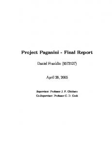
Droplet Microexplosion and Cenosphere Formation The discussion in the previous section suggests that under all combustion conditions, whether heat transfer to the fuel spray droplets is dominated by conduction from the ambient gases or by local feedback from a droplet flame, pyrolysis oils burn much slower than conventional fuel oils. The primary causes of this, the high mass density and the high latent heat of vaporization of pyrolysis oils, are not likely to be modified significantly without extensive oil dilution with a light additive. Therefore, in order to assure carbon burnout and proper flame shape and length in existing burners, either the droplet sizes must be made smaller with the pyrolysis oils (a difficult challenge, given the poor atomization properties of these oils) or the larger spray droplets must undergo microexplosions. In order to evaluate the relevant factors governing the timing and intensity of microexplosions, a brief review of the current understanding of droplet microexplosion phenomena is required. Microexplosions occur in multicomponent droplets with a suitably broad range of volatilities. The driving force for microexplosions is the much faster process of thermal transport (diffusion) within liquids compared to mass transport. This ratio is characterized by the liquid Lewis number, which typically has a value from 10–30. The effect of these unbalanced transport processes is demonstrated schematically in Fig. 14, wherein idealized profiles of the surface and center temperature and volatile concentration are shown as a function of droplet mass loss. Since the droplet surface temperature is at the boiling point of the instantaneous molecular mixture at the surface, it increases rapidly as the more volatile components become relatively depleted from a layer near the droplet surface. The temperature rise at the droplet surface is followed by a rise at the center of the droplet, as thermal energy is rapidly diffused into the droplet interior. In a particle-free liquid, a microexplosion occurs when a characteristic temperature (the superheat limit) is reached by the liquid mixture at some location within the droplet. This homogeneous superheat limit has been shown to be approximately equal to 0.9 times the thermodynamically defined critical temperature for a wide range of substances at 1 atm pressure (Blander and Katz, 1975; Avedisian, 1985). At higher pressures, the superheat limit rises slowly, showing a linear variation with pressure such that the superheat limit equals the critical temperature at the critical pressure (Avedisian, 1985). For liquid mixtures, the superheat limit is roughly a weighted linear function of the mole fractions of the components. For a particle-laden liquid, the superheat limit is reduced below the homogeneous superheat limit, due to the lower energy required for heterogeneous bubble nucleation (Blander and Katz, 1975).
42
Mole Fraction of Volatile Components
700
Temperature (K)
600 surface center
500
400
300 0.0
0.2
0.4
0.6
0.8 3
0.4
center
0.3 surface 0.2
0.1
0.0 0.0
1.0
0.2
0.4
0.6
0.8 3
3
1.0 3
Non-Dimensional Mass Loss, M ( = 1 - r / r0 )
Non-Dimensional Mass Loss, M ( = 1 - r / r0 )
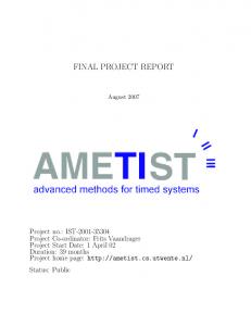
Figure 14. Schematic representations of (a) the temperature, and (b) the molar concentration of more volatile components, as a function of the droplet mass loss during combustion of a multicomponent droplet with a wide range of volatilities. These figures are derived from Law (1989) for a liquid Lewis number of 30, modifying the temperature range and variation to reflect a typical volatility range for pyrolysis oils. The critical questions to be answered of relevance to practical applications are the following: (a) at what point during a droplet’s lifetime is a microexplosion likely to occur (if ever), and (b) how effective will that microexplosion be in breaking up the initial droplet mass. Unfortunately, modeling the droplet combustion behavior of multicomponent fuels is very complex, even when only considering a bicomponent mixture of compounds with well-known transport properties (Megaridis and Sirignano, 1990). For pyrolysis oils, which contain a wide variety of complex chemical compounds, many of whose transport properties are unknown, realistic modeling would be very difficult. Further compounding the situation are liquid-phase chemical reactions that are thought to be occurring during combustion of pyrolysis oils and the need to estimate the relevant transport properties and evaporation behavior of the actual chemical mixtures. Also, detailed computations of microexplosion occurrence have not yet been attempted, although it is seemingly feasible, particularly for bicomponent mixtures. Therefore, one has to rely on qualitative scaling arguments to predict the microexplosion behavior of pyrolysis oils in practical combustors. The general nature of the multicomponent droplet vaporization or combustion process (i.e., whether it is more of a batch-distillation process or a diffusion-limited process) is controlled by two non-dimensional numbers, the liquid Lewis number (Lel = αl/Dl) and the liquid Peclet number (Pel = K(t)/Dl), where αl and Dl are the liquid thermal diffusivity and liquid mass diffusivity, respectively (Makino and Law, 1988). K(t) refers to the instantaneous droplet evaporation or combustion rate. As noted before, the liquid Lewis number is a characteristic property of the liquid fuel (at a given pressure and temperature) and is typically quite large. The value of the Peclet number, on the other hand, is dependent on the rate of droplet vaporization, and therefore is dependent on the conditions under which the droplets are being evaporated or combusted. For example, for pyrolysis oil droplets in a 1500 K environment, Table 4 shows that Kc/Kv ≈ 2. Therefore, for pyrolysis oil droplets evaporating at 1500 K without a surrounding flame, the Peclet number is reduced two-fold from droplet combustion in a 1500 K oxidizing environment (with 24 mole-% O2). For microexplosions to occur, both Lel and Pel must be large, to assure that the transport of heat within the droplets is much faster than molecular transport and to assure that the 43
droplet evaporation rate is large enough that molecular transport can’t keep up. Note that neither the Lel or Pel are expected to be dependent on droplet size. Therefore, although most practical pyrolysis oil combustors produce sprays with smaller drop sizes than those investigated in this droplet study, the same tendency for droplet microexplosion should exist for these smaller droplets, assuming they experience a similar hot, oxidizing environment. Indeed, in recent years a number of diagnostic studies of spray flames have discovered evidence of droplet microexplosion behavior when burning fuels that demonstrate microexplosions during droplet combustion. For example, Mattiello et al. (1992) used laser light scattering and cascade impactor sampling measurements to demonstrate the localized, rapid destruction of the larger drops in a fuel oil-water emulsion spray flame, in comparison to a oil-only flame. In addition, Presser et al. (1994) used phase Doppler interferometry to demonstrate microexplosions occur in spray flames of methanol/dodecanol mixtures. The effect of elevated pressures, such as are present in diesel engines and gas turbine combustors, on the microexplosion process and burnout of pyrolysis oils is a complex subject. In general, higher pressures tend to promote microexplosions in burning, multicomponent droplets, due to the relative insensitivity of the superheat limit with pressure, in comparison with the significant changes in liquid boiling points (Lasheras et al., 1984; Wang and Law, 1985). This is illustrated in Figure 15, where the pressure dependence of the boiling points of some pyrolysis oil components are shown, together with the superheat limits of water (the dominant volatile component of pyrolysis oils) and methanol (a suggested additive). The higher liquid boiling points increase the droplet surface temperature during combustion and consequently increase the heating rate of the droplet interior. In fact, depending on the details of the thermal and molecular transport in the droplets, it is possible that the tendency for microexplosion may initially increase with rising pressure, but then decrease at even higher pressures (Niioka and Sato, 1986). Of course, at the critical point of the droplet, the whole concept of microexplosion becomes moot. The effect of elevated pressure on the effectiveness of droplet microexplosions is also complex. At first glance, the forcefulness of the microexplosion would be expected to drop monotonically with increasing pressure, due to a reduction in the vapor bubble expansion driving force, the difference between the saturation pressure of the vapor at its superheat limit and the ambient pressure. However, complicating factors in this analysis are the pressure and temperature dependencies of the liquid diffusivity, viscosity, and surface tension. In addition, for pyrolysis oils the Arrhenius nature of the viscosity- and water-increasing chemical reactions during combustion of the oil must be considered. Overall, though, the expectation is that the effectiveness of microexplosions in dispersing the initial droplet mass will decrease with increasing pressure.
44
600
(a)
phenanthrene
500
Boiling Point (°C)
400
naphthalene phenol
300 water 200 methanol
100
0 0
5
10
15
20
15
20
Pressure (atm) 600
(b)
Superheat Limit (°C)
500
400 water 300 methanol 200
100
0 0
5
10 Pressure (atm)
Figure 15. Plots demonstrating (a) the increase in boiling point of some representative components of pyrolysis oils as a function of ambient pressure (data from Reid et al., 1987), in contrast to (b) the relative insensitivity of the superheat limit (of the more volatile compounds) (data from Avedisian, 1985).
45
Conclusions Under the auspices of the Biomass Power Program and the National Renewable Energy Laboratory, the U.S. Department of Energy supported work at Sandia, from 1992 to 1997, to investigate the combustion properties of biomass flash pyrolysis oils. This final project report summarizes the chemical and physical properties of pyrolysis oils, the results of other investigations (within the U.S., Canada, and Western Europe) into the combustion of pyrolysis oils, the results of Sandia’s experiments on the combustion behavior of pyrolysis oils, and the application of laboratory droplet combustion analysis to predicitions of performance in practical combustors. Pyrolysis oils clearly have some detrimental physical and chemical properites in comparison to conventional fossil-based liquid fuels, particularly their acidity, low energy value, high char content and viscosity, and instability. Work at NREL demonstrated that some of these properties could be dramatically improved with the implementation of advanced hot-gas filtration techniques during pyrolysis oil production, but acidity and low energy value are inherent properties of the molecular constitution of the pyrolysis oils. The use of inexpensive chemical additives has shown promise in reducing viscosity and increasing oil stability, and may also help neutralize the pyrolysis oils. Worldwide, limited combustion testing has been performed with pyrolysis oils in furnaces and boilers, diesel engines, and gas turbine combustors. These investigations have shown that pyrolysis oils have poor ignition quality and that firing pyrolysis oils generally results in high emissions of particulates and CO. Surprisingly, in spite of their ignition difficulties and the high water content of the pyrolysis oils, their overall burning rates in these combustors appear to be similar to that of conventional fuel oils. Measurements at Sandia, supported by theoretical analysis, show that the droplet evaporation and combustion rates of pyrolysis oils are substantially lower (by a factor of 2–3) than that of a light fuel oil. However, due to the wide range of volatilities of the constituents of pyrolysis oils, pyrolysis oil droplets experience microexplosions that disperse the original droplet mass into a number of droplet fragments. The timing and effectiveness of droplet microexplosions in rapidly dispersing the fuel mass is dependent on the severity of the oil-producing pyrolysis process, the water content of the pyrolysis oil, and the amount of char suspended in the oil. The occurrence and effectiveness of microexplosions in practical combustion systems is important both to assure reasonably fast combustion rates of the pyrolysis oils and to limit the emission of CO and coke-derived particulate. Droplet combustion theory predicts that microexplosions will continue to play an important role in most practical applications of pyrolysis oils. As enumerated in the attached supplement, provided by Finland’s Steven Gust, with the current status of petroleum-fuel taxes and renewable energy incentives in place in Europe, production and combustion of biomass pyrolysis oils for power and steam production is nearly economically feasible for some countries. In the U.S., pyrolysis oils are clearly not an economic alternative for power production at this time, except perhaps for application to a few remote, wooded locations where the price of delivered diesel fuel is extremely high and biomass feedstocks are readily available. In the future, rising petroleum costs and increased incentives for the use of indigenous, renewable resources may make pyrolysis oils a broadly applicable source of liquid fuels in the U.S. Irrespective of the economics, biomass oils currently have significant storage, handling, and combustion difficulties that limit their application. One possible method by which these shortcomings may be circumvented is to use mixtures of pyrolysis oils with other fuels, analogous to the present thrust on the cofiring of solid biomass feedstocks with coal in utility boilers.
46
Because bio-oils have poor miscibility with light petroleum fuel oils, the most suitable cofiring fuels for the bio-oils would be methanol or ethanol.
Acknowledgments Judy Wornat, now on the faculty of the Mechanical and Aerospace Department of Princeton University, and Kevin Davis, now at Reaction Engineering International, in Salt Lake City, served as primary investigators of this project for the first two years of this project. Brad Porter assisted with data collection for the pine and oak oils. Sid Huey was primarily responsible for data collection for the NREL switchgrass and poplar oils and diesel fuel and for maintaining the entrained flow reactor system. Jeff Davis, a Cornell University coop student, assisted in the examination of poplar oils 160 and 174. Paul Tennison, now at the University of Wisconsin, performed the experiments for the Ensyn oil, No. 6 fuel oil, and the oil/water/methanol mixture investigation. Dana Adams, a Cornell University coop student, analyzed the droplet images from the mixture investigation and No. 6 fuel oil experiments. Tom Milne, Jim Diebold, and John Scahill of NREL are thanked for supplying the NREL biomass oils and their characterization data, as well as information about the pyrolysis reactor conditions during their production. Don Huffman of Ensyn graciously provided a sample of Ensyn oak oil and its chemical analysis. Scott Drennan and Steve Londerville of The Coen Company are thanked for their advice and perspective as a commercial burner manufacturer. The U.S. DOE’s Biomass Power Program and the National Renewable Energy Laboratory provided the financial support to conduct this project.
47
List of References Agblevor, F.A., and Besler, S. (1996) “Inorganic compounds in biomass feedstocks. 1. Effect on the quality of fast pyrolysis oils”, Energy & Fuels 10:293–298. Andrews, R.G., Zukowski, S., and Patnaik, P.C. (1997) “Feasibility of firing an industrial gas turbine using a bio-mass derived fuel”, Developments in Thermochemical Biomass Conversion (A.V. Bridgwater and D.G.B. Boocock, Eds.), Blackie Academic and Professional, London, pp. 495–506. Annual Energy Review 1997, Energy Information Administration, U.S. Department of Energy, Washington DC, DOE/EIA-0384(97), July 1998. Ardy, P.L., Barbucci, P., Benelli, G., Rossi, C., and Zanforlin, S. (1995) “Development of gas turbine combustor fed with bio-fuel oil”, Proceedings: Second Biomass Conference of the Americas, NREL, Golden CO 80401, CP-200-8098, pp. 429–438. ASTM D 396-92, Annual Book of ASTM Standards, Vol. 05.01, 1992. Avedisian, C.T. (1985) “The homogeneous nucleation limits of liquids”, J. Phys. Chem. Ref. Data 14:695–729. Bakhshi, N.N., personal communication, 1997. Bakhshi, N.N., and Adjaye, J.D. (1995) “Characteristics of a fast pyrolysis bio-fuel and its miscibility with oxygenated and conventional fuels”, Proceedings: Second Biomass Conference of the Americas, NREL, Golden CO 80401, CP-200-8098, pp. 1079–1088. Barbucci, P. Costanzi, F., Ligasacchi, S., Mosti, A., and Rossi, C. (1995) “Bio-fuel oil combustion in a 0.5 MW furnace”, Proceedings: Second Biomass Conference of the Americas, NREL, Golden CO 80401, CP-200-8098, pp. 1110–1120. Baxter, L.L. (1993) “Ash deposition during biomass and coal combustion: a mechanistic approach”, Biomass and Bioenergy 4:85–102. Blander, M., and Katz, J.L. (1975) “Bubble nucleation in liquids”, AIChE Journal 21:833–848. Bridgwater, A.V., and Cottam, M.-L. (1992) “Opportunities for biomass pyrolysis production and upgrading”, Energy & Fuels 6:113–120. Chen, G., and Gomez, A. (1997) “Dilute laminar spray diffusion flames near the transition from group combustion to individual droplet burning”, Comb. and Flame 110:392–404. Conti, L., Scano, G., Boufala, J., and Mascia, S. (1997) “Bio-crude oil hydrotrating in a continuous bench-scale plant”, Developments in Thermochemical Biomass Conversion (A.V. Bridgwater and D.G.B. Boocock, Eds.), Blackie Academic and Professional, London, pp. 622–632.
48
Czernik, S., Johnson, D.K., and Black, S. (1994) “Stability of wood fast pyrolysis oil”, Biomass and Bioenergy 7:187–192. Czernik, S., Scahill, J., and Diebold, J. (1995) “The production of liquid fuel by fast pyrolysis of biomass”, ASME J. Solar Energy Engin. 117:2–6. D’Alessio, J., Lazzaro, M., Massoli, P., and Moccia, V. “Thermo-optical investigation of burning biomass pyrolysis oil droplets”, Twenty-Seventh International Symposium on Combustion, The Combustion Institute, Pittsburgh, PA, 1998, in press. Diebold, J.P., personal communication, 1995. Diebold, J., and Czernik, S. (1997) “Additives to lower and stabilize the viscosity of pyrolysis oils during storage”, Energy & Fuels 11:1081–1091. Diebold, J.P., and Scahill, J.W., “Improvements in the vortex reactor design”, Developments in Thermochemical Biomass Conversion (A.V. Bridgwater and D.G.B. Boocock, Eds.), Blackie Academic and Professional, London, 1997, pp. 242–252. Diebold, J.P., Czernik, S., Scahill, J.W., Phillips, S.D., and Feik, C.J. (1994) “Hot-gas filtration to remove char from pyrolysis vapors produced in the vortex reactor at NREL”, Proceedings: Specialists Workshop on Biomass Pyrolysis Oil Properties and Combustion, Estes Park CO, Sept. 26–28, NREL, Golden CO 80401, CP-430-7215, pp. 90–109. Diebold, J.P., Milne, T.A., Czernik, S., Oasmaa, A., Bridgwater, A.V., Cuevas, A., Gust, S., Huffman, D., and Piskorz, J., “Proposed specifications for various grades of pyrolysis oils”, Developments in Thermochemical Biomass Conversion (A.V. Bridgwater and D.G.B. Boocock, Eds.), Blackie Academic and Professional, London, 1997, pp. 433–447. Diebold, J.P., Scahill, J.W., Czernik, S., Phillips, S.D., and Feik, C.J. “Progress in the production of hot-gas filtered biocrude oil at NREL”, in Bio-Oil Production and Utilization. Proceedings of the Second EC/Canada Workshop on Thermal Biomass Processing (A.V. Bridgwater and E. Hogan, Eds.), CPL Scientific Information Services, Ltd., Newbury U.K., 1996, pp. 66–81. Elliott, D.C. (1994) “Water, alkali, and char in flash pyrolysis oils”, Biomass and Bioenergy 7:179–185. Elliott, D.C., and Neuenschwander, G.G., “Liquid fuels by low-severity hydrotreating of biocrude”, Developments in Thermochemical Biomass Conversion (A.V. Bridgwater and D.G.B. Boocock, Eds.), Blackie Academic and Professional, London,1997, pp. 611–621. Evans, R.J., and Milne, T.A. (1987a) “Molecular characterization of the pyrolysis of biomass. 1. Fundamentals” Energy & Fuels 1: 123–137.
49
Evans, R.J., and Milne, T.A. (1987b) “Molecular characterization of the pyrolysis of biomass. 2. Applications” Energy & Fuels 1: 311–319. French, R.J., and Milne, T.A. (1994) “Vapor phase release of alkali species in the combustion of biomass pyrolysis oils”, Biomass and Bioenergy 7:315–325. Godsave, G.A.E., “Studies of the combustion of drops in a fuel spray – the burning of single drops of fuel”, Fourth Symposium (International) on Combustion, The Combustion Institute, Pittsburgh PA, 1953, pp. 818–830. Graham, R.G., Freel, B.A., Huffman, D.R., and Bergougnou, M.A. (1994) “Commercial-scale rapid thermal processing of biomass”, Biomass and Bioenergy 7:251–258. Green, G.J., Takahashi, F., Walsh, D.E., and Dryer, F.L. (1989) “Aerodynamic device for generating mono-disperse fuel droplets”, Rev. Sci. Instrum. 60:646–652. Gust, S., “Combustion experiences of flash pyrolysis fuel in intermediate size boilers”, Developments in Thermochemical Biomass Conversion (A.V. Bridgwater and D.G.B. Boocock, Eds.), Blackie Academic and Professional, London,1997, pp. 481–488. Horne, P.A., and Williams, P.T. (1996) “Influence of temperature on the products from the flash pyrolysis of biomass”, Fuel 75:1051–1059. Huffman, Dave, personal communication, 1995. Kanury, A.M., Introduction to Combustion Phenomena, Gordon and Breach, New York, 1975. Lasheras, J.C., Yap, L.T., and Dryer, F.L. “Effect of the ambient pressure on the explosive burning of emulsified and multicomponent fuel droplets”, Twentieth Symposium (International) on Combustion, The Combustion Institute, Pittsburgh PA, 1984, pp. 1761–1772. Law, C.K. (1982) “Recent advances in droplet vaporization and combustion”, Prog. Energy Combust. Sci. 8:171–201. Law, C.K., lecture notes on Combustion Theory, 1989. Lazzaro, M., Massoli, P., Moccia, V., D’Alessio, J. “Lab scale study of wood pyrolysis oil droplets heated in a free falling drop tube furnace”, Proceedings of the 13th Annual Conference on Liquid Atomization and Spray Systems, Florence Italy, July 9–11, 1997. Lefebvre, A.H. (1985) “Fuel effects on gas turbine combustion – ignition, stability, and combustion efficiency”, J. Engring Gas Turb. and Power 107:24–37. Lefebvre, A.H. (1991) “Fuel atomization, droplet evaporation, and spray combustion”, in Fossil Fuel Combustion: A Source Book (W. Bartok and A.F. Sarofim, Eds.), John Wiley & Sons, New York, pp. 529–652.
50
Londerville, Steve, personal communication, 1995. Maggi, R., and Delmon, B. (1994) “Comparison between ‘slow’ and ‘flash’ pyrolysis oils from biomass”, Fuel 73:671–677. Maggi, R., and Elliott, D.C. (1997) “Upgrading overview”, Developments in Thermochemical Biomass Conversion (A.V. Bridgwater and D.G.B. Boocock, Eds.), Blackie Academic and Professional, London, pp. 575–588. Makino, A., and Law, C.K. (1988) “On the controlling parameter in the gasification behavior of multicomponent droplets”, Comb. and Flame 73:331–336. Mattiello, M., Cosmai, L., Pistone, L., Beretta, F., and Massoli, P. “Experimental evidence for microexplosions in water/fuel oil emulsion flames inferred by laser light scattering”, Twenty-Fourth Symposium (International) on Combustion, The Combustion Institute, Pittsburgh PA, 1992, pp. 1573–1578. Megaridis, C.M., and Sirignano, W.A. “Numerical modeling of a vaporizing multicomponent droplet”, Twenty-Third Symposium (International) on Combustion, The Combustion Institute, Pittsburgh PA, 1990, pp. 1413–1421. Megaridis, C.M., and Sirignano, W.A. (1992) “Multicomponent droplet vaporization in a laminar convective environment”, Combust. Sci. and Tech. 87:27–44. Meier, D., Oasmaa, A., and Peacocke, G.V.C. “Properties of fast pyrolysis liquids: status of test methods”. Developments in Thermochemical Biomass Conversion (A.V. Bridgwater and D.G.B. Boocock, Eds.), Blackie Academic & Professional, London, 1997, pp. 391408. Milne, T., Agblevor, F., Davis, M., Deutch, S., and Johnson, D. “A review of the chemical composition of fast-pyrolysis oils from biomass”, Developments in Thermochemical Biomass Conversion (A.V. Bridgwater and D.G.B. Boocock, Eds.), Blackie Academic & Professional, London, 1997, pp. 409-424. Moses, C.A., and Bernstein, H. (1994) Impact Study on the Use of Biomass-Derived Fuels in Gas Turbines for Power Generation, NREL, Golden CO 80401, TP-430-6085. Mulholland, J.A., Srivastava, R.K., Wendt, J.O.L., Agrawal, S.R., and Lanier, W.S. (1991) “Trajectory and incineration of rogue droplets in a turbulent diffusion flame”, Comb. and Flame 86:297–310. Niioka, T., and Sato, J. “Combustion and microexplosion behavior of miscible fuel droplets under high pressure”, Twenty-First Symposium (International) on Combustion, The Combustion Institute, Pittsburgh PA, 1986, pp. 625–631. Presser, C., Gupta, A.K., Avedisian, C.T., and Semerjian, H.G. (1994) “Effect of dodecanol content on the combustion of methanol spray flames”, Atomization and Sprays, 4:207–222.
51
Radlein, D., Piskorz, J, and Scott, D.S. (1987) “Lignin derived oils from the fast pyrolysis of poplar wood”, J. Anal. Appl. Pyrolysis 12:51–59. Reid, R.C., Prausnitz, J.M., and Poling, B.E., The Properties of Gases and Liquids (4th ed.) McGraw-Hill, New York, 1987. Scahill, J.W., personal communication, 1995. Scahill, J.W., Diebold, J.P., and Feik, C. “Removal of residual char fines from pyrolysis vapors by hot gas filtration”, Developments in Thermochemical Biomass Conversion (A.V. Bridgwater and D.G.B. Boocock, Eds.), Blackie Academic and Professional, London, 1997, pp. 253–266. Shaddix, C.R., and Huey, S.P. “Combustion characteristics of fast pyrolysis oils derived from hybrid poplar”, Developments in Thermochemical Biomass Conversion (A.V. Bridgwater and D.G.B. Boocock, Eds.), Blackie Academic and Professional, London, 1997, pp. 465–480. Shaddix, C.R., and Tennison, P.J. “Effects of Char Content and Simple Additives on Biomass Pyrolysis Oil Droplet Combustion”, 27th International Symposium on Combustion, in press. Shihadeh, A., Lewis, P., Manurung, R., and Beér, J. (1994) “Combustion characterization of wood-derived flash pyrolysis oils in industrial-scale turbulent diffusion flames”, Proceedings: Specialists Workshop on Biomass Pyrolysis Oil Properties and Combustion, Estes Park CO, Sept. 26–28, NREL, Golden CO 80401, CP-430-7215, pp. 281–295. Shihadeh, A.L. “Rural electrification from local resources: biomass pyrolysis oil combustion in a direct injection diesel engine”, D.Sc. thesis, Department of Mechanical Engineering, MIT, Sept. 1998. Sirignano, W.A. (1983) “Fuel droplet vaporization and spray combustion theory”, Prog. Energy Combust. Sci. 9:291–322. Solantausta, Y., Nylund, N.-O., and Gust, S. (1994) “Use of pyrolysis oil in a test diesel engine to study the feasibility of a diesel power plant concept”, Biomass and Bioenergy 7:297–306. Wang, C.H., and Law, C.K. (1985) “Microexplosion of fuel droplets under high pressure”, Comb. and Flame 59:53–62. Wang, X.F., and Lefebvre, A.H. (1988) “Influence of fuel temperature on atomization performance of pressure-swirl atomizers”, J. Propulsion 4:222–227. Wood, B.J., Wise, H., and Inami, S.H. (1960) “Heterogeneous combustion of multicomponent fuels”, Comb. and Flame 4:235–242.
52
Wornat, M.J., Porter, B.G., and Yang, N.Y.C. (1994) “Single droplet combustion of biomass pyrolysis oils”, Energy & Fuels 8:1131–1142.
53
Project Presentations and Publications Davis, K.A., Huey, S.P., and Davis, J.E., “Microexplosion Behavior of Biomass-Derived Pyrolysis Oils During Single Droplet Combustion”, Spring Meeting of the Central States/Western States/Mexican National Sections of the Combustion Institute, San Antonio TX, April 23–26, 1995. -- manuscript included in conference proceedings. Davis, K.A., Wornat, M.J., Hurt, R.H., and Frew, E., “Comparison of the Combustion Characteristics of Biomass and Coal Chars”, presented at the 1994 Annual AIChE Meeting, San Francisco CA, Dec 1994. Huey, S.P., Davis, K.A., Hurt, R.H., and Wornat, M.J., “Comparison of Biomass and Coal Char Reactivities”, presented at the 1995 National Meeting of the American Chemical Society, Fuel Chemistry Division, Chicago IL, Aug 21–22, 1995. -- published in Prepr. Div. Fuel Chem., Amer. Chem. Soc. 40(3):694–698, 1995. Shaddix, C.R., “Combustion Properties of Biomass Pyrolysis Oils”, presented at the 1997 Annual AIChE Meeting, Los Angeles CA, Dec 1997. Shaddix, C.R., and Huey, S.P., “Combustion Characteristics of Fast Pyrolysis Oils Derived from Hybrid Poplar”, presented at Developments in Thermochemical Biomass Conversion, Banff Canada, May 20–24, 1996. -- published in Developments in Thermochemical Biomass Conversion, (A.V. Bridgwater and D.G.B. Boocock, Eds.), Blackie Academic and Professional, London, 1997, pp. 465–480. Shaddix, C.R., and Tennison, P.J., “Effects of Char Content and Simple Additives on Biomass Pyrolysis Oil Droplet Combustion”, presented at the Twenty-Seventh Symposium (International) on Combustion, Boulder CO, July 31–Aug 5, 1998. -- published in Twenty-Seventh Symposium (International) on Combustion, The Combustion Institute, Pittsburgh PA, in press. Shaddix, C.R., Huey, S.P., Davis, and Wornat, M.J., “Fundamental Aspects of Combustion of Biomass Pyrolysis Oils”, presented at the Engineering Foundation conference on Biomass Usage for Utility and Industrial Power, Snowbird UT, April 28–May 3, 1996. -- manuscript included in conference proceedings. Shaddix, C.R., Huey, S.P., Davis, and Wornat, M.J., “Fundamental Aspects of Combustion of Biomass Pyrolysis Oils”, presented at the Western States Meeting of the Combustion Institute, Livermore CA, April 14–15, 1997. -- manuscript included in conference proceedings as paper no. WSS/CI 97S-073. Wornat, M.J., Hurt, R.H., Davis, K.A., and Yang, N.Y.C., “Single-Particle Combustion of Two Biomass Chars”, presented at the Twenty-Sixth Symposium (International) on Combustion, Naples Italy, Aug 1996.
54
-- published in Twenty-Sixth Symposium (International) on Combustion, The Combustion Institute, Pittsburgh PA, 1996, pp. 3075–3083. Wornat, M.J., Hurt, R.H., Yang, N.Y.C., and Headley, T.J., “Structural and Compositional Transformations of Biomass Chars During Combustion”, presented at the Twenty-Fifth Symposium (International) on Combustion, Irvine CA, July 31–August 5, 1994. -- published in Combustion and Flame 100:133–145, 1995. Wornat, M.J., Porter, B.G., and Yang, N.Y.C., “Single Droplet Combustion of Biomass Pyrolysis Oils”, Energy & Fuels 8:1131–1142, 1994. Wornat, M.J., Porter, B.G., Yang, N.Y.C., and Davis, K.A., “Single Droplet Combustion of Biomass Pyrolysis Oils”, presented at the Specialists Workshop on Biomass Pyrolysis Oil Properties and Combustion, Estes Park CO, Sept. 26–28, 1994.
55
Supplement: Combustion of Pyrolysis Oils in Europe by Steven Gust, Neste Oy, Finland
Driving Forces in Europe Pyrolysis liquid (i.e. oil) production and use as a fuel for power and heat applications is rapidly approaching market introduction and pre-commercialization in Europe. The reasons for this are listed below: 1. the desire to increase the percentage of indigenous energy 2. government policies that tend to impose high taxes on fossil fuels while providing biofuels with tax exemptions 3. the goal to reduce net emissions of fossil CO2 4. agricultural policy and the need to increase employment in rural areas 5. pan-European and national energy programs that assist in the development and introduction of new energy technologies. Taken together, these incentives will permit a number of large demonstration projects to be realized in Europe within the next couple of years. These demonstration projects will be part of the overall goal of increasing renewable energy use in Europe, as has been seen for photovoltaic, wind, and other biofuel programs such as use of vegetable oils and gasification. These incentives are accepted as necessary for early commercialization in order to reduce the risk to industry. A good example of this is the NFFO (non-fossil fuel obligation) program in the United Kingdom where industry bids for megawatts of electricity with pyrolysis, gasification, and combustion technologies competing. The main short-term challenge to these programs is the present low world price for petroleum products and the liberalization of energy markets in Europe, which is leading to lower energy prices in general.
Critical Issues for Applications With the scale-up of fast pyrolysis production to the tens-of-metric-tons per day level, large quantities of product are being made available for application testing. Applications include turbines, stationary diesels or boilers. On the boiler side, both small residential and large industrial boilers are considered. Initial testing has shown that pyrolysis liquids can be injected, ignited and combusted in existing equipment that has been modified to handle the special chemical and physical characteristics of pyrolysis liquids. Emissions can be reduced to acceptable levels except possibly for particulates without any special post-combustion gas treatment. It has been calculated that the cost to upgrade a pyrolysis liquid to a fully compatible petroleum product is prohibitive and thus currently the emphasis is on developing and modifying existing combustion systems to handle the special properties of pyrolysis liquids. Fuel quality is the critical issue and the main properties of interest are viscosity, concentration of char and ash, and fuel stability. While viscosity and contaminant levels can be adjusted and handled by modifying production conditions, fuel stability or reactivity is much more difficult to control with present
56
production processes. Stability of pyrolysis liquids includes tendency to phase-separate, to polymerise, to coke at high temperatures, to oxidize, and to form thick films.
Fuel Prices and Pyrolysis Use Pyrolysis liquids could replace either heavy or light fuel oils. These fuels are used for both heating and power applications. The general trend in most countries is to impose higher taxes on light fuel oils than for heavy fuel oils (Fig. S-1). In the figure, full taxes are shown, but in many countries industry is refunded part of the tax (VAT), so the actual cost to industry is lower. The fuel price includes the cost of raw material, refining and distribution, plus taxes. In 1998 there has been downward pressure on prices as crude oil prices have been under the 15 US$ per barrel range. Figure S-1. Bar chart of 1998 estimated production costs and imposed taxes for light fuel oil 0.8
tax cost
0.7 0.6
ECU/l
0.5 0.4 0.3 0.2 0.1 0 LFO USA
HFO
LFO Germany
HFO
LFO Italy
HFO
LFO Denmark
HFO
LFO Sweden
HFO
LFO Finland
HFO
(LFO) and heavy fuel oil (HFO) in the U.S. and several European countries. Costs are given in ECU (the predecessor of the euro) per liter. At present it is very difficult for pyrolysis liquids to compete in power applications where the alternative fuel is heavy fuel oil. This is because production costs for pyrolysis liquids have been estimated in a number of studies to be on the order of 0.23–0.3 ECU/loe where ECU is the European predecessor of the euro (equal to ≈ 1.1 US$ in 1998) and loe is liter-of-oil-equivalent. For this reason, the work at Neste has concentrated on developing combustion applications where light fuel oil is normally used. In heating applications, heavy fuel oils begin to be used when boiler size is larger than 1 MWth and yearly consumption is large. Light fuel oils are normally restricted to small boilers (< 1 MWth). Of the light fuel oil market, the combustion of pyrolysis liquids in small residential boilers (< 20 kWth) is not probable due to fuel quality concerns. On the other hand, our tests have shown that use in intermediate-size boilers, on the order of 100 kW to 1 MW (about 20-200 pyrolysis litres/hour input), is possible.
57
Resource Base The possible feedstocks for pyrolysis liquid production are forestry residues and wastes, sawmill wastes, crop residues and purpose grown crops. In Scandinavia, especially in Finland and Sweden, the forestry residue resource base is considered to be adequate for the production of pyrolysis liquids. In Europe, the main feedstocks will be crop and forestry residues.
Combustion Technology Pressure atomisation is used exclusively for light fuel oil combustion. Here a pump raises the pressure of oil to 8–10 bars, forcing the oil through a swirl nozzle to produce a fine spray of oil droplets ranging in sizes from 30 to 100 microns in diameter. A fan provides the needed air for combustion and the oil droplets are heated, ignited, evaporated and combusted. Light fuel oils are characterized by low viscosity (5–15 cSt at room temperature), low autoignition temperatures (210–240 oC) and low residue levels (< 0.01%). They are called distillate fuels, which means that they do not form coke or leave deposits when heated and evaporated. Heat radiating back to the nozzle after shut-off will evaporate fuel in the nozzle but this does not interfere with nozzle operation. The frequency of these on/off cycles will depend on boiler sizing and climatic conditions, but 1 to 2 cycles per hour is not uncommon. When adapting these systems for pyrolysis oil use, this cycling behaviour poses significant challenges to the system design. Since pyrolysis liquids contain from 20–25% water, they do not readily ignite, which means an auxiliary fuel and high temperatures in the boiler is needed. After shut-off this heat must not be allowed to radiate back to nozzles containing pyrolysis liquid, otherwise thickening and coking will occur.
Combustion System Modifications Our work at Neste Oy continues on the design, development and testing of a variety of combustion system components, using commercial parts wherever possible. A variety of different refractorylined combustion chambers have been tested. After some modifications were implemented, the minimum temperature before pyrolysis oil could be fired was reduced by 200 oC and the time to reach this temperature was reduced from 20 minutes to 1 minute. A commercial boiler and a dualnozzle burner were used. Burner control was modified so that two fuels could be combusted simultaneously or independently. A 1-kW fuel preheater was used to adjust temperatures in the range 60-90 oC. A variety of commercial nozzles were tested including Danfoss, Delavan and Monarch. A Suntec mechanical pressure regulator was used. Nozzles, valves and pressure regulators will require replacement with acid-resistant materials. The original oil pump was replaced with a progressive-cavity pump. Different pump materials have been tested.
Samples Tested A variety of samples were tested, including those produced in Spain, Italy, Finland, Canada and the United States from different feedstocks and under different process conditions. Viscosity of samples stored under inert conditions approximately doubled during the 1-year storage. Viscosity was adjusted to initial levels by addition of alcohols. Phase-separation problems were seen with some samples. The best results to date were with fresh samples produced by VTT Energy from pine sawdust.
58
Combustion Results and Comparison The basic procedure for testing was to warm-up the combustion chamber with mineral oil through nozzle 1 to a minimum of 600-800 oC, switch on the pyrolysis oil pump and preheater to raise the pyrolysis oil temperature to 80-90 oC, switch on the pyrolysis oil nozzle 2 and switch off nozzle 1, adjust air for oxygen level in flue gas 6-9%. On shut-down it was necessary to rinse all traces of pyrolysis liquid out of the nozzle to avoid blocking. The main results of the combustion tests and comparison to other fuels is shown in Table S-1 below. Studies into droplet size are shown in the table under Sauter mean diameter. Good correlation was seen with droplet size and Table S-1:
Flash Pyrolysis Liquid Properties and Emissions Compared to Alternative Fuels medium-light flash pyrolysis fuel oil liquid
wood chips
heavy fuel oil
Water content wt%
0.02
18...25
15...20
0.5
Heating value MJ/kg MJ/l
42.4 36.9
17.....15 21...18
16...12 8...6
41 39.4
9 4 2
900....150 150...20 24...6
600 180 50
90
60...100
80
-
0.7 É 0.01
< 0.05
< 0.010
0.1...0.01
2...4
0.03
0.15
0
0
1
0
0.03....0.1
0.1...0.2
0.3
30-40 10 bar, 20 oC
60-40 20 bar, 85 oC
Viscosity cSt
30 oC 50 oC 80 oC
Flash point oC Solids Ash wt% Sulfur wt% Nitrogen wt% Sauter diameter µm
Typical emissions CO (ppm) NOx (ppm) particulates (Bach.) mg/Nm3 Pour point oC
30-50 120-150 2-5 50 - 150
15-30 80-120 0.2-1 15
-27
59
50-70 30 bar, 130 oC 500-6000 80-160 +tars, PAH
5-30 200-400 1-4 100-300 0
viscosity which indicates that to achieve good atomization and combustion, a viscosity of 10-15 cSt at the atomization temperature is desired.
Diesel Experiences In Europe, a number of companies and research institutes have carried out preliminary testing with pyrolysis liquids in diesel engines. These are VTT and Wärtsilä of Finland, Omrod of the UK and Pisa University of Italy. Engine performance and emissions have been measured. Emission monitoring includes CO, HC, NOx and particulates/soot. Wear of the injection pump and nozzles, deposits in the cylinder and valves were followed. Nozzle spray was studied in a manual test rig in order to control a stable spraying. Preliminary engine tests have been carried out earlier at VTT with a 60-kW Valmet engine and with a single-cylinder Petter AVB test engine, which is equipped with pilot injection. Fuel pump, pressure valve, and nozzle wear was so rapid that the test period was typically from one to five hours. Special materials, or a considerably improved oil quality, is required before additional tests are useful. Additional experiences are also needed for designing storage and fuel feeding equipment. Omrod is developing a diesel engine, which could be fired with BFO. Pilot injection is employed. Initial design work and operation has been carried out in 1996. The test engine is a medium-speed (750 rpm) 6-cylinder 250-kW Mirrlees-Blackstone diesel engine with pilot injection equipment. Typical pilot fuel amount is 5-10 % of total fuel energy. Wärtsila NSD has performed some single-cylinder tests using pyrolysis liquid but later decided to postpone further engine development until industrial-scale pyrolysis oil production for boiler applications is underway and fuel quality and specification is standardized. The conclusions from the diesel tests to date are: 1. pyrolysis liquid requires a pilot fuel for injection 2. major problems with corrosion were encountered when using conventional materials 3. due to low lower heating values for pyrolysis liquid, twice as much fuel must be injected in order to avoid derating; this is not possible with some engine designs 4. deposits are found in the injection system unless pyrolysis liquid is rinsed out after each use
Pyrolysis Quality Improvements In order for pyrolysis liquid to replace mineral oils, a number of basic fuel properties must be improved including viscosity, solids content, and stability. Other properties such as heating value, acidity, flash point, Conradson carbon etc. are considered to be fundamental properties of pyrolysis liquid and could only be improved with severe catalytic upgrading, which has been shown would significantly increase final product costs and limit market potential.
60
Therefore, the current strategy is to improve fuel properties by removal of solids by filtration, reduce viscosity by component addition and improve stability through use of components or additives. When these measures have been introduced it has been found that viscosity can be lowered to levels approaching light fuel oils and stability improved by a factor of 2–3. But to date these measures have taken place on a limited scale and it awaits to be seen if they can be implemented commercially.
Conclusions 1. Flash pyrolysis liquid can be combusted in boilers, diesel and gas engines and emissions reduced to acceptable levels with proper optimisation of combustion conditions. Due to high water content and low heating value of the fuel, ignition and flame stabilization must be assisted by either a pilot fuel or refractory-lined sections. 2. The combination of high temperatures required for pyrolysis liquid ignition and the thermally instability of the product requires special attention be paid to combustion chamber temperature profiles, especially close to fuel nozzles. 3. Due to problems encountered with storing, pumping, igniting, and keeping nozzles operable after shutdown, it is not likely that present quality levels of flash pyrolysis liquid would meet the requirements of a light fuel oil replacement. 4. Improvements to fuel quality by solids removal and component addition could enable pyrolysis liquid to be introduced into the market in large engines and boilers, provided that remaining questions concerning quality variation can be answered.
61