Jun 28, 2007 - drea Di Blas, David Dahle, Kevin Delaney, Brian Feaster, Leslie Grate, ... drew Hill, Jennifer Leech, Gabriel Littman, Daniel Littrell, Francisco J.
Finding the next computational model: Experience with the UCSC Kestrel Richard Hughey Andrea Di Blas Department of Computer Engineering University of California, Santa Cruz, CA 95064 rph, andrea @soe.ucsc.edu To appear in Journal of VLSI Signal Processing Systems, 2007. The original publication is available at www.springerlink.com �
June 28, 2007 Abstract Architects and industry have been searching for the next durable computational model, the next step beyond the standard CPU. Graphics co-processors, though ubiquitous and powerful, can only be effectively used on a limited range of stream-based applications. The UCSC Kestrel parallel processor is part of a continuum of parallel processing architectures, stretching from the application-specific through the application-specialized to the application-unspecific. Kestrel combines an ALU, multiplier, and local memory, with Systolic Shared Registers for seamless merging of communication and computation, and an innovative condition stack for rapid conditionals. The result has been a readily programmable and efficient co-processor for a wide range of applications, including biological sequence analysis, image processing, and irregular problems. Experience with Kestrel indicates that programmable systolic processing, and its natural combination with the Single Instruction-Multiple Data (SIMD) parallel architecture, is the most powerful, flexible, and power-efficient computational model available for large group of applications. Unlike other approaches that try to displace or replace the standard serial processor, our model recognizes that the expansion in the application landscape and performance requirements simply imply that the most efficient solution is the combination of more than one type of processor. We propose a model in which the CPU and the GPU are complemented by “the third big chip”, a massively-parallel SIMD processor.
1 Introduction Array processors and specialized hardware have long been used to accelerate some of the most computationally demanding algorithms and applications. As the march of technology improves performance and cost, these specialized processors may become ubiquitous in computing systems. Floating-point chips made this transition into the central processing unit (CPU) some time ago, and
graphics processing units (GPUs) are working toward this status. Massively-parallel SIMD array processors are a candidate for a similar transition, in support of another wide range of algorithms and applications. In this paper, we discuss the foundations and architecture of the University of California Santa Cruz (UCSC) Kestrel parallel processor. While the system has proved to be an applicationunspecific parallel processor, its design and philosophy is rooted in the domain of biological sequence analysis. Biological sequence analysis has long been a standard problem for application-specific processing and all other forms of high-performance computing. The underlying algorithms are simple and regular, and the amount of data for analysis is prodigious. University and commercial projects have tackled this problem since the early days of VLSI, and many of these approaches are chronicled within the proceedings of Application-Specific Arrays, Processors and Systems (ASAP) conference and its predecessors. The first such machine was Lopresti’s 1986 Princeton Nucleic Acid Comparator (P-NAC) [27, 28], a single-purpose systolic array that provided great speedup on its algorithm, and set the stage for the many application-specific VLSI and FPGA machines that followed. The second wave included the use of single-chip (MICSMACS) or single-board (Warp) processors to create short systolic arrays designed for signal processing but suitable for sequence analysis and other applications [11, 2]. This period also introduced three more specialized machines with moderate to extreme numbers of processing elements (PEs) on each chip. BISP (16 PEs/chip) and BioSCAN (892 PEs/chip) were application-specific, each suited to one specific algorithm [4, 36]. This wave also saw the development of P-NAC’s successor, the Brown Systolic Array (B-SYS, 47 PEs/chip). B-SYS incorporated full programmability as an application specialized processor, while maintaining a simple processing element design [19, 20, 15]. Flexibility and performance continued to increase with new machines from research projects and industry. The introduction of FPGA-based computing [43, 12] led to their use as sequence analysis engines [12, 5, 42, 24]. More general custom VLSI solutions also appeared [41], and the MasPar mini-supercomputer [31] became a common tool for bioinformatics research. The UCSC Kestrel architecture sought to build upon these designs while also preserving the B-SYS system’s simple and efficient SIMD programming model and high computational density. The result was a movement from the application-specialized B-SYS machine to the application-unspecific Kestrel machine, able to solve a far broader selection of problems than biological sequence analysis [16, 17, 14, 33, 8, 7]. The following sections describe the architectural and programming features that lead to Kestrel’s efficiency, moving from biological sequence analysis, to B-SYS, and then to Kestrel. Many of the features that made Kestrel successful reflect the values of good design: simplicity, regularity, and attention to detail. We conclude with an evaluation of the place of application-unspecific SIMD processing within the context of FPGA-based computation, multi-cores, graphics cards, and application-specific processing.
2
−
A B
C
−
A B
C
−
0
1
2
3
−
0
1
2
3
A
1
0
1
2
A
1
0
1
2
D
2
1
2
D
2
1
2
3
C
3
2
C
3
2
3
2
B
4
B
4
3
4
3
(a)
(b)
AB − C − A − DCB A− BC − AD − C B ABC − ADC B (c)
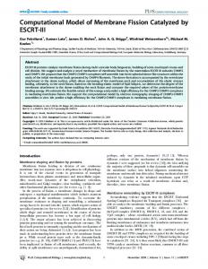
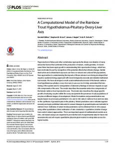
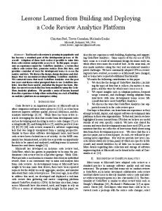
Figure 1: Dynamic programming sequence comparison, including (a) filling in the matrix and storing choices, (b) the complete matrix and best paths, and (c) the three optimal alignments.
2 Biological Sequence Analysis A core problem of bioinformatics is determining the relationship between molecules such as DNA, RNA, and proteins. Ideally, the biologist wishes to discover the physical relationship between the molecules (do they fold up the same way? are important residues conserved?), but often must rely on just the information relationship. One of the best ways to discover the information relationship between two sequences and is by using one of a family of related dynamic programming algorithms for pairwise sequence comparison. For two sequences, the correspondence is determined with a three-state model. The cost of aligning to is calculated by taking the minimum of three alternatives: (1) the two characters correspond to each other, in which case a match cost is added to ; (2) the character is not present in , in which case a deletion cost is added to ; or (3) the character is not present in , in which case an insertion cost is added :
��������� ��
��� ������� � �
��
��������� � � � �� ����� �� � � � ��� � � ��� � � � � � � ����� ��� � ����� � � � #$ ����� � �'��� �)( ��*,+�-/. match/mutate � �10����/2 % 2 ����� ��� �!�" $& ����������'��� � �'�� (( ����*,*,+�+�-/-/.. delete insert 2 � The complete algorithm consists of calculating all of the ����� � values in a two-dimensional dynamic programming matrix starting from �/34� 3 and working toward � � � (Figure 1a, with an insert or ����� �
delete cost of 1, match cost of 0, and mutate cost of 2). Each element is calculated based on three adjacent cells, leading to the three data dependencies. If an alignment is being created, an indicator of at least one of the minimizing choices should be saved (the lines in Figure 1a). The elements along any diagonal, such as the last finished one in Figure 1a may be calculated in parallel, since the data dependencies are only on values in the previous two diagonals. Once the calculation is complete, the minimizing choices leading back from the final score indicate an optimal alignment (the lines in Figure 1b). In this example, there are three optimal alignments, all with a cost of 3 according to this distance measure. The top alignment in Figure 1c has a deletion, insertion, and insertion; the middle has an insertion, deletion, and insertion; and the bottom has a mutation and insertion.
� ��
3
C
GG
A
rat
C _
. .
A
ecoli
. .
A
cow
A
U
. .
A
corn
Delete
Delete
A A A
Delete
A .95
A .03
A .95
C .02
C .63
C .02
G .02
G .01
G .02
U .01
U .33
U .01
Match
A .25 C .25 G .25 U .25
Match
A C G U
Insert
END
Match
.24 .24 .28 .24
Insert
A .25 C .25 G .25 U .25 Insert
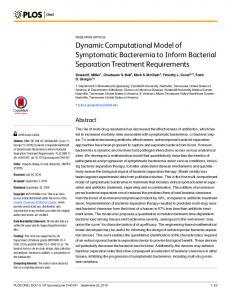
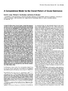
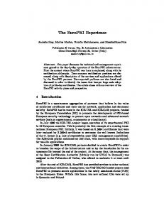
Figure 2: Hidden Markov model and corresponding alignment of three sequences. In practice, biologists use a more complicated form called the Smith-Waterman algorithm [30, 37], which involves three interleaved recurrence equations as well as gap initiation and continuation costs. The costs are centered around zero, in the example below with negative numbers showing probable correspondence. By thresholding the calculation with 0, and finding the best (most negative) score in the dynamic programming matrix, the highest scoring subsequencesubsequence region between the two sequences may be found:
� � �!�" 0 � " . � 0 � 0�� 2 ( � � �!�" � ( � 0�� ( � � �!�" � ( � 0�� ( � ���
���� �
�
�� ����
�
��� � �
��
�� ��
���
�� ��
����
��
��
����
�� �
�� � ���
�� �
��� � �� �
��� � �� � �� �
cost
. � � 0�����2
��
For the most exacting searches, bioinformatics practitioners use profile hidden Markov models (HMMs) [25, 9], which enable comparison and alignment of a single sequence to a family of sequences. HMMs also use three interleaved recurrences, but with higher precision and more complicated arithmetic.
� � �!�" � � � �!�" � � � �!�" � �
���� �
�� ����
���� � �
�
���
�� � �
( � � ( � � ( � � ( � � ( � � ( � �
�� ���
�� ��
���
���� �� �
��
��
�� �
����
����
����
�� �� ��
����
�� �
������� �
��
��� �
��
�����
( � ( ( � ( ( � (
�� ���
�� ��
� �� � �
���
�� � ��� � ��
��
��
��� � �
����� �
. � � 0�����2�0 cost . � � 0 �2�0 cost . 0�����2 � cost
�!
"!
A profile HMM (Figure 2) can be thought of as a generative model for a family of aligned sequences. Each state of the HMM corresponds to a column of the alignment, and contains a probability distribution over the amino acids or nucleotides. These probabilities, as well as those for 4
Time=0 Time=1 Time=2 Time=3 Time=4
0,0 1,0 2,0 3,0 4,0
0,1 1,1 2,1 3,1
0,2 1,2 2,2
0,3 1,3
−
A
B
C
B
C
D
A
4,1
3,2 4,2
2,3 3,3 4,3
Time=5 Time=6 Time=7
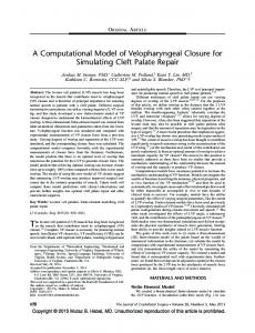
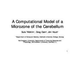
Figure 3: Index points calculated at each time step of the parallel dynamic programming algorithm. The example array, with one fixed sequence and one moving sequence, is shown at time step 4. insertions and deletions, can be trained from a set of sequences in an iterative process that includes repeatedly evaluating the HMM version of the dynamic programming calculation. In the dynamic programming calculation, the HMM replaces one of the sequences so that, for example, each column of the dynamic programming matrix corresponds to one state in the profile HMM. An alternate version of this algorithm, the forward algorithm, sums and multiplies probabilities, rather than maximizing and adding scores. This algorithm produces significantly better results for sequence alignment, discrimination, and HMM training [25]. These ���� algorithms have many mappings to linear arrays. For programmable machines, one of the best mappings is to preload one sequence (or the HMM) into the array, and then move the second sequence (or database) through the array from left to right. The dynamic programming matrix is thus calculated along diagonals, with calculated at step � �� in PE using values just calculated in PE and the adjacent PE (Figure 3). Because of the vast size of genomic and protein databases, many universities and companies have worked to accelerate the sequence comparison algorithms [16]. P-NAC, the first applicationspecific solution, placed 30 PEs on a chip, and implemented the above equation over a fourcharacter (DNA or RNA) alphabet, with an insert or delete cost of 1 [27, 28]. This simplicity enabled fast dynamic programming, critical for analyzing large sequence databases, but the lack of support for Smith-Waterman and other algorithms reduced the utility for biologists.
. �2
�
��� �
�/��� �
(
�
3 The Brown Systolic Array The goal of the Brown Systolic Array (B-SYS) was to develop a successor co-processor to PNAC. Maintaining simplicity similar to that of P-NAC was critical to ensure that many PEs could be placed on a single die, enabling large arrays to be created with only a handful of chips. It was also important to introduce programmability into the system. The family of sequence comparison algorithms is broad, and all or most of the many variations can only be accelerated on a programmable machine.
5
ALU Memory
result
left registers
left registers
ALU Memory
right registers
operands
right registers
left registers
right registers
operands
result
PE
PE
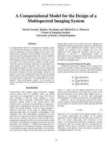
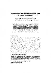
Figure 4: Systolic Shared Registers
WEST
EAST
REGISTER
REGISTER
F
BANK
A
(16 x 8)
B ALU R Z
C
L
BANK
A
(16 x 8)
G S
Ck
Ck
Ck
Ck
Figure 5: The B-SYS ALU with two flanking Systolic Shared Registers
Figure 6: The B-SYS chip with 47 processing elements.
6
// // // // // // //
The first opcode (e.g., xorABC) determines the result (stored in LF) based on two inputs (L2, R2) and the carry. The second opcode (e.g., Zsub) determines the operation of the carry chain, as well as the input and output flag registers. F7 is preset to 0, and F6 is preset to 1. The next iteration of this loop begins by comparing previous costs stored in L4 and R4, placing the result in R2 rather than R4.
// Compare two previous costs (L2, R2) xorABC L2 R2 LF Zsub F7 F1 // But do the comparison mod 256 fnA LF LF LF Zmsb F1 F1 // Select the minimum, place in LF selectABonC L2 R2 LF Zconst F1 F1 // Add 1, the insertion or deletion cost, to LF xorAC LF LF LF Zadda F6 F1 // Compare the characters in L1 and R0, passing the L1 // character to the right, feeding a character to the array fnA L1 R0 R1 matchAB F7 F2 load(*s++) // If the characters matched, use L4 as the cost, // otherwise use LF. Store result in R4 selectABonC L4 LF R4 Zconst F2 F2
Figure 7: B-SYS code for calculating edit distance mod-256 (as implemented in hardware by P-NAC). The natural choice for B-SYS was a linear systolic array, the most efficient architecture for sequence analysis. The linear array can be placed in low pin-count packages and is tremendously scalable. Of course, the cost of that scalability is ever increasing latencies from one end of the array to the other. As the Kestrel project was to demonstrate, the linear array is far more flexible as a computation engine than might be generally thought. B-SYS introduced the concept of Systolic Shared Registers (SSRs, Figure 4), in which register banks are shared between adjacent PEs. The SSRs enable seamless integration of computation and communication, as a single instruction can specify that values should be read from the left register bank, computed upon, and written to the right register bank. On a SIMD machine, there will be no bank conflicts because every PE is reading the same operand registers and writing the same destination register. The cost of SSRs is one instruction bit per operand and one extra register bank per chip to ensure all operands are on chip. B-SYS (Figures 5 and 6) consisted of 10 custom chips, each with 47 processing elements implemented with 85,000 transistors [20]. Each processing element had a flexible 8-bit arithmeticlogic unit (ALU) loosely based on the OM-1 [29], 1 mask flag, 7 general-purpose flags, and sixteen 8-bit registers. A 38-bit instruction is broadcast each clock cycle. (The first design presented to ASAP proposed systolic, rather than broadcast, instructions [19].) Due to the lack of an on-board instruction memory and controller, the test system only ran at 250 kHz on a 25 MHz host, although the chips could run 10 times faster. The SSRs enabled implementation of P-NAC’s inner loop in 6 instructions (6 clock cycles) by, for example, shifting a character from left to right at the same time as comparing it to the stored 7
character (Figure 7). With a non-programmable architecture, P-NAC implemented this loop in two clock phases. On a programmable machine without SSRs, two or more additional instructions would be necesary to explicitly move data between processing elements prior to each inner loop calculation. As sequence analysis performance corresponds directly to the length of the inner loop, this was a particularly notable achievement. Even at 250 kHz, the single-board, 470-PE BSYS system performed sequence comparison at about the same speed as the much larger 16 K PE Thinking Machines CM-2 [20]. At the time, somewhat faster solutions included the first FPGAbased sequence comparison solution on the Splash machine with 32 Xilinx chips [12], and two single-purpose VLSI systems on much larger chips [36, 4]. B-SYS included a unified software environment with both assembly language and a higherlevel language, the New Systolic Language (NSL). NSL used a stream programming model for systolic algorithms, joining the I/O characteristics of a stream, such as a sequence, with the parallel stream variables. The language overloaded C++ operators for parallel computation, performed rudimentary code optimization, and managed file I/O between the host and array or simulator [15]. The B-SYS experience provided several lessons: Design the full system, not just the chips. The instruction and data bottlenecks between the host machine cost a factor of 10 in performance. Know your algorithms. B-SYS was designed for DNA sequence comparison with its fourcharacter alphabet. Protein sequence comparison involves a 20-character alphabet, and requires lookup tables in each PE. Although B-SYS’ programmability enabled the clustering of PEs to implement protein analysis, the clustering had considerable overhead, retarding performance. Build application-specialized processors rather than application-specific. In addition to one dozen sequence comparison variations (with inner loops of 6 to 54 instructions), B-SYS was also quickly programmed for classic algorithms such as sorting and Horner’s method, and other problems as well. Use simple architectures to enable dense implementations. The great advantage of the SIMD architecture is the lack of local instruction sequencing or decoding. With common register addressing and ALU control, instructions can be latched and decoded once per physical row of PEs within the chip. Include more memory per processing element. A recurring theme of first-generation system design. The SSRs were just 40% of B-SYS PE area, with the ALU, flags, and (minimal) local control using the rest. This is an inefficient ratio when grouping is used to expand memory per logical PE.
4 The UCSC Kestrel Parallel Processor Kestrel grew from three converging experiences: B-SYS, the growing bioinformatics efforts at the University of California Santa Cruz (UCSC), and experience with a MasPar parallel computer [14, 7, 16]. 8
3 Register Addresses
Instruction and 8-bit Immediate
3 Register Addresses
Imm MHI MDR BS
Select Operand Operand A
Operand B Operand C Imm
Left Systolic Shared Register 32 by 8-bit 2 read, 1 write
Multiplier
MHI
Mult Lo
Address Generator
ALU
Bit Shifter BS
Systolic Shared Register 32 by 8-bit 2 read, 1 write
Flags
Comparator Result Select
Right 256x8-bit SRAM
MDR MDR
Figure 8: Kestrel processing element architecture.
Figure 9: The Kestrel chip with 64 processing elements.
9
Systolic Shared Registers
PE 0
PE 511
PE 1
1 Wired−OR 44 Array Instruction 8 Array Immediate 8
I/O Data
ARRAY CONTROLLER
96
Controller + Array Instruction
INPUT QUEUE OUTPUT QUEUE
8 Data In PCI BUS
8 Data Out
INTERFACE
INSTRUCTION
PCI bus To Host
MEMORY
Figure 10: Kestrel board architecture In the 1990s, UCSC pioneered the use of HMMs for sequence analysis [25]. The technique is now standard throughout bioinformatics, and is a core component of multiple alignment and protein structure prediction algorithms [23]. While scoring against a database of HMMs is similar to performing Smith-Waterman (though slower due to the more complicated algorithm), creating an HMM is a time-consuming iterative process, adding another factor of 50 to 100 [39]. For these reasons, we implemented the HMM algorithms on a MasPar parallel computer [18]. The MasPar MP-2 was a 32-bit SIMD machine with local memory addressing, a mesh connection, and a global router [31]. Instructions were microcoded, with basic operations requiring 4–40, or more, cycles. The system included 32 PEs per chip, and 1K PEs per (large) board, in configurations up to 16K PEs. While the MasPar worked well as a somewhat specialized supercomputer, it was much larger and more complicated than necessary, and in some ways inefficient, for the family of sequence analysis algorithms. Kestrel grew out of a desire to support bioinformatics algorithms impossible on B-SYS (with its lack of local memory) and more efficiently than the MasPar. Kestrel (Figures 8, 9 , and 10) maintains the linear Systolic Shared Register (SSR) architecture and the 8-bit word of B-SYS. We determined that 8 bits continued to be an appropriate mix of flexibility for performing 8, 16, 24, and 32-bit sequence analysis problems, and bitwise parallelism. Conditional processing is a primary limitation of the SIMD architecture. Because the same instruction is broadcast to all processing elements, “if. . . else” clauses require processing element masking. Many SIMD machines (MPP, B-SYS, CM-1, MasPar, Kestrel) have 1-bit mask flag registers to indicate whether or not the PE should execute conditional instructions. While an “else” may be performed in one instruction (negating the flag), other common operations for conditional execution, especially nested conditionals, requires storage in PE memory and additional instructions. One of the most innovative aspects of Kestrel is each PE’s eight-bit condition stack. The con10
Function Clear Push AND TOS
OR TOS Complement TOS Pop Pop and Complement TOS Replace TOS Store Load
Use Erase all conditions, activate all PEs. Begin an if clause, adding a condition to the stack. Replace the top of stack (TOS, the bit shifter’s msb) with the AND of the TOS and another bit. Evaluate the second part of an if (X | Y) clause. The AND is used to evaluate OR clauses because bits are asserted low in the bit shifter. Evaluate the second part of an if (X & Y) clause. Invert the current condition for an else clause. Complete a condition, restoring a previous state. Remove one layer ��of�� nesting and start an else clause, as in if (X) if (Y) else. Complete one condition and start another at the same nesting level, �� as in if (X) if (Y). Save current state. Free bit shifter for other tasks. Can be used with Load, Clear, and Set to process more than 8 nested conditions. Restore a previous state.
Table 1: Condition stack functions associated with processing nested conditionals [6]. dition stack is an 8-bit hardware stack that also supports parallel reads and writes. The condition stack performs the basic bit operations necessary for conditional processing in parallel with other PE operations, requiring zero additional instructions. Beyond pushing, popping, and complementing bits, it can combine conditions with logical operations and perform such operations as ‘pop and compliment’, used when exiting a nested ‘if’ into an ‘else’ clause (Table 1). The condition stack gives Kestrel the most rapid PE activity switching of, to our knowledge, any SIMD array ever designed. In addition to the condition stack, Kestrel adds several distinctive features to the B-SYS linear architecture with shared systolic registers (Figure 8): Multiplier. Multiplication was required for implementation of the HMM algorithms. The multiplier was key to making Kestrel a general-purpose systolic array, and its multiplyaccumulate-accumulate operation more than doubled the speed of 32-bit multiplies. Local memory. In addition to the now 32 SSRs, each PE has 256 bytes of locally-addressed memory. The local addressing is critical for protein and HMM sequence analysis, and of course has many other uses. ALU/Comparator. Geared toward the sequence analysis applications, Kestrel includes an integrated ALU and comparator, able to perform single-cycle addition and minimization. This feature motivated Kestrel’s three-operand design. While important for Smith-Waterman performance, this feature is not a requirement for general-purpose systolic computing. Multiprecision operation. Special care was taken in the ALU, comparator, and multiplier to ensure efficient multi-byte operation.
11
;; Insert