Tree based Matching. Subrat Kumar ... Pradeep Kumar. Jena. Department of .... Panda et al., 2012; Satapathy and Chattopadhyay, 2012;. Chattopadhyay and ...
International Journal of Computer Applications (0975 – 8887) Volume 53– No.10, September 2012
Fingerprint Identification System using Tree based Matching Subrat Kumar Sahu Department of CSE, National Institute of Science and Technology, Berhampur, Odisha, India
Sruti Sahani Department of CSE, National Institute of Science and Technology, Berhampur, Odisha, India
ABSTRACT With the increasing focus on the automatic personal identification applications, biometrics specifically fingerprint identification is the most reliable, secure and widely accepted technique. The automatic fingerprint identification systems have two important steps, such as fingerprint (a) image enhancement and (b) minutiae matching. In this paper, we develop a fingerprint image enhancement as well as matching algorithm based on directional curvature technique (DCT) of local ridges and a modified Tree based matching approach. In the preprocessing stage, the Fingerprint is De-noised, Binarised, Thinned and the approximate core points are calculated by DCT algorithm. The Minutiae points are extracted by template filtering over the image. Identifying all the minutiae accurately as well as rejecting false minutiae is another issue, addressed in this paper. The Minutiae Matching Score is determined using a modified Tree Matching algorithm with assigned probability value with its level priority. The study reveals that the proposed modified Tree Matching algorithm has better matching percentage for different fingerprints as well as low quality fingerprint image compared to the existing algorithms. Keywords-Biometrics;Fingerprint identification; Directional curvature technique; binarisation; Tree matching algorithm; Minutae matching score.
Pradeep Kumar Jena
Subhagata Chattopadhyay
Department of CSE, National Institute of Science and Technology, Berhampur, Odisha, India
(corresponding author) Department of CSE, Bankura Unnayani Institute of Engineering, Bankura-722146, West Bengal, India
In general practice, a fingerprint quality may be degraded by noise due to impression, skin condition, scanner device etc., during image acquisition. To address such an important issue, fingerprint enhancement techniques are used to recover the structure of ridges and valleys from the noisy image by reducing quantifiable noise from image. Most of the fingerprint enhancement algorithms are based on the estimation of the orientation field (Huang, 1993; Jain et al., 1997; Lin et al., 1998). The most identifiable model for identification system is the minutiae-coordinate matching model. The two most prominent structures present on the fingerprint are ridge terminations and ridge bifurcations, which are usually called minutiae. In the existing system many schemes make use of local feature points i.e. minutiae based fingerprint matching systems (O'Gorman et al., 1989; Methre 1993; Coetzee and Botha 1993; and Huang, 1993) or exclusively global feature patterns (Methre 1993; Jain et al., 1997; Lin et al., 1998). A number of matching algorithms have been proposed in this context, such as the relaxation approach (Ranade and Rosenfeld, 1980), the fast algorithm based on 2-D clusters (Chang et al., 1997), the triangular matching and dynamic time warping approach (Mikl_os and Kov_acs-Vajna, 2000) and the local and global structure matching approach (Jiang and Yau, 2000). Jain et al. (1997) proposed an algorithm for point pattern matching in fingerprint recognition by its polar coordinate system and matched by a string matching algorithm.
1. INTRODUCTION Fingerprints are impressions of patterns left by friction ridges of the fingers’ skin (Gaensslen, 1991). The uniqueness of such patterns are recognized and used as one’s personal identification. It has the ability to confirm the identity of suspects and also to find the identity of unknown persons from prints left on the surface of the substrate. Thus the law enforcement and investigating agencies are the ones who have made the technology more reliable and secure for accurate identification. Human fingerprints can provide a sophisticated method of personal identification for various other applications. These include security or access control systems, banking and credit systems and forensic systems, registration process of individual. However, a shortcoming with many of the existing recognition techniques is that they all require a standard input image. Many sophisticated fingerprint enhancement algorithms exist which act differently for change in input image quality (Sherlock et al., 1994; O'Gorman et al., 1989; Methre, 1993). However, these techniques are suited for crime investigation where processing time does not matter a lot. (Coetzee and Botha, 1993) have investigated this problem up to a remarkable level. They proposed a recursive method following binarization and smoothing pre-processing, followed by feature extraction using a Fourier wedge-ring detector for detecting minutia.
It is interesting to note that some key problems come across the existing recognition systems, which include (i) presence of noise in the fingerprint and (ii) false acceptance of the fingerprint due to degraded quality of the image. Thus a substantial amount of research reported in the field of fingerprint identification, especially devoted to rectify the image enhancement techniques, thinning and reliable method for feature extraction from the image. The matching stage uses the position and orientation of the minutiae features. As a result the reliability and exactness of feature extraction is crucial in the performance of fingerprint matching. In this paper we have concentrated on the thinning and matching algorithm for the identification process. The proposed algorithm forms a spanning tree by taking the identified minutiae points from the thinned image. The detail approach of this process is described in later part of the paper. The thinning process uses a modified approach of iterative Rotation Invariant Thinning Algorithm (RITA) proposed by (Patil et al., 2005). This process itself ensures the correctly identifying the minutiae point. Because, in any recognition system, thinning process takes an important as well as difficult part for exactly preparing the input image for the feature extraction step. A comprehensive survey of thinning algorithms is described by (Lam et al., 2000). In this modification, we have done the parallel processing of the
11
International Journal of Computer Applications (0975 – 8887) Volume 53– No.10, September 2012 algorithm and ensuring the correct thinning of the image. So the detail designs process of the identification system described in next part.
2. DESIGN OF THE PROPOSED SYSTEM In this part the modular approach has been adopted for the identification of fingerprint process as follows. Integrating fingerprint processing steps
identification
to
its
different
Fingerprint plays an important, secure and easily adaptable way of identification. In this process, one can easily differentiate between two prints of two different persons. So for adapting this system, the fingerprint should follow different sequential steps. After passing through these steps, the required feature point of an image is calculated and stored for identification purpose. In order to accomplish the goal, different processes those we have adopted to gather the feature points are as follows.
2.1 PREPROCESSING The primary and basic step of any information gathering system is to pre-process the gathered data (Dash et al., 2012a and 2012b; Chattopadhyay 2012a and 2012b; Chattopadhyay and Acharya, 2012c). This will eliminate the redundent and unnecessary data present in the data set (Chattopadhyay, 2007; Panda et al., 2012; Satapathy and Chattopadhyay, 2012; Chattopadhyay and Sahoo, 2012; Chattopadhyay et al., 2012d; Chattopadhyay et al., 2012e). In our process we are taking the fingerprint of a person followed by the elimination of the unwanted noise with in the image. For our concern we have assumed the image size remain fixed for all the images, we have considered in our study. This would be ensured by the device that takes the fingerprints. Below the steps for pre-prosessing are discussed:
2.1.1
Noise Reduction:
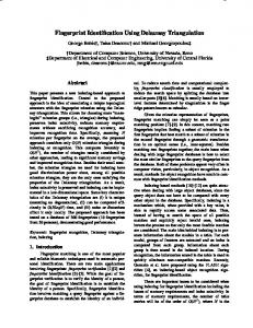
In this process, we used Gaussian Filter for operating over the image and reduce the extra amount of noise. The reason behind this filtering process is, to focus only the center pixel value of the filter size by taking all neighbor pixels into consideration, so that we have a stepper Gaussian field with less deviation value. If the operated Gaussian filters size reduced then it require more calculation, if it increases then required output can’t be match up to our expectation. So we are using a 5X5 Gaussian filter with σ = 1.4. Figure 1(a, b) shows the original image and its denoised image after application of the filter.
Figure 1(a) Original Image (b) De-noised Image.
2.1.2
Normalization:
Normalization is used to standardize the intensity value in an image by adjusting the grey level values so that it lies within a desired range. It is pixel wise operation which doesn’t change the clarity of ridges rather it reduces the variation of grey level value along the ridges. “Histogram equalization”, one of the general processes used to enhance the contrast of images by transforming its intensity values. On the other hand, it can equalize the unevenly distribute pixel in image and amplify noise producing worse result then the original image for low quality fingerprint. In our process, CDF (Cumulative Distributive Function) is applied to enhance and evenly distribute the pixel value. Here the function calculates the CDF value (using eq. 1) at each pixel position for a specific grey level range and then map the normalized value back to its respective pixel values. Figure 2 shows the histogram normalized image of the original image. So the basic CDF Function is:
( )
((
( ) )
( ) ( )
(
))
(1)
Where H(v) is output CDF value. ‘cdf(m)’ is minimum value of the CDF. ‘L’ is required grey level range.
Figure 2. Histogram Normalized Image. .
Where,
‘B’ is output image after convolution ‘A’ is input image.
2.1.3
Region Of Interest:
The Region of Interest (ROI) is useful to be recognized for each fingerprint image. The image area without effective ridges and furrows is first discarded since it only holds background information. Fingerprint pattern exhibits the area where ridge lines assume distinctive shapes. Such an area is known as core region. We consider this region for our purpose as, maximum of the features can found in this region. It is important to note when we traverse from center to edge, the number of feature points,
12
International Journal of Computer Applications (0975 – 8887) Volume 53– No.10, September 2012 present, decreases. As in our approach, we are concentrated on core based matching with no change in the core information with a certain degree of image rotation (i.e. ), this is possible because we are considering the direction of curvature technique for calculating the core region of the image. In this technique the whole image is divided into equal non-overlapping blocks (for our work the block size is 3x3). To understand in detail, the directional curvature technique algorithm is summarized as follows.
2.1.4
PROPOSED ALGORITHM: DIRECTIONALCURVATURE TECHNIQUE (DCT):
Divide the input image ‘I’ into non-overlapping blocks with equal size of w x w. Calculate the gradients strength ∂x(i, j) and ∂y(i, j) at each pixel (i, j) and the center of the block. The gradient operator can be chosen according to the computational complexity. But we are using sobel operator for our consideration.
ROI is the point which is not exactly present at the center but it is very nearer to center i.e. approximate center. This point will not change with image rotation as it prioritized its entire neighbor pixel for calculating the DC component of block level. After getting this point by considering some pixel in each direction the core region is formed. For our case we are considered 100 pixels in each direction so that it forms a 200 x 200 block of core region. Figure 3 shows the approximate core region of the original image.
Estimate the local orientation using the following equations.
( ) (
)
(
∑
)
∑
∑
(
∑
(
)
(
)
)
Binarization:
During this phase the gray scale image is transformed into a binary image by computing the global adaptive thresholding. This thresholding approach gives a particular threshold value for each image which we are consider for our simulation and testing phase. In this way each pixel of the core region is transferred to two different intensity levels as compared to gray scale image of 256 intensity levels. So the processing of binary image is easy. Figure 5 shows the binarized image of corresponding original fingerprint image. The disadvantage of binarization is that the ridges termination near the boundary is considered as minutia even though it is not actual minutia. The problem of binarization is eliminated in thinning process.
{
(7)
(2)
(
)
(3)
Where, 1. ‘P(x)’ Output pixel value 2. ‘T’ Threshold value of Global Adaptive Thresholding
and (
)
(
)
(
)
(4)
Here, θ(i, j) is the edge strength of the local ridge orientation of the block centered at pixel (i, j) .
Then the difference of directional component of each continuous block is calculated by following formula. ∑
(
)
∑
∑
(
)
∑
( (
) )
(5)
Figure 4.Binarised Image.
(6)
After this the image (shown in figure 4) is preprocessed and ready for further processing to identify its feature point and uniquely identify the image.
Then by comparing the directional component i.e. the list negative value in X-direction is considered as the point of concern. If can’t find core point of appropriate location. We decrease size of image and iterate the algorithm for core point detect again, until find core point or nearby point.
Figure 3.Approximate Core Region.
2.2 THINNING: It is the process of reducing the thickness of each line of fingerprint patterns to a single pixel width. Assurance of the thinning process described by (Patil et al., 2005). Here we are considered templates of (3x3) windows for thinning and trimming of unwanted pixels. In previous thinning process, the applied algorithm takes the image as an object and processes its operation. So that it mayn’t be possible to get the exact thinned image i.e. the line image into single pixel strength. But in our process we have considered each pixel as our object space and applied rules on its pixel level and try to remove the singular pixel as well as the unwanted pixels from fingerprint. These rules are purely observational and we consider all possibility to eliminate the unnecessary pixel from image and convert the image into single pixel strength. This thinning process acts iteratively on fingerprint. The maximum number of iteration
13
International Journal of Computer Applications (0975 – 8887) Volume 53– No.10, September 2012 depends upon thickest line of the image. We are using the 21 rule given (Patil et al., 2005) for thinning process by taking each pixel as a unique entity. In (Patil et al., 2005) choosing the position of the pixel i.e. considering the boundary line pixel is quite difficult, so we modified the algorithm and applied the rule from both directions iteratively still no change in iteration output to get an exact thinned image. Exact thinning is ensured when the pixel level of the ridge having only one pixel width. However, this is not always true. There some locations, where the ridge has two-pixel width at some erroneous pixels. An erroneous pixel is defined as the one with more than two 4-connected neighbors. Hence, before minutiae extraction, there is a need to develop an algorithm to eliminate the erroneous pixels while preserving the pattern connectivity. For this purpose an enhanced thinning algorithm is followed after thinning process.
2.2.1
Enhanced thinning algorithm
Step 1: Scanning the pattern of fingerprint image row wise from top to bottom. Check if the pixel is 1. Step 2: Count its four connected neighbors. Step 3: If the sum is greater that two, mark it as an erroneous pixel. Step 4: Remove the erroneous pixel. Step 5: Repeat steps 1 – 4 until whole of the image is scanned and the erroneous pixels are removed.
The process is rotation invariant and hence can be applied to any binary thinned fingerprint image. The sample templates are as shown in Figure 6.
Figure 6. Mask of all bifurcation point possible. After this stage it is necessary to eliminate false minutia. The main cause of false minutia occurs when thinning around whole results in a pair of false bifurcations. For eliminating such points a minimum threshold distance is selected and all the lines originating from the entire minutia are traced for that minimum distance, we may then eliminate those minutiae present within the minimum distance. It should be noted that the above distance following procedure does eliminate more false minutia than the few instances where real minutia are deleted (refer to figure 7).
2.3 FEATURE EXTRACTION: Minutia is characteristics of a fingerprint which is used for identification purpose. These are the points in the normal direction of the ridges such as ridge endings, bifurcations, and short ridges. Many automatic recognition systems only consider ridge endings and bifurcations as minutia. A reason for this is that all other structure like bridge and island structures are considered as false minutia. The advantage of using this assumption that, it does not differentiate between these minutiae. This is due to, when a real bifurcation is mistakenly separated, or if an end point mistakenly joins a ridge, it forms a bifurcation. There is no distinction made between the types of minutia rather their positions are considered. Figure 5 shows the minutiae position and its flow direction.
(a) Bifurcation Angle (b) Ridge termination Figure 5. Definition of minutiae points. The most accurate way of extracting minutia is from the thinned binary image where all ridges of print have been properly thinned to its central line. So for avoiding the time complexity and computational cost, we have used template based method to find out the points. The template is convoluted over the image to find exact position of the points. Here results obtained by rotating the thinned image by any angle are found to have the same distances between bifurcation points irrespective of its orientation. The point is considered as feature point if it connected to minimum three neighborhood pixel in its range.
(a) Thinned Image
(b) Marked Feature points
Figure 7. Accurate Feature point Identification.
2.4 MATCHING: In our process we constructed a spanning tree from calculated feature points. So the input to the spanning tree algorithm is the set of feature point. By calculating the Euclidian distance between the point, points are sorted for their level processing. Here the starting parent node is the node point calculated by DC technique discussed above. Each level contains the point having shortest distance between the parent and node. For calculation of the shortest distance, the loop will continue until it gets the terminating condition i.e. the end of the distance matrix table or it matches with the no. of feature point present over the region. If the loop comes to the terminating condition and there are some points left unsorted then it traverse back to its parent node and search for the next shortest point and assign it to the next level node and this process will continue until all point sorted. In this matching, we are considering the MST within the region of interest. Here we are focusing on the points present over a level. In each level the points are assigned with a particular weight value. Here we are considering up to the level 5.In level 1 the assigned weight is 0.4, level 2 it is 0.3, and for next respective level it is assigned with 0.1.These value are purely observational and assigned on the basis of the probability distribution. Here we are assigned the value as decreasing order due to priorities the parent node then the leaf node. Once the no
14
International Journal of Computer Applications (0975 – 8887) Volume 53– No.10, September 2012 of points are found out the value for a particular tree structure is calculated on the basis of its assigned value. This value is useful for the process of calculating the match point. Figure 8 Shows the MST structure and the probability calculation value for the MST. ( ) ()
Where,
(8)
‘Mp’ is Matching Score Point ‘P(m)’is total probability value of matched node in both images. ‘P(i)’ is Total probability value of ideal image.
percentage of two different fingerprints high then the false acceptance ratio of the technique also high. So in our proposed technique the acceptance ratio is less than other compared technique. Table 1 True and False Acceptance Percentage Proposed Algorithm
% of True Acceptance
% of False Acceptance
[A] .change in Intensity [B]. Shift(10 pixels) [C].Rotation (1o10o)
95.0
5.0
97.0
3.0
88.0
12.0
Table 2 Matching Percentage of two similar Fingerprints
Good quality Image Poor Quality Image
Ridge Technique
Minutiae Technique
Proposed Algorithm
100
100
100
92.342
96.991
97.880
Table 3 Matching Percentage of two different Fingerprints Figure 8.Tree Structure of the Nodes with Assigned Probability Value.
3. RESULT ANALYSIS This section describes a set of experiments for evaluating fingerprint matching performance of the proposed algorithm. In our experiment, the database NIST DB2 is considered for the performance analysis. Here we are comparing the proposed technique with 1) Ridge Technique 2) Minute Technique. The performance of minutiae technique is poor for low quality fingerprint images. The ridge based method has the disadvantage as the number of feature points for matching is very less so it may reject genuine fingerprints. In our proposed algorithm, the minutiae points are extracted using template filtering (convolution of the above discussed template over the image). We have considered 100 fingerprint images of different 20 subject each of 5 different instances of fingerprint sizes of 248 × 338 pixels. In the captured images, 10 of subjects have good-quality fingerprints and the remaining 10 subjects have low-quality fingerprints due to dry fingertips, rough fingertips and allergic-skin fingertips. Thus, the test set considered here is specially designed to evaluate the performance of fingerprint matching under difficult condition. Table1 shows the percentage of true acceptance and percentage of false acceptance of our proposed algorithm in different conditions. The proposed method has a percentage improvement in the range of 10 to 30 compared to existing algorithm. Here the Table 2 and Table 3 show the comparison of two different techniques with the proposed technique. In Table 2, it indicate the percentage of similarity of two fingerprint of a single person where as in Table 3 indicate the matching percentage of two different fingerprint. If the matching
Good quality Image Poor Quality Image
Ridge Technique
Minutiae Technique
Proposed Algorithm
7.142
8.755
5.773
11.11
12.335
7.223
4. CONCLUSION AND FEATURE WORK Fingerprint verification is one of the most reliable and secure method of identification process. In this paper we proposed Fingerprint identification based on the modified Tree Based Matching Algorithm. Here we have considered on the Directional Curvature Method of calculating the core region and then applying our Thinning and Template Filtering method to find out the exact feature points. These feature points are going to be processed in matching. The calculated feature points used for formation of tree and assigned the probability value to each level. Then the matching score point calculated to show the percentage of matching. This method of identification provides an easy and better accuracy of identification over other method. In Future, we are going to work on the fingerprint enhancement techniques and matching algorithm which can increase the accuracy of identification of low quality fingerprint image. Because the recent used technology on this feild, uses the input image quality to a certain level of acceptance. So if the quality of input degrades then false acceptance ratio of identification increases. So we are working on the development of a method which will try to enhance the poor quality of image up to that level of acceptance which will easily accept for identification and the FAR(false acceptance ratio) ratio will reduce.
15
International Journal of Computer Applications (0975 – 8887) Volume 53– No.10, September 2012
5. REFERENCES [1] Advances in Fingerprint Technology, H.C. Lee and Gaensslen R.E., eds. New York : Elsevier, 1991. [2] Sherlock B., Monro D., Millard K Fingerprint enhancement by directional fourier filtering, IEE Proc. Vision Image Signal Process. 141 (2) (1994) 87-94. [3] O'Gorman L., Nickerson J. “An approach to Fingerprint Filter design”, Pattern Recognition 22 (1) (1989) 29-38. [4] Methre B. “Fingerprint image analysis for automatic Identification”, Mach. Vision Appl. 6 (2-3) (1993) 124-139. [5] Coetzee L., Botha E.C., “Fingerprint recognition in low quality images”, Pattern Recognition 26 (10) (1993) 1441-1460. [6] Huang, D.C., 1993. “Enhancement and feature purification of fingerprint images.” Pattern Recognit. 26 (11), 1661–1671. [7] Jain, A., Lin, H., Bolle, R., 1997. “On-line fingerprint verification.” IEEE Trans. Pattern Anal. Machine Intell. 19 (4),302–313. [8] Lin, H., Wan, Y., Jain, A., 1998. “Fingerprint image enhancement:Algorithm and performance evaluation.” IEEE Trans. Pattern Anal. Machine Intell. 20(8), 777–789. [9] Anil K. Jain, Salil Prabhakar, Lin Hong, “A Multichannel Approach to Fingerprint classification”, IEEE trans. On Pattern Analysis and Machine Intelligence, vol 21, no. 4, pp. 348-556, April 1999. [10] Jain A.K., Hong L., Pankanti S., and Bolle R., “ An identity authentication system using fingerprints,” Proc. IEEE, vol. 85, pp 1365-1388, Sept 1997. [11] Maio D. and Maltoni D., “Direct gray –scale minutiae detection in fingerprints,” IEEE trans. On Pattern Analysis and Machine Intelligence, vol 19, pp. 27- 40, Jan 1997. [12] Prabhakar S., Jain A. K, Gianguo W., Pankanti S., Bolle R., “ Minutiae Verification and classification for fingerprint matching,” in proceeding of 15th International conference on Pattern Recognition, 2000, vol. 1, pp. 25-29, Sept. 2000. [13] Jain A. K., Ross A. and Prabhakar S., “Fingerprint matching using minutiae and texture features” in proceeding of International conference on Image Processing, 2001, vol. 3, pp. 282-285, 7-10 Oct. 2001. [14] Canbela G. T., Grother P. J., Watson C. I., Wilkinson R. A. and Wilson C. L., “PCASYS: A Pattern-level Classification automation system for fingerprints,” NIST Tech. Rep. NISTIR 5647, Aug. 1995. [15] Ranade S., Rosenfeld, A., 1980. Point pattern matching by relaxation.” Pattern Recognit. 12, 269–275.
[19] Patil M. P., Shekar R. S. and Faiyaz B. S. “Rotation Invariant Thinning Algorithm to Detect Ridge Bifurcations for Fingerprint Identification” 17th IEEE International conference on Tools with Artificial Intelligence (ICTAI’05) 1082-3409/05, 2005. [20] Lam L., Lee S. and Suen C., “Thinning methodologies- A Comprehensive survey,” IEEE transactions on Pattern Analysis and Machine Intelligence, vol. 14, no. 3, pp. 369- 387, 2000. [21] Dash T., Nayak T., Chattopadhyay S. Offline Handwritten Signature Verification using Associative Memory Net. International Journal of Advanced Research in Computer Engineering & Technology (2012): 1(4): 370-374. [22] Dash T., Nayak T., Chattopadhyay S. Offline Verification of Hand Written Signature Using Adaptive Resonance Theory Net (Type-1). In the proceedings of the 4th International Conference on Electronic Computer Technology (ICECT-2012 Vol-2) Kanyakumari, India (6-8 April’12). Editor: Yuan Li, pp. 205-210. ISBN: 978-1-4673-1849-5; DOI: 978-1-4673-1/12; IEEE catalog number: CFP1295F-PRT, IEEE Xplore. [23] Chattopadhyay S., Banerjee S., Rabhi F.A, Acharya R. U. A Case-based Reasoning System for Complex Medical Diagnoses. Expert Systems: the Journal of Knowledge Engineering (2012); published online DOI: 10.1111/j.14680394.2012.00618.x (in press). [24] Chattopadhyay S. A Prototype Depression Screening Tool for Rural Healthcare: A Step towards e-Health Informatics, Journal of Medical Imaging and Health Informatics (2012, in press. [25] Chattopadhyay S., Acharya U. R. A Novel Mathematical Approach to Diagnose Premenstrual Syndrome, Journal of Medical Systems (2012); 36(4): 2177-2186. [26] Chattopadhyay S. – ‘A Study on Suicidal Risk Analysis’. In proceedings of 9th IEEE Intl. Conf. on e-Health Networking, Applications and Service (HEALTHCOM 2007), pp. 74-79, Taipei, Taiwan (2007). [27] Panda S., Sahoo S., Jena P. K., Chattopadhyay S. Comparing Fuzzy-C means and K-means Clustering Techniques: a Comprehensive Study. In Proceedings of 2 nd International Conference on Computer Science, Engineering & Applications, by D.C. Wyld, J. Zizka, D. Nagamalai (Eds.), Advances in Intelligent and Soft Computing (AISC) Vol. 166, pp. 451-460. DOI: 10.1007/978-3-642-30157-5_45, 25-27 May, New Delhi India. [28] Satapathy S., Chattopadhyay S. Observation-Prevention of Cardiac Risk Factors: an Indian Study. Journal of Medical Imaging and Health Informatics (2012); 2(2):102-113.
[16] Chang, S.-H., Cheng, F.-H., Hsu, W.-H., Wu, G.-Z., 1997. Fast algorithm for point pattern matching: Invariant to translations, rotations and scale changes. Pattern Recognit. 29, 311–316.
[29] Chattopadhyay S., Sahu S.K. A Predictive Stressor-integrated Model of Suicide Right from One’s Birth: a Bayesian Approach. Journal of Medical Imaging and Health Informatics (2012); 2(2):125-131
[17] Mikl_os, Z., Kov_acs-Vajna, Z.M., 2000. A fingerprint verification system based on triangular matching and dynamic time warping. IEEE Trans. Pattern Anal. Machine Intell. 22 (11).
[30] Chattopadhyay S., Davis R.M., Menezes D.D., Singh G., Acharya U.R, Tamura T. Application of Bayesian Classifier for the Diagnosis of Dental Pain. Journal of Medical Systems (2012); 36:1425-1439.
[18] Jiang, X., Yau, W.-Y., 2000. Fingerprint minutiae matching based on the local and global structures. In: Proc. 15 th Internat. Conf. Pattern Recognition (ICPR, 2000) 2. pp. 1042–1045.
[31] Chattopadhyay S., Rabhi F., Acharya U.R, Joshi R., Gajendran R. An Approach to Model Right Iliac Fossa Pain using Painonly-parameters for Screening of Acute Appendicitis. Journal of Medical Systems (2012); 36(3):1491-1502.
16