17. Key Words and Document Analysis. 17a. Descriptors. Finite element, Contact
-Impact, Continuum mechanics. 17b. Identuiers/Open-Ended Terms. 4-4 l,.
U.S. DEPARTMENT OF COMMERCE Natiml Tedmcal Infmin Seiwe
AD-A030 280
FINITE ELEMENT FORMULATION AND SOLUTION OF CONTACT-IMPACT PROBLEMS IN CONTINUUM MEC;ANICS-IV
CALIFORNIA UNIVERSITY, BERKELEY
JULY 1976
I
Ii
BIBLIOGRAPHIC DATA
I1. Report No.
UC SESM
SHEET
76-L
3. Recipient's Accession No.
2.
4. Title and Subtitle
5. Report Date
FINITE ELEMENT FORMULATION AND SOLUTION OF CONTACT-IMPACT PROBLEMS IN CONTINUUM MECHANICS-IV
6.
July 1976
8. Performing Organization Rept.
7. Author(s)
T.J. Hughes, R.L. Taylor, J.L. Sackman, W. Kanoknukulchai
No. DOT-HS,5-OI235
9. Performing Organization Name and Address
10. Project/Task/Work Unit No.
Division of Structural Engineering & Structural Mechanics University of California Berkeley, California 9h720
11. Contract/Grant No.
N68305-75-C-O0A 0 13. Type of Report & Period
12. Sponsoring Organization Name and Address
Civil Engineering Laboratory, Naval Construction Battalion
Covered
Center, Port Hueneme, CA; National Highway Traffi.c Safety
_
Administration, Dept. of Transp.;Office of Naval Research,
14.
Arlington, Virginia 15. Supplementary Notes
_
None 16. Abstracts In this report we describe work completed under Subcontract No. N68305-C-01 4. In Section I w: present theory and algorithms for large displacement contact-impact analysis in two limensions (i.e. plane stress, plane strain and axisymmetric). The theory encompasses a wide range of contact-impact problems and allows for a completely arbitrary contact surface development, stick, slip and frictional slidinf conditions, and inpact-release conditions covering the full range of contact possibilities.
In Tection II we describe some new developments regarding the Hertzian algorithm. SectiCn III contains sample problems which employ the algorithms described in Section I and also some studies involving the Hertzian algorithm. Anticipating the need for an efficient shell element for crash configuration
modelling, we have performed a pilot study of a plate bending element.
'he results
of this study, which are encouraging, are contained in Section IV.
17. Key Words and Document Analysis.
17a. Descriptors
Finite element, Contact-Impact, Continuum mechanics
17b. Identuiers/Open-Ended Terms
4-4
S IKT TO
l,. COSATI Field Group
i
18. Availbility Statement
Available to general public
19. Report) Securtv Class (This h eUCrAt 20. S
FtORM
NTf$-3?
'REV
10-73,
LNIX)RSED BY ANSI AND I %FS01).
Rcu rity (4)l
THIS FORM MAY BE-. REPRODU(F.)
OIG" E
21. No. of Pages
cou22. Price USCOMIJ.o¢
6265-714
V
278123
1%Pt N.
UC SESM 71-4
STRUCTURAL EIIEERM AND STUTMUNAL
q:
FINITE ELEMENT FORMULATION AN SOLUTION OF CONTACTIMPACT PROBLEMS INCONTINUUM MECANICS-X
Oc
U O
by THOMAS . HUGHES ROBERT LTAYLOR JEROME L. SACKMANIt WORSAK KANOI(NUKULCHAI
--
:
,t
SEP? LAi
JULY 1976 4
__OlB.....TMFET OF !IVII FlICUEEIC
Ol VERIITY OF CALIFORNIA BERfKELEY, CALIFORNIA
i
REPROOUCED BY
NATIONAL TECHNICAL INFORMATION SERVICE U S DEPARTMENT OF COMMERCE SPRINGFIELD. VA. 22161
" ' -
us O(ART~m Orco.,e~-
-
Xji L
,"Division of Structural Engineering and Structural Mechanics Department of Civil Engineering Report No. 76-4 FINITE ELEMENT MODELS FOR LARGE DISPLACEMENT CONTACT- IMPACT ANALYSIS by Thomas J.R. Hughes Robert L. Taylor Jerome L. Sackman Worsak Kanokriukulchai
~~N68305-
This report was prepared under subcontract number 75-C-°004 sponsored by
Nl
ICivil
Engineering Laboratory Naval Construction Battalion Center Port Hueneme, California
[I"
as part of NHSTA interagency Agreement Number
I,
DT-HS-5-O1235
Funded by National Highway Traffic Safety Administration Department of Transportation
-
~~~~~~and
.-
;J +.
J tP
6;,
22 t6 L
Funding Document Number ONR 76-WR-60083 Funded by Office of Naval Research Arlington, Virginia
July 1976
"I'D
-.
e~at----
iLPioTodNulot~b~~rg*5 unahited
14
Table of Contents Page Acknowledgment .......
............................
Introduction ....... ... I.
...........................
Large Displacement Contact-Impact Theory .....
1.
Introduction .
.........
..........
...........
2. Local Structure of the >:Jations .....
ii 1 2 2
............
3
3. Computing Strategy W6:tin a Time (Ljad) Step ........ 8 4. Impact-RelIfease Conditions
.
...........
.
a. Stick Contact Condition ... b. Sliding Contact Condition ...
.
14
................
14
................
c. Frictional Contact Condition .....
............
18 19
II. New Developments with Particular Reference to the Hertzian Algorithm ........ 1. Introduction ......
.....................
...................... ...
2. Automatic Time Stepping .......
...............
3. Higher-Order Impact-Release Conditions .... III.
Sample Problem .......
33 33 33
.........
35
........................
42
1. Identification of Urethane-Polystyrene Composition Foam for the Nonlinear Continuum Element ..
............. 42
2. Equivalence of Present Incompressible Formulaton with a Mean-Pressure-Variable Element .....
............
43
3. Quasi-Static Analysis of a Skull.-Pad Contact Configuration ......... *
....................
IV. A Simple and Efficient Finite Element for Plate Bending 1. Introductiur, ... . ..
52
..................... .... 52
2. Example: Linear Beam Element ...
Zi
44
.............. ...
55
3. Bilinear Plate Bending Element ..... 4. Numerical Examples: Thin Plates ..
.............. .............
5. Numerical Sensitivity due to Extreme Thinness .. 6. Application to Thick Plates ..... 7. Conclusions ....... References .....
...
..
62 64
...... 69
...............
71
.......................
73
............................
90
Acknowl edment This repcrt was prepred under Subcontract No. N68305-75-C-004; sponsored by Civil Engieering Laboratory, Naval Construction Battalion Center, Port Hueneme, California as part of NHSTA Interagency Agreement Nunbter DOT-HS-5-01235, funded by the National Highway Traffic Safety Administration of the Department of Iransportatlon, and Funding Document Number ONR 76-WR-60083, funded by the Office of Naval Research. The opinions, findings and conclusions expressed In this publication are those of the authors and not necessarily those of the Civil Engineering Laboratory, the National Highway Traffic Safety Administration, or the Office of Naval Research.
4f
.
ifAi
.
.
4
Introduction SIn
this report we describe work completed under Subcontract No. N68305-75-C-004 (Proposal UCB-Eng.-3889).
As we frequently refer to our
previous work [1-5], it will prove helpful to the reader to be somwhat familiar with these references. In Section I we present theory and algorithms for large displacement contact-,impact analysis in two dimensions(i.e. plane stress, plane strain and axisymtric).
This work builds upon earlier developments documented in
[2] and [3] and represents the completion of our theoretical work in this area.
The theory encompasses a wide range of contact-impact problems and
allows for a completely arbitrary contact surface development, stick, slip and frictional sl*ding conditions, and impact-release conditions covering the full range of contact possibilities. In Section II we describe some new developments regarding the Hertzian algorithm, which has been extensively documented in previous publications; see [1-5]. Section III contains sample problems which employ the algorthins described in Section I and also some studies involving the Hertzian algorithm. Anticipating the need for an efficient shell element for crash configuration modelling, we have performed a pilot study of a plate bending element. The results of this study, which are encouraging, are contained in Section IV.
iI )I
2
I. Large Displacement Contact-Impact Theory 1.
Introduction In the following sectiov' we present a large displacement contact-impact
theory.
In Section 1-2 we set notations and establish the structure of the
local equations for a typical contactor node and target element boundary. The algorithm for handling stick, slip and frictional contact conditions is discussed in Se.lion 1-3.
This strategy is sufficient for the quasi-static
problem and governs the iterations within a time step in a dynamic problem. The updating ir dynamic problems manifested by discrete impact-release conditions is described in Section 1-4.
!S
3
2. Local Structure of the Equations To explicate the structure of the equations we wish to solve, we shall consider in this section an idealization consisting of one ccntactor node and one target element boundary (see Fig. I-1).
Quantities associated with
the contactor node will possess a subscript k, and those associated with the target nodes will possess a subscript Z or +l. Throughout this section we shall concern ourselves only with equations which pertain to these three nodes.
In two-dimensional analysis (i.e. plane stress, plane strain or
axisymmetric) there are two displacement degrees-of-freedom associated with each of the three nodes and, in addition, two contact force degrees-offreedom associated to the contactor node; a total of eight degrees-offreedom for the three nodes considered here.
Thus there are six equations
of motion to be satisfied and, if the bodies are in contact, two cordiLions of compatibility.
Consider the case in which the contactor node is in
contact with the target element boundary.
Then if a is the nondimensional
location parameter for the target element boundary, defined by (see Fig. 1-2):
(xlk
x1 )2 + (X2k
-
x2
2] 2
2 L
[x,
/) /L 211/2
x2 )
+ (x
the eight equations to be satisfied for the three nodes are:
*
I
where
-
+
+
+
:
4 ~2
m :M 0
0
0
o
, the mas
_ss,
1 2
Lo
(u kk
(
T ,
K2
2
yk
0
K
=
(Tyk
0
-(l-a) Yk
=Y
(o{x
ky
they.+l displacements,
1
K K,+lT ,) the internal forces,
)T , the contact forces,
-a
and
k
('-)
x2
y
the compatibility conditions.
aX2 Y, E+l
o
0, ,
)T,
The superscript indicates to which body the
quantity pertains and the subscript y indicates the coordinate direction z
Y
,
y = 1,2.
l Note that the components K and K2 are functions ot the dis-
placements of B1 and B2 , respectively. The compatibility conditions amount to the second and sixth equations in I-1.
and Tyk
When the bodies are not in contact these conditions are ignored 0o
The solution of the matrix equations is developed by employing a temporal discretization which results in a nonlinear algebraic problem to be solved at each time step.
The Newmark family of algorithms is employed
by us to temporally discretize the equations and we confine our attention to implicit methods.
This aspect of our work has oeen described previously
(see e.g. [5]) and we shall not repeat the details here.
The resulting
temporally discretized system, for the nodes in question, becomes:
I ~
Vr'
- _]_____I k*
I
S
1
z] n+l
:
[
a t
2 n+l
2 n+i
:InlY2-n
at
At
iL
21
+1-2s 2a
where the subscripts n and n+l indicate the time step at which the quantity time interval, and a is is evaluated, At - tn+l - t n is the length of the the Newmark parameter. time step, the ewtonTo solve the nonlinear algebraic problem at each used in this procedure, Raphson method is employed. The linear equations for the nodes in question, are given as follows: k* Aw()
(1-3)
= r* ,
where m k*
k
o
0
+ D
2
o
m
-S
[Zkj
n+l
:21
M
6
L-2J n+l
t2 nl
+
+1-2a 26
tA F] :(
[-21 n+l
21a+ BAtL-2jn
\_j [2jn
:,
1 a At 2
L2j n
-jn+l
where the superscript in parentheses indicates the iteration number and
D
E2
denotes the tangent stiffness matrix. The formation of the tangent stiffness follows the standard rules (inparticular, in the case of linear elastic' bodies it is the usual stiffness matrix).
The iterative process is defined
by •(o) Wn+ 1
•
W -n
(i+l) = -n+l
and when w
i)
(i)++ A"M n+l n+l
satisfies a convergence test, fr some i, then Wn+l
Here w is defined by (o
I+ lk
0
0
2k
0
0
def.
(i)
w
The matrix
(12.
is called the contact stiffness.
L-i2j n+l
Specification of it,
L2
n+l
are the unique aspects of the contact-impact algorithm.
In the next section
we describe the way this is done. In passing, we note that formally setting T to o provides an algorithm for the quasi-static case.
8 3. Computing Strategy Within a Time (Load) Step ~In
this section we describe the strategy involved in solving the non-
linear algebraic contact problem within a time step (or, equivalently, within a load step in the quasi-static case).
The unknowns involved, as described
in the previous section, are the displacements and contact forces at the end of the step. Treatment of velocities and accelerations, and updating of contact forces, when impact and release effects are present, are considered in the following section. For consideration of sliding contact, it is convenient to work in a coordinate system naturally defined by the target segment. A system of this kind can be constructed by aligning the coordinate axes in the tangential (s)and normal (n) directions to the target element boundary, with origin located at node z (see Fig. 1-3).
If e denotes the angle between the s and
z axes, measured counterclockwise from zi, then e = arc tan [(x 2 , +l
x2,)/(Xl, £+I
-
x1 ,)]
and vectors may be resolved in the usual way into tangential and normal components, e.g.
where c = cos 6 and s = sin 6. Thus the vectors in the s, n corresponding to !l and S
n
-
system
Tare
sk
0
-(l-c)tSk
-a
(Tnk
o
-(l-a)Tnk
-a Tnk
respectively, and likewise for xs and
n"
Tsk
and
____________
_
-
~
9
At the end of each iteration, one of three conditions can hold for a typical contactor node k; the condition is determined by the contactor code ik .
If Ik = o, then contactor node k is not in contact; if ik > 0, then
node k is in contact.
The code ik
=
1 signifies the stick condition and
i k = 2 signifies the sliding condition.
The contact code determines what
is assembled into the contact stiffness and the right-hand side vectors
I
)
and x.
Specifically, we have the following situations:
I
o(i)= _k
-Y
; (i) =
I-Y i
-Y 2:
_
-Y
=
9n
in
_n
(i) M
inty
(i)+
(i +0A
-s n
=n
;(
T
-"Y
10
-
where
r
0
1
1
0
o0
Ir, =
0
0 -(l-a)
-a
-(I-a)
0
o
0
-a
0
0
o
0
0
0
o
1
0
0
0
0
0
0
0
0
0
0
nkI
-( -z
nk I -o I nk I)
and f is the dynamic coefficient of friction.
Rotation of quantities in
local coordinates into global coordinates is facilitated by the following transformations:
[;o
2TT :2]
=.
[s
:]
q-
T
-0 nl
in which F
T
C
0
0
0
S
0
0
0
0
C
0
0
0
S
0
0
0
0
c
0
0
0
S
0
0
0
0
c
0
0
0
0
-S
0
0
0
c
0
0
0
0
-S
0
0
0
c
0
0
-S
0
0
0
C
0
-S
0
0
0
C
0
0
0
0
0
II
and
x
=
-2
s
-
s x
s xs =
2
cX
C s
=
T
n
-+CXn -
S Tn
+
cTn
The determination of the contactor code i k for the present iteration depends upon "its value for the previous iteration. If i k was equal to o, then node k was not in contact during the previous interatlon.
In this case we must determine whether or not node k has pene-
trated a target segment during the present iteration. location of node k and let x.l
,
x,,
Let x k denote the
xL+l denote the locations of consecutive
target nodes z-I, t, +l, respectively, where t designates an interior node of some segment.
We assume that the entire list of interior target nodes
has been searched and k is found to be closest to t at the end of the present iteration.
For node t the interior of the target is defined to be that part
of the plane consisting of the two straight lines emanating from x. through and x +l and extending to infinity, and all points to the right of these lines with respect to the target direction. remaining portion of the plane (see Fig. 1-4).
The exterior is the
At the end of an iteration,
if x. is in the interior of the target we say that tentative contact has been made.
To determine if this has occurred we employ the following
algorithm (see Fig. 1-4 for notation). Let A = (xk,
xz 1 , xz. xt+ 1) and define TEST as indicated in Fig. 1-5.
Jf the outcome of TEST is true (1), then xk is exterior to the target, whereas if the outcome is false (F), xk is in the interior and tentative contact has been made.
In the latter case further calculations are required
12 to dete.ine if indeed contact has occurred* and, if so, where. routine to carry out these calculations
The
requires the input parametersimx
and j Max, which are the maximum number of iterations allowed to determine the epproximate location of a contact point, and the maximum number of changes of target reference node allowed, respectively.
If tentative
contact h~s been made we next employ a binary search procedure to determine a good approximation to the-configuration 8 at which initial contact was actually made. With this confi.uration determined, we ascertain whether node k actually contacted the segment defined by target nodes t-1, Z, £+l
(II
< 1) or did not (jcz
> 1).
In the former case we set the new value
of the contactor code ik to 1, whereas in the latter we may try another reference point and repeat the calculation.
However, if jmax has been
reached, or the new reference point is a target segment boundary node, we assume no contact has been made and set ik to o. The following is a brief description of the main points of the flowchart depicted in Figs. 1-6 to I-11. if ik was greater than zero for the previous iteration, then contactor node k was in contact.
In this case it is first checked if the updated
normal component of traction Tn is compressive. then ik is set to zero.
If Tn is compressive, then it is determined
whether contactor node k was sticking ( (i
= 2) during the Idst iteration.
value of
IT
I
is compared with
coefficient of friction.
If this is not the case,
If ITs!
t
=
1) or whether it was sliding
If it was sticking then the updated =
fs Irnl' where fs is the static
"crit' -
then i k is set equal to 2;
otherwise i, is set to 1. If noje k was sliding during the last iteration then a new value of a is computed based upon the updated configuration.
If
A contactor node can enter the interior without passing through the target, e.g. by sneaking around a boundary node.
13
11, then ITs is compared with
fd ITnI
T crit
The result of this
comparison determines whether contactor node k is sliding or sticking, as above.
If Ial l,the target reference node is rhanged to the appropriate
adjacent one, A naximum of ismax changes of reference are allowed. (The default value of i
smax
is one).
If i
smax
is exceeded, the computation is
terminated and an error message is jrinted.
If in cha,,ging the target
reference node a target segment boundary node is encountered, the no contact codeik is set to zero.
1TsI
If a value of a is found such that IaI s 1, then
is compared with Tcrit = fd ITnI and we proceed as described above.
When contactor nodes slide over target nodes, the comput3tion of the new values of a is approximate,
unless the target segment is 'at.
Thus some
caution is advised in application to prnblems in which substantial sliding is likely during a time (load) step.
f
I I
14
4.
Impact-Release Conditions Imposing correct impact and release conditions are essential ingredients
in the accurat( solution of dynamic contact problems.
The present developments
extend earlier work (see [1-5]) in which s-.,.ple node on node normal incidence was considered.
In this section we describe procedures for setting
impact-relea3e conditions for the stick, slip and frictional cases.
Since
each of the cases differs somewhat from the others we discuss them one at a
time. The stick case ib the most straightforward and we shall describe it first. a.
Stick Contact Condition We consider the case of an open target segment consisting of N2 nodes
*
( ,esuperscript refers to body number 2). The case of a closed target follows trivially. We allow for the possibility of an arbitrary number of contactor nodes impacting and/or releasing the target segment over the time step. The updating of nodal velocities is determined from the following two conditions: (1) The velocity of a contactor node in contact with the target segment is the linear interpolate of the target node velocities of the element boundary in question.
For instance, consider the configuration of
Fig. 1-2 in which contactor node k is in contact with the element boundary defined by target nodes z and z+l.
In this section we will attach
a sub-
script to the nondimensional location parameter to indicate that it is associated with contactor node k, i.e. we denote it ck"
If 6k denotes the
velocity vector of contactor node k, and u and 6,.+l are the velocity vectors
of tArnet nnoe
o And 0+
racnartive1y
fhan fha
cnitInn
of linear
interpolation requires u
k(-
(1-0)6 + ak i0
(1-4)
-
-_______________I_ ,
.A,-....
.
°
-
-
15
Observe that this definition remains meaningful when there are more than one contactor nodes in contact with a single elemner.t boundary. (2) Tha second condition is a discrete impulse-momentum balance. Let AI denote the tributary area surrounding target node t. Specifically, this area is defined to be one-half the length of the two adjacent target element boundaries to node t, in case node
2
is an interior node; and one-
half the length of the adjacent target segment, if node k is a target segment Let C denote the set of contactor nodes in 1 contact with A at the end of the time step (last iteration), and let C-
boundary node (see Fig. 1-12).
k
I
denote the set of contactor nodes which were in contact with A. at the pc-qinning of the time step, but which released during the time step. Then 2 f.' each z
{1,2,...,N 21 we require that k Y k + 2~
+
M, +I kE C
Tk
kEC-1
kE C
MkuC c
(1-5)
-1
16
and for each kEC- 1 we require Mc
*c +
-1 At
where the superscripts + and -l indicate the updated values and values from the previous time step, respectively, M' indicates the lumped mass coefficient CI
.. of target node t and Mc is the lumped mass coefficienft of cont-ato-r
Equation (1-6) defines
for all kE f+
the previous step; namely u"k and T-1.
C1
i
d
terms of the data from
k.
Equations (6.1) and (6.2) lead to
the following system of equations for the target nodal velocities: AU
=B
(1-7)
W .
16 where A is tridiagonal with nonzero coefficients N2 }
Mc M (1 - k , tt- {2,13,..,
a , X-1
a,,
=
k
Cleft
Mk)lf+
Mt + kc
(
k Cl)eft d
h
kE(
k V
right
M (l-c k),
L€
{1,2,3,...N2 I
N2-1U
E {1 ,2,3,.
k E (C) P,right and
b12
ub +
+
U. 21
u22
b21
+ ."
+
.
KN2
UN22
I
b22
bN21
bN22
in which
Mt -1 ++c =Mzu
-1 + At Mkk M U
E
I -12 E {1,2,..., N2 }
Tk
The subscripts 'left' and 'right' on the C's indicate the subsets of C
to the left and right of target node t, respectively. The second subscript on the entries of U and B refer to the coordinate
direction, e.g. bz2 is the z2 - component of b .. An argument which employs dynamic force balances in place of impulsemomentum conditions yields relations for updated accelerations and contact
17
forces.
The end results are summarized as follows:
The updated accelerations of the target nodes Z, are determined by solving A U = B'
(1-8)
where
11
u
u
bl,
u21
u22
b2
22
'i
12
B'=
I~U=
L. 2
22L UN
+
kE C-
bNl Mk k
ke C
bN2 2 1
l
In the above definition of b , the superscripts refer to tne last iteration. • The updated accelerations of the contactor nodes which are in contact with the target segment are given by linear interpolation, i.e.
(I-k) u + Ck uY+l
uk
The updated accelerations of contactor nodes which have released from the target sometime during the time step are given by
k
-V.-.---
'--
k
-i----
T
(1-9)
18
The updated contact forces associated with nodes which are in contact with the target are given by - + Mc" +
-- k +~T-k
k (-k
-Uk)"(
-O 0~M(i-~.(-10)
The solutions of the systems of equations (1-7) and (1-8) are accomplished most efficiently with an unsynmetric
tridiagonal solver. *rhe
following is a FORTRAN subroutine to carry out this procedure.
The matrix
A is stored by rows as a one-dimensional array. SUBROUTINE TRISOL (A,B,NEQ) DIMENSION A(1),B(NEQ,2) C ...
REDUCE EQUATIONS TO UPPER TRIANGULAR FORM
NM =3 * NEO-2 1=2 DO 100 N = 1, NM, 3 IF (A(N). EQ. 0.0) GO TO 100 AA = A(N+2)/A(N) A(N+3) = A(N+3) - A(N+l) * AA B(I,l) = B(I,l) - AA * B(I-I,1) B(I,2) = B(I,2) - AA * B(I-l,2)
100 C ...
200
1=I
+I
BACKSUBSTITUTE
I = NEQ IF (A(NM). EQ.O.O)
GO TO 210
B(I,l) = B(I,I)/A(NM) B(I,2) = B(I,2)/A(NM)
210
1 = I -I IF (I.LE.O) RETURN N = NM-3 B(l,1) = B(I,l) B(I,2) = B(I,2)
-
A(NM+l) * B(I+I, 1) A(NM+l) * B(I+I, 2)
GO TO 200 END b. Sliding Contact Condition The impact and release conditions for the sliding contact (frictiolless) case are similar to the stick case, but only involve normal components. To describe the procedure employed, we will need to introduce some new terminology.
Local boundary coordinates are normal (n)- tangential (s)
coordinates attached to each target element boundary (see Fig. 1-3). Pseudo-normal coordinat., for an interior target node z are normal (n)-
19
tangential Cs) coordinates with respect to the line joining target nodes t-I and
+l, whereas for target boundary nodes they are the same as the
local boundary coordinates (see Fig. 1-13).
All computations of impact and
release data are done with respect to the configuration determined by the last iteration within the time step. The velocity update is achieved as follows: Transform all ''s and T's appearing ir.'1-5) and (1-6) to pseudo-normal coordinates. Solve (I-7) where B is replaced by the analogous N xl vector U will then be the updated a-components of
of normal (n)components.
velocity of the target nodes. procss. Roatethe6,
(The s components are unaffected by this Obtain
-coponntsinto local boundary coordinates.
the boundary normal (n)components of the contactor velocities by linear interpolation of the updated n-component target velocities, are unaffected,)
For nodes which Iav
(The s-components
released, equation (1-6) is to be
applied with the n-components. Accelerations and contact forces are updated as follows: of B', Rotate the W's and
i's appearing in the definition
(I-10) into pseudo-normal coordinates.
(1-9)
and
Solve (1-8) where B' consists only
of the h-components; U will be the updated n-components of the target node accelerations.
t
The i-components are unaffected. Rotate the n, s-components into local boundary coordinates and linearly interpolate to determine components are unaffected.
4. k
The s-
Updated n-components of contactor nodes which
have released are given by (1-9) with k replaced by
.
Updated n-component
of cortact force are given by (1-10) with k replaced by n.
As before, the
contact force fur released nodes is zero. c. Frictional Cut.tact Condition The impact ani release conditions for the frictional case are identical,
*
20
for the n-components, to the frictionless case. modifications are required.
For the s-components some
In the ensuing discussion we consider only the
s-components. Again systems similar to (1-7) and (I-8) are coastructed. Here, let C denote the subset of nodes in contact which are not sliding at the last iteration of the time step, and let ClI indicate the released nodes (including sliding nodes). of
Then, in the updating of velocities, s-components
k should be replaced by the s-components of K(
.+
k) where
is a
shear correcticn factor which can be adjusted to accurately capture shear wave phenomena.
In the present work we assume for simplicity
remarks pertain to equations (1-5) and (1-6).)
K =
1.
(These
The si-components of velocity
for the nodes in C are computed by linear interpolation. The updating of the i-components of acceleration and contact force proceeds as follows: Formulate the i-component of B' using u and T
Then U will be the
updated i-components of acceleration fur the sticking nodes.
Released node
s-accelerations are given by (1-9), and non-sliding node updated s-contact forces are given by (1-7). of s-components of u and T.
For nodes which are sliding there is no update
21
CONTACTOR NODE
Y
TARGET ELEMENT BOUNDARY
FIG. 1-1
TYPICAL CONTACTOR NODE AND TARGET ELEMENT BOUNDARY
-4-
-4-
-4-
FIG. 1-2
NONDIMENSIONAL LOCATION PARAMETER
22
iZ Z2
FIG. 1-3
TARGET ELEMENT BOUNDARY LOCAL COORD INATE SYSTEM
1 I
23
R1 EXdERIO /n
INTERIOR
FIG. 1-4
TYPICAL CONFIGURATION FOR CONTACTOR POINT AND TARGET SEtGiENT REFERENCE POINT x
24
I
START
EXTRIO
TO THE TARGET
25
r
-
START K-
I, N
RETURN
a-"* -*j+Ix2*,b-o"x*+I -xil L--(o2 +b2 )"2, sinG-i- a/L,cos9- b/L r,-
-sim~r, + cos
Br2
N
F
FIG
1'6
CHA
FLO
TIC
LAESTRB
THEOMPUITERATG IHN TIM A
70
~
(LAD, SE
26
5
CONTACTT
FIG.
o-
271
30
A+-- A'
>
4
40
Ii
BINARY SEARCH ALGORITHM TO
A-A++/
DETERMINE
LOCATION OF CONTACTT CONFIGURATION
TS
IF
A+
FIG. 1-8
28
CHANGE O TARGET40 REFEENCE_______T NODE~
FIG 1-9d
29f
50
a1-L. 0L f
CL
020
-
22
z
-
-~
LfL J
-z *1
-I
10
IN3iVd3:)VidSIO 11~bN3)NI
0
80883 1 N3:83,d
0
.j
~
JL
C
78
z
w -j
C
C
>-
La LnCL z,
~
Lw uZ
z
U-
U-
I-
uj
-
C
.)J
LJ
t~
=-
u~
C)
C
79
z 2 I-
2 00 C)
L
C
ICD
oo
CQ
0
o0
-
-
0-j
0
iC
0
1N3kNJ2DV-dSIOI dli O3ZI-VVY8N
U
rO
80
Iw
ac
+
0 -.
-
I
I
-inP.
.L&J
3E
IC
O
ja
:
u~
LAJC/, 0 Uo-
L w%0
--
00
iN3V433V1dSIO 831N30 03Z$'VY48ON
r.
J M.O
A
I Lf)
025
0
050
075
0
T
101
Ix 2.0
x
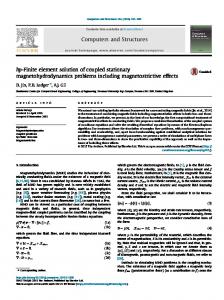
EXACT SOLUTION (REISSNER'S THEORY) ONE -POINT SHEAR INTEGRAT ION
qR 4
FIG. IV-8
CLAMPED CIRCUJLAR PLATE SUBJFCTED TO UNIFORM1 LOAD (43 ELEMENT MODEL).
COMPARISONI OF
UNDEIiNILGRATED SHEAR ELEMENT WITh EXACT SOLUTION
R
r
82
00 LAJ
w. U:- xA
1- co
-j..CC LL
0
0
0
o
6
6oC CL CO.
z
0
aI--
0D-
1-0U 0
on
4
0
D
o
0
0
w
z z
0
w
LJ.
*tjLin
CD I
*
~ ~~~
V
-
-- .
~
. ... .
83
01
C\N(D 0-
p.
IC)
x
o
-
0
I
I x
-4
--
~
LD
-------
C
~----------.-------------
84
Ixa
Nv
0
0-
I,
U-
Ka
.-
in0
.
f
85
U,
00
00
-0O
...........
C.-
86
0
xo
0c 00
0
00 72
I')k
(.D
87
0
66
0
In
88
F0 z 0I
04
x
LU
0
0 00
0 0
0
0
(D
-~N I..
-
w-
T
0
04
0
o o
0
(D o.
0
89
IN 'C
zi
04
-C,)
i
U) D
o
C>
00 LU
w
-~
LUJ
u
90
References 1.
T.J.R. Hughes, R.L. Taylor and J.L. Sackman, "Finite Element Formulation and Solution of Contact-Impact Problems in Continuum Mechanics." SESM Report No. 74-8, University of California, Berkeley (1974); copies can be obtained from National Technical Information Service, Springfield, Virginia, 22151, Accession No. PB-233 888/AS.
2.
T.J.R. Hughes, R.L. Taylor and J.L. Sackman, "Finite Element Formulation and Solution of Contact-Impact Problems in Continuum Mechanics - II." SESM Report No. 75-3, University of California, Berkeley (1975).
3.
T.J.R. Hughes, R.L. Taylor and J.L. Sackman, "Finite Element Formulation and Solution of Contact-Impact Problems in Continuum Mechanics - III." SESM Report No. 75-7, University of California, Berkeley (1975).
4.
T.J.R. Hughes, R.L. Taylor, J.L. Sackman, A. Curnier and W. Kanoknukulchai, "Finite Element Formulation and Solution of a Class of Contact-Impact Problems in Continuum Mechanics." Transactions of the 3rd International Conference on Structural Mechanics in Reactor Technology, Paper J5/5, London (1975).
5.
T.J.R. Hughes, R.L. Taylor, J.L. Sackman, A. Curnier and W. Kanoknukulchai, "A Finite Element Method for a C1.ss of ContactImpact Problems." Comutational Methods in Ai',hed Mechanics and Engineering (to appear).
6.
J.D. Brooks and L.G. Rey, "Polystyrene-Urethane Composite Foam for Crash Padding Applications," Journal of Cellular Plastics, Septermber/October, 23? (1973).
7.
T.J.R. Hughes and H. Aliik. "Finite Elements for Compressible and Incompressible Continua." Proc. Symp. Civil Eng., Vanderbilt University, Nashville, Tenn., 27-62 (1969).
8.
T.J.R. Hughes, "Equivalence of Finite Elements for NearlyIncompressible Elasticity" (to appear).
9.
T.A. Shugar, "Transient Structural Response of the Linear SkullBrain System," Proceedings of the Nineteenth Staop Car Crash Conference, San Diego, California, November, 581-614 (1975).
10.
O.C. Zienkiewicz, The Finite El McGraw-Hill, iew York (1971).
11.
R.H. Gallagher, Finite Element Analysis Fundamentals. Prentice-Hall, Englewood Cliffs, New Jersey (1975).
12.
R.D. Cook, Concepts and Applicatio-i, of Finite Element Ana.Isis, New York (1974). John Wiley and Sons,
ent Method in Engineering Science,
91
13. B.M. Irons and K.J. Draper, "Inadequacy of Nodal Cor.;ections in a Stiffness Solution for Plate Bending," AIAA J, , 961 (1965). 14.
R.J. Melosh, "Basis for Derivation of Matrices for the Direct Stiffness Method," AIAA J, j 1631-1637 (1963).
15.
G.P. Bazely, Y.K. Cheung, B.M. Irons and O.C. Zienkiewicz, "Triangular Elements in Plate Bending--Conforming and NonConforming Solutions," Proceedings of the (First) Conference on Matrix Methods in Structural Mechanics, Wright-Patterson Air Force Base, Ohio, 547-576 (1965).
16.
R.W. Clough and J.L. Tocher, "Finite Element Stiffness Matrices for Analysis of Plate Bending," Proceedings of the (First) Conference on Matrix Methods in Structural Mechanics, Wright-Patterson Air Force Base, Ohio, 515-545 (1965).
17.
B. Fraeijs de Veubeke, "A Conforming Finite Element for Plate Bending," International Journal of Solids and Structures, 4, 95-108 (196).
18. K. Bell, "A Refined Triangular Plate Bending Finite Element," International Journal for Numerical Methods in Engineering, 101l-122 '(I969). 19.
G.R. Cowper, E. Kosko, G. Lindberg and M. Olson, "Static and Dynamic Applications of a High Precision Triangular Plate Bending Element," AIAA J, 7, 1957-1965 (1969).
20.
G. Butlin and R. Ford, "A Compatible Triangular Plate Bending Finite Element," International Journal of Solids and Structures, 6, 323-332 (1970).
21.
T.H.H. Pian, "Element Stiffness Matrices for Boundary Compatibility and for Prescribed Boundary Stresses," Proceedings of the (First) Conference on Matrix Methods in Structural Mechanics, WrightPatterson Air Force Base, Ohio, 457-478 (1965).
22.
G. Wempner, J.T. Oden and D. Kross, "Finite Element Analysis of Thin Shells," Proceedings of the American Society of Civil Engineers, Journal of the Engineering Mechanics Division, 94, IZ73-1294 (1968).
23. J.A. Stricklin, W.E. Haisler, P.R. Tisdale and R. Gunderson, "A Rapidly Converging Triangular Plate Bending Element," AIM J, Z, 180-181 (1969). 24.
I. Fried, "Shear in CO and Cl Plate Bending Elements," International Journal of Solids and Structures, 9, 449-460 (1973).
25.
I. Fried, "Residual Energy Balancing Technique in the Generation of Plate Bending Finite Elements," Computers and Structures, 771-778 (1974).
92
26.
O I. Fried and S.K. Yang, "Triangular, Nine-Degree-of-Freedom, C Plate Bending Element of Quadratic Accuracy," Quarterly of Applied Mathematics, 31, 303-312 (1973).
27.
O.C. Zienkiewicz, R.L. Taylor and J.M. Too, "Reduced Integration Technique in General Analysis of Plates and Shells," International Journal for Numerical Methods in Engineering, 3, 575-586 (1971).
28.
J. Bron and G. Dhatt, "rixed Quadrilateral Elements for Bending," AIAA J., 10, 1359-1361 (1972).
29.
F.K. Bogner, R.L. Fox, and L.A. Schmit, "The Generation of Interelement, Compatible Stiffness and Mass Matrices by the Use of Interpolation Formulas," Proc. (First) Conf. on Matrix Methods in Structural Mechanics, AFFDL TR 66-80, November (1965).
30.
L.S.D. Morley, "The Constant-Moment Plate Bending Element," J. Strain Analysis, 6, 20-24 (1971).
31.
J.W. Harvey and S. Kelsey, "Triangular Plate Bending Elements with Enforced Compatibility," AIAA J., 9, 1023-1026 (1971).
32.
A.Q. Razzaque, "Program for Triangular Elements with Derivative Smoothing." International Journal Num. Meth. Eng., 6, 333-344 (1973).
33.
F. Kikuchi and Y. Ando, "Some Finite Element Solutions for Plate Bending Problems by Simplified Hybrid Displacement Method," Nuc. Eng. Design, 23, 155-178 (1972).
34.
L.R. Herrmann, "Finite Element Bending Analysis of Plates," J. Eng. Mech. Div., 94, 13-25 (1968).
35.
Z.M. Elias, "Duality in Finite Element Methods," J. Eng. Mech. Div., 94, 931-946 (1968).
36.
W. Visser, "A Refined Mixed-Type Plate Bending Element," AIAA J., 7, 1801-1802 (1969).
37.
R.D. Cook, "Some Elements for Analysis of Plate Bending," J. Eng. Mech. Div., &, 1452-1470 (1972).
38.
S.W. Key, "A Finite Element Procedure for the Large Deformation Dynamic Response of Axisymmetric Solids," Computer Methods in Applied Mechanics and Engineering, 4, 195-218 (1974).