Scientific Research and Essays Vol. 8(3), pp. 128 –138, 18 January, 2013 Available online at http://www.academicjournals.org/SRE DOI: 10.5897/SRE12.536 ISSN 1992-2248 ©2013 Academic Journals
Full Length Research Paper
Finite element simulation of non- linear deformation behaviour in large diameter angular contact thrust bearing M. S. Starvin1*, S. Babu2, Sriramachandra Aithal3, K. Manisekar4 and P. Chellapandi3 1
Department of Mechanical Engineering, Anna University Tirunlelveli, Tirunelveli, TamilNadu, India. 2 School of Energy, PSG College of Technology, Coimbatore, TamilNadu, India. 3 Nuclear and Safety Engineering Group, Indira Gandhi Atomic Research Centre, Kalpakkam, TamilNadu, India. 4 Centre for Manufacturing Sciences, National Engineering College, Kovilpatti, TamilNadu, India. Accepted 24 October, 2012
The objective of the present study is to obtain relevant contact stiffness for a single ball-raceway contact which can be used in load distribution analysis of full bearing. Towards this, an elastic constitutive model is used in the 3D finite element analysis of load deformation characteristic of large diameter bearing ball - raceway contact and the finite element results are validated by conducting experiment on the linear mock up model bearing. The FE results show a good agreement with the values calculated using Hertz’s relations for deformation. Key words: Fast breeder reactor, rotatable plugs, slewing bearing, load-deformation, finite element analysis, rolling element, bearings, experimental analysis.
INTRODUCTION In typical sodium, cooled fast breeder reactor of Prototype Fast Breeder Reactor (PFBR) type which is under construction at Kalpakkam, near Chennai, in India, two rotatable plugs namely large rotatable plug (LRP) and small rotatable plug (SRP) are provided along with transfer arm (TA) to facilitate fuel handling operation of the reactor. The large and small rotatable plugs are supported on by a large diameter slewing ring bearings to facilitate their rotation during fuel handling while withstanding the dead weight of rotatable plugs and components supported on the plugs along with seismic loads during seismic events. The bearing (~7 m) consists of top and bottom races through which the component thrust loads are transmitted. These bearings require certain most important design features such as: i) Running friction factor of 0.006 and start-up friction of
*Corresponding author. E-mail:
[email protected]. Tel: +919486865043.
0.012 with no permanent indentation during idle condition of the bearings. ii) Functioning at a temperature of 120°C, handling thermal expansion problem as the temperature difference between top and bottom races is of 20°C. iii) Withstanding dead weight of components of the order of 500 t for a 7 m bearing supported on them as well as dynamic load and seismic load. iv) Working under dry/solid lubrication and expectation of design life is for 60 years. Considering the duty, constraints due to differential thermal expansion between races and ease of manufacture and assembly, an angular contact thrust bearing is selected for the current application, which can take heavy axial load in addition to the radial load. These large diameter bearings are generally known as slewing ring bearings. The application of slewing bearings ranges from cranes to wind-power generators, excavation machinery, capital goods machinery, nuclear reactors and where the operational safety is essential. It is therefore required to design a bearing with specific
Starvin et al.
129
Figure 1. Geometry of angular contact bearing.
composition to suit a particular application (Josu et al., 2012; Hirania, 2009). There are no standard procedures to define the load carrying capacity, service life and rotational resistance due to the special construction of large rolling bearings, geometry of raceways, bearing ring materials, mechanical and heat treatment technologies and working conditions (Zaretsky, 1992; Harris and Kotzalas, 2007; Sague, 1978). Unlike in classical bearings, slewing ring bearings are less firmly supported by their mounting structures and the elasticity of the upper and support structures cause an uneven distribution of external loads over the rolling bearing diameter (Prebil et al., 1995). The unexpected excessive load on the ball due to varying load distribution causes local deformation of a bearing race way and subsequent yielding of case/core interface (Sague, 1978; Pallini and Sague, 1985). The actual load acting on a bearing is different from the assumed conditions in determining static load rating of the bearing. Therefore, it is essential to determine the maximum load acting on the rolling element of the bearing. For this, it is required to know the load distribution and angle of contact of rolling element of the bearing. After that, it is necessary to convert the actual load into an equivalent static load which would cause the same contact stress at the centre of the most heavily loaded rolling element–race way contact as that which occurs under the actual load conditions. This equivalent load will be more useful for calculating the dynamic capacity of the slewing bearing from the particular loads of each rolling element (American National Standard. ANSI/AFMA Std. 9, 1990). In the slewing ring bearings, prediction of life and uniform distribution of load among the rolling elements are tough task due to the flexibility of the supporting structures and rings (Pallini and Rumbarger, 1979). Analyzing the bearing for these conditions is a complex task, and the determination of rolling elements loading under this condition is feasible only by the numerical methods. A sufficiently accurate FE bearing model which can take into account the support structures (bearing rings), rolling element-raceway contact and the phenomena which occur in it, can make it
possible. This calls for a complete 3D FE analysis which is difficult and time consuming in considering the large number of bearing elements and diameter of the bearing. However, this can be overcome by using super elements for which stiffness of the bearing element–raceway contact need to be evaluated a priory (Alain et al., 2008; Ludwik, 2006). This paper presents a 3D FE model used to study the load-deformation characteristics of single rolling element-raceway contact model. Further, to experimentally verify the load deformation relationship of angular contact slewing ring bearing, a linear mock up model bearing with hardened raceway is fabricated. Finally, the FE results are validated by experimental results as well as a Hertz contact model. GEOMETRICAL STUDY OF AN ANGULAR CONTACT BALL BEARING In this paper, the large diameter angular contact bearing has been considered for the study, which is a two point contact bearing having single curvature for each raceway (Figure 1). Each raceway of the bearing rings is defined by toroidal surfaces with centers C1 & C2. The diameters of curvature of the raceways and the rolling elements are related by osculation ratio:
s
Dw D profile
Where,
Dw is the diameter of the rolling element and
D profile is the diameter of the raceway. Bearing manufacturers recommended a value between 0.92 and 0.98 (Harris and Kotzalas, 2007; Zupan and Prebil, 2001) for the osculation ratio. The contact between the rolling element and the raceway is a single point contact at the equilibrium. The contact angle α is defined as the angle between R axis of the bearing and the line passing through the point of contact of ballraceway and the centre of curvature of a raceway. The
130
Sci. Res. Essays
Figure 2. Illustration of contact parameters.
k
change in contact angle due to variation in load can be determined from the shift in the centre of curvatures.
F
MODELING OF CONTACTING SURFACES
KQ
Hertz considered the stress and deformation in the perfectly smooth, ellipsoidal, contacting elastic solids. The application of Hertz theory can be used to model the contact between the raceways and the rolling elements (Thomas and Hoersch, 1990). The ball deformations are mainly concentrated in the vicinity of the contact points. The point contact between the race and ball develops into an area contact, which has the shape of an ellipse with ‘a’ and ‘b’ as the semi-major and semi-minor axes respectively (Figure 2). The curvature sum and difference are needed in order to obtain the contact force of the ball. The ellipticity parameter (k) is related to the geometrical parameter F (ρ) by the means of an implicit Equation 1, where (k ) and F (k ) are the complete integrals of the first and second kind, respectively and k is the constant for Hertzian contact elastic deformation. By assuming the elliptical eccentricity parameter k, it is possible to calculate the corresponding values of F ( ) by numerical means. The elliptic integrals are commonly calculated based on arithmetic/geometric mean algorithm, as described in Abramovitz and Stegun (1972). Once the value of k related to F(ρ) is obtained, the dimensions of the contact area (Harris and Kotzalas, 2007), the displacement (mutual approach of the bodies centers) and maximum stress can be calculated. The relative displacement can be mathematically modeled by the following equation:
2
1
1 k 2 F k k 2 1 k
m
(1) (2)
Where K is the flexibility of the rolling elements, Q is the contact load in N, δ is the deflection in mm, and m is the Hertzian constant exponent (m = 1.5 for point contact). This relation relates the force supported by each ball bearing and the overall displacements of the bearing. However, the flexibility K is a function of the osculation ratio s. Since the osculation ratio is an important industrial parameter for bearing manufacturers, it is required to include its effect in the deflection relationship (Table 1). The objective is not to develop a new relationship but to derive an analytical relationship from works existing in literature (Alain et al., 2008). In this framework, the analytical relationship given by Houpert (2001) can be used to analytically derive the effect of osculation ratio on the deflection. This relationship is given by the following equation:
8.97 *10 1 s 4
0.1946
Q D
2
1
3
(3) 3
W
Numerical model The finite element method (FEM) has been successfully used to evaluate contact problems for the ball and roller bearings with complex model and nonlinear capability. This numerical modeling of the rolling contact was carried out with Abaqus FEA-Static General commercial
Starvin et al.
131
z
x
y
Figure 3. Bearing ball and race way contact model (dimensions are in meters).
software. The finite element model represents the actual geometry of the rolling contact between the ball, and the bearing ring raceways and it is used for the determination of load deformation relationship. For the purpose of analysis, a simplified model is needed to save the time in determining the ball deformation characteristic of the bearing. In this analysis, a bearing with N balls, the FE model as shown in Figure 3 is constructed, which consist of a half ball contacted by the half of 1/N top raceway ring and the bottom raceway ring. The model was constructed with a groove radius of 16.51 mm and ball diameter of 31.75 mm. The numerical model of the rolling contact comprises the measured geometric and material characteristics of the bearing raceways. It was used to simulate a contact of the rolling element and a bearing raceway at a varying contact force from 1 to 30 kN. Selection of the suitable element-type for modeling has a significant influence on the accuracy and efficiency of a FE simulation. Several simulations have been conducted to test FE models with a view to identify finest modeling scheme. In the simulations, 8-node 3D first-order reduced-integrated elements were used for meshing the contact surfaces of ball and raceways. The edges of the contact surfaces in the direct contact zone of the model were divided to obtain the mesh dimensions of the order 0.1 × 0.1 mm and the other regions were meshed with coarse mesh (Qin and Balendra, 2000). The fine meshes at the contact region provide better solution for the
analysis of contact problems. The method of digitization of the model and the selection of suitable dimensions for the meshing is based on the following presumptions: the primary objective of analysis is to obtain the dependency between deformation and the load whereas determination of contact area and distribution of contact pressure are secondary. Similarly, increasing the density of the mesh in 3D FE model increases significantly the time needed to perform the analysis due to increase in number of elements. Table 2 includes the effect of the density of the mesh on the parameters of the contact zone for a 2D model of the contact zone of the roller with the bearing raceway. Ultimately, the mesh dimensions were finalized for further calculations in the contact zone. The following boundary conditions are included for the simulation of a bearing model: a) all nodal degrees of freedom (d.o.f.) on bottom surfaces of the bottom raceway are constrained to move in the direction of Z; b) since one half of the 1/N of the ball bearing assembly was taken for analysis, symmetrical conditions are applied along the axial (x- direction) of the model; c) the outer surface of the bottom and top race ways are constraint to move in the out directions (direction of Y). EXPERIMENTAL VERIFICATION In order to verify the stiffness characteristics of large
132
Sci. Res. Essays
Table 1. Global deformation relations for ball bearing (Thomas and Hoersch, 1990).
Rolling element
SKF
Balls, m = 3/2
INA 4
4.5.10 Q 3 D w
2
3
4.84.104 2 3 Q 3 D w
Table 2. Comparative calculation results of 2D models of the contact zone of rollers with a slewing bearing raceway (d = 20 mm, l = 18 mm, Flim = 35,713 kN) (Gibezyńska and Marciniec, 1995).
S. No
Model
1 2 3
A B C
Mesh size (mm) 0.025 0.05 0.1
Number of elements 6060 1565 496
Number of nodes 6172 1622 638
diameter angular contact bearings determined analytically, a Linear Model Mockup (Angular contact) Bearing (LMMB) was fabricated at IGCAR, Kalpakkam as part of development program for large diameter bearings to be used in FBRs. The cost of making a complete bearing was prohibitive and also it will be challenging to conduct experiments due to large size of set-up and huge loads required for loading. Hence, sections of complete races were represented by small rectangular steel blocks (Whittemore and Petrenko, 1921). The linear model angular contact bearing is shown in Figure 4. Experimental setup Each block has a cylindrical groove on one face, parallel to the opposite face, having a radius slightly greater than that of the ball with which it was to be used (curvature co-efficient of 0.52) so that the contact between ball and raceway will be elliptical. These races were of length 150 mm with semi circular raceway radius of 16.51 mm. The horizontal offset between the axes of the cylindrical grooves were 1.27 mm. The raceways were made from Medium Carbon Chromium Steel (AISI 4140) which is through hardened to 50 HRc. The raceway grooves were ground to the required radius and surface finish. In an actual ball bearing, the axis of the groove would be an arc of a circle about the axis of rotation. The rolling elements (balls of standard sizes of 31.75 mm) were purchased from commercial manufacturers made of through hardened (62 HRc) high-Carbon Chromium Bearing Steel (AISI 52100). The variations in diameter of balls are 2.5 µm. A grinding surface finish of less than 0.4 µm on bearing raceways was achieved. As the primary goal of the experiment was to obtain loaddeformation characteristic of the ball-raceway contact, the length of the linear mock-up bearing is selected to accommodate 3 to 4 balls, though theoretically one number of ball is sufficient to evaluate the load-deformation characteristics. The set-up is designed to accommodate higher number of balls (upto 4) so that it will be easy to align the set-up with respect to the loading point to ensure stability and possible to make a parametric study with respect to number of balls. Towards studying the load-deformation characteristics of linear angular contact bearing, a special purpose test rig was fabricated and the setup is shown in Figure 5. Since, it is difficult to measure strain in the bearing ball through conventional
Po[MPa]
δ(mm)
2690.34 2687.45 2679.46
0.092554 0.092267 0.092056
Calculation time indicator (for model A = 100) 100 21.6 5.58
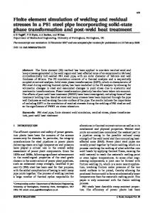
strain measurement techniques, high accuracy micrometers (least count of 1 µm) are used to measure the relative approach of the two races; that is, the deformation of balls and races combined as shown in Figure 5. The two micrometers each are placed at opposite corners of each raceway. The tests were conducted on two sets of linear bearing mock up pieces by placing different number of balls that is, two, three and four balls between the raceways under loads, varying from 200 N to 31 kN per ball. The loads were chosen in such a way that there are no indentations formed during the tests. Care was taken to ensure the following conditions during these tests: 1) The surfaces of the raceways and rolling elements were cleaned and degreased before assembly. 2) All bearing surfaces were parallel to each other and also perpendicular to the line of action of the load. 3) The balls were placed symmetrically with respect to the line of action of the load. 4) A cage was provided to restrict the balls from moving along the length of the cylindrical raceways before and during the test so that the symmetric spacing is maintained. 5) The load was applied gradually to the balls through a hydraulic Jack. The deformation of contact surfaces were evaluated by subtracting average readings of the lower raceway from the average readings of two micrometers fixed at the opposite corners of the top raceway. Due to this, the deformations in the support structure are not added with final contact deformation. Deformation at lower loads are neglected as the same are highly non-linear due to geometrical deviations in the loading structure including gaps which need to be overcome prior to establishing the ball-raceway contact. The load– deformation characteristics of various tests conducted by placing different number of balls under varying loading conditions are plotted in Figure 6. The experiments are repeated three times to ensure repeatability of the results.
RESULTS AND DISCUSSION The estimation of the load–deformation characteristics for the contact zone of the ball and raceways have been carried out using Hertz theory and FE analysis. The
Starvin et al.
133
Figure 4. Photo of linear model mock up bearing assembly.
Figure 5. Experimental set-up.
contacting bodies are made of materials defined by their 5 modulus of elasticity E(E1 = E2 = 2.06 × 10 MPa) and Poisson’s ratio μ ( 0.3) and the equivalent modulus of elasticity E* is defined in terms of properties of both
contacting materials (American National Standard ANSI/AFMA Std. 9, 1990). The initial clearance between the contacting bodies in the numerical model is made zero. The friction coefficient between the rolling element
134
Sci. Res. Essays
35000 30000
LOAD (N)
25000 20000 15000 10000
Four Ball
5000
Three Ball Two Balls
0 0
0.05
0.1
0.15
0.2
0.25
0.3
DEFORMATION (mm) Figure 6. Load–deformation characteristics.
and the raceways is taken to be 0.002. The threedimensional contact model developed and its accuracy was validated in light of favorable comparisons between finite element results and analytical solutions obtained within the elastic region. To compare these results with the experimental results, experiments were conducted on a linear angular contact mock up bearing as discussed in the previous section. The load deformation characteristics of ball-raceway combinations under varying load conditions with different number of balls are shown in Figure 6. From graph shown in Figure 6, it can be seen that the load-deformation characteristics are non-linear in nature which is as expected. Further, the differences in the deformation observed with two, three and four balls are very interesting and this needs further study. Several possible reasons exist for these differences which include the variation in the actual ball diameters and deviation in the raceway curvature along the length of the cylindrical groove, the asymmetric in loading results in non uniform load distribution etc. The comparison of the load – deformation characteristics of FE results, Hertz theory and the experimental value for four balls are shown in Figure 7. From the plot, it can be seen that all the three results closely match with each other. It is observed that homogenized four ball case very closely follows the FEM and Hertz theory compared to two and three balls case. This may be due to more uniformity and symmetry in load application in the case of four balls compared to two and three balls case. Figure 8 shows the agreement between the load and contact stresses of FEM result and Hertz theory. Figure 9 shows the variation of contact area with the applied load. The good agreement between finite
element and analytical results demonstrates the accuracy of the finite element model and appropriateness of the boundary conditions.
Implementation of FE model Proper modeling and accurate representation of rolling elements is the key factor in solving the large diameter bearings numerically. Modelling of large number of rolling elements, shape of the rolling elements and its modeling of the contact problem in a full bearing is a difficult one. Hence, by considering the complexity of modeling, it is better to apply a revolutionary approach like super element techniques to model the full bearing (Alain et al., 2008). This type of simplification allows replacing the rolling elements under compression by a non-linear spring working in tension. In the FE model, a rolling element in a sector is defined by two nodes representing the centers of curvature of race ways. Then, each node is linked to the corresponding opposite node by non-linear traction spring as shown in Figure 10. Top and bottom raceway zones of contact between the rolling element and raceway in a sector are modeled by rigid shells. Further, these rigid shells are connected to the corresponding centers of curvatures to establish elliptical contact. The super element was synthesized (non-linear spring) based on the results obtained in the ball raceway deformation characteristics and it is substituted for rolling elements in the global model as shown in Figure 11. The FE analysis shows a uniform load distribution on the 2 m model bearing (Figure 11). From Figure 12, it is clear that the loads are equally distributed on all the
Starvin et al.
135
35000 30000
Load (N)
25000 20000 15000
Hertz FEM Experimental
10000 5000 0 0
0.05
0.1
0.15
0.2
δ Deformation (mm) Figure 7. Comparison of load-deformation characteristics.
Load Vs Contact Pressure
3000 2500 2000 1500 (MPa)
Contact Pressure (MPa)
3500
HERTZ
1000
FEM
500 0 0
5000
10000
15000
20000
25000
30000
35000
Load (N) Figure 8. Plot between load and contact stress.
rolling elements of the bearing for the applied uniform load. This implies that the simplified model validates the actual bearing model and it can be used for further analysis.
CONCLUSION The non-linear
load-deformation
characteristics
of
angular contact bearing were determined using FE Models. The FE results were validated by conducting experiments on a linear contact mock up bearing fabricated at IGCAR, Kalpakkam. The results of FE experiments are compared with the Hertz relation. The results show a good agreement between them. The other contact parameters such as contact area and contact pressure measured using FEA are in good agreement with analytical results. The study of load–deformation
136
Sci. Res. Essays
20 18 16 14 12 10 8 6 4 2 0
mm)
Contact area (sq mm)
Load Vs Contact Area
Hertz FEA at Top race FEA at outer race
0
5000
10000
15000
20000
25000
30000
35000
Load (N) Figure 9. Graph between load and contact area.
Figure 10. Geometrical approach.
characteristics of a single ball with the raceways can be used as a basis to model a full bearing by sub structuring technique. The key element for the sub structuring
technique is the replacement of the rolling elements by non linear traction springs. The characteristics of the springs can be defined by the load-deformation
Starvin et al.
137
No. of Rolling Elements: 70 Dia of Rolling Element: 31.75 mm
Figure 11. FE model of 2 m slewing ring bearing.
25000
Contact Load (N)
20000
15000
10000
5000
0 0
5
10
15
20
25
30
35
40
Ball Num ber
Figure 12. Uniform contact load distribution under axial loading.
characteristics derived from the Numerical/Experimental method. This type of simplification allows for avoiding the multiple modeling of the contact problems in large diameter bearings. ACKNOWLEDGEMENT The authors thank BRNS, Mumbai which provided financial support for carrying out this research work at Structural Mechanics Laboratory at IGCAR, Kalpakkam, India. REFERENCES Abramovitz M, Stegun I (1972). Handbook of mathematical functions with formulas, graphs, and mathematical tables. Dover Publications New York. eds.
American National Standard ANSI/AFMA Std 9-1990. Load Ratings and Fatigue Life for Ball Bearings. Alain D, Zouhair C, Antoine G (2008). 3D Simplified finite elements analysis of load and contact angle in a slewing ball bearing. ASME J. Mech. Des. 130:082601-1-8. Gibezyńska T, Marciniec A (1995). Influences des parameters geometriques de la couronne d’orientation sur les efforts de conact, In:IASTED International Conference Modelling, Indentification,Control,Igls pp. 85-88. Harris TA, Kotzalas MN (2007). Essential concepts of bearing technology. Taylor & Francis. New York pp. 174-175. Hirania H (2009). Root cause failure analysis of outer ring fracture of four-row cylindrical roller bearing. Tribol. Trans. 52(2):180-190. Houpert L (2001). An Engineering Approach to Hertzian Contact Elasticity - Part 1. ASME J. Tribol. 123(3):582-588. Josu A, Mikel A, Rafael A, Igor FB (2012). Theoretical calculation of general static load-carrying capacity for the design and selection of three row roller slewing bearings. Mechanism Mach. Theory 48:5261. Ludwik K (2006). Modelling of rollers in calculation of slewing bearing with the use of finite elements. Mechanism and Machine theory.
138
Sci. Res. Essays
41:1359–1376. Pallini RA, Sague JE (1985). Computing core-yield limits for casehardened rolling bearings. ASLE Trans. 28(1):91–96. Pallini R, Rumbarger J (1979). Failure Analysis and Redesign of Large diameter stacker Reclaimer Slew Bearing. Lubr. Eng. 12:692-697. Prebil I, Zupan S, Lučič P (1995). Lastverteilung auf Wälzkörper der Drehverbindungen Konstruktion. 47(11):339–345. Qin Y, Balendra R (2000). A method for the simulation of temperature stabilization during multi-cycle cold forging operations. Int. J. Mater. Process. Technol. 107(1–3):252–259. Sague JE (1978). The special way big bearings can fail. Mach. Des. 21:113–120.
Thomas HR, Hoersch VA (1990). Stresses due to the pressure of one elastic solid upon another. University of Illinois Bulletin 212. Whittemore HL, Petrenko SN (1921). Friction and carrying capacity of ball and roller bearings. No.201, Technologic Papers of the Bureau of Standards, Washington. Zaretsky EV (1992). STLE life factors for rolling bearings, chapter 4 – Bearing Load. Illinois. STLE Publications. Zupan S, Prebil I (2001). Carrying angle and carrying capacity of a large single row ball bearing as a function of geometry parameters of rolling contact and supporting structure stiffness. Mech. Mach. Theory 36(10):1087–1103.