Technical Report
Finite Elements Q1-Lagrange for the Linear Elasticity Problem J. Figueiredo (∗) - J. M. Viaño (∗∗) (∗)
(∗∗)
Officina Mathematica. Universidade do Minho. Portugal. em.
[email protected]
Departamento de Matemática Aplicada. Universidade de Santiago de Compostela. Spain. em.
[email protected]
December 2005
2
Contents
1 The continuous problem 1.1 Classical formulation . . . . . . . . . . . . . . . . . . . . . . . . . . . . . . . . . . . . . 1.2 Variational formulation . . . . . . . . . . . . . . . . . . . . . . . . . . . . . . . . . . . 2 The 2.1 2.2 2.3 2.4 2.5
2.6
2.7
approximate problem Q1 -quadrilaterals . . . . . . . . . . . . . . . . . . . . . . . . . . . . . . . . Global formulation . . . . . . . . . . . . . . . . . . . . . . . . . . . . . . . Local formulation . . . . . . . . . . . . . . . . . . . . . . . . . . . . . . . . Formulation using the global degrees of freedom . . . . . . . . . . . . . . . Some implementation considerations and algorithms . . . . . . . . . . . . 2.5.1 Main steps . . . . . . . . . . . . . . . . . . . . . . . . . . . . . . . 2.5.2 Representation of geometrical data for the triangulation . . . . . . 2.5.3 Assembly of the rigidity matrix . . . . . . . . . . . . . . . . . . . . 2.5.4 Assembly of the second member vector . . . . . . . . . . . . . . . . 2.5.5 Rigidity matrix bandwidth and profile . . . . . . . . . . . . . . . . Computation of elementary rigidity matrices and second member vectors . 2.6.1 Change of variable to the reference square Tb . . . . . . . . . . . . 2.6.2 Elementary calculations . . . . . . . . . . . . . . . . . . . . . . . . Postprocessing calculations . . . . . . . . . . . . . . . . . . . . . . . . . . 2.7.1 Computation of main stresses and von Mises stress . . . . . . . . . 2.7.2 Computation of ku − uh k0,Ω . . . . . . . . . . . . . . . . . . . . . .
3 Tests and results 3.1 Test problem 1 - Homogeneous square plate; solution ∈ (Q1 )2 . . 3.1.1 Problem description . . . . . . . . . . . . . . . . . . . . . 3.1.2 Results . . . . . . . . . . . . . . . . . . . . . . . . . . . . 3.2 Test problem 2 - Homogeneous square plate; solution ∈ / (Q1 )2 . . 3.2.1 Problem description . . . . . . . . . . . . . . . . . . . . . 3.2.2 Results . . . . . . . . . . . . . . . . . . . . . . . . . . . . 3.3 Test problem 3 - Homogeneous triangular plate; solution ∈ (Q1 )2 3.3.1 Problem description . . . . . . . . . . . . . . . . . . . . . 3.3.2 Results . . . . . . . . . . . . . . . . . . . . . . . . . . . . 3.4 Test problem 4 - Homogeneous triangular plate; solution ∈ / (Q1 )2 3.4.1 Problem description . . . . . . . . . . . . . . . . . . . . . 3.4.2 Results . . . . . . . . . . . . . . . . . . . . . . . . . . . . 3.5 Test problem 5 - Non homogeneous plate; solution ∈ / (Q1 )2 . . . 3.5.1 Problem description . . . . . . . . . . . . . . . . . . . . . 3.5.2 Results . . . . . . . . . . . . . . . . . . . . . . . . . . . . 3.6 Test problem 6 - 2D wrench . . . . . . . . . . . . . . . . . . . . . 3.6.1 Problem description . . . . . . . . . . . . . . . . . . . . . 3.6.2 Results . . . . . . . . . . . . . . . . . . . . . . . . . . . . 3
. . . . . . . . . . . . . . . . . .
. . . . . . . . . . . . . . . . . .
. . . . . . . . . . . . . . . . . .
. . . . . . . . . . . . . . . . . .
. . . . . . . . . . . . . . . . . .
. . . . . . . . . . . . . . . .
. . . . . . . . . . . . . . . . . .
. . . . . . . . . . . . . . . .
. . . . . . . . . . . . . . . . . .
. . . . . . . . . . . . . . . .
. . . . . . . . . . . . . . . . . .
. . . . . . . . . . . . . . . .
. . . . . . . . . . . . . . . . . .
. . . . . . . . . . . . . . . .
. . . . . . . . . . . . . . . . . .
. . . . . . . . . . . . . . . .
. . . . . . . . . . . . . . . . . .
5 5 5
. . . . . . . . . . . . . . . .
10 10 11 14 17 20 20 21 22 23 24 25 25 28 32 32 34
. . . . . . . . . . . . . . . . . .
35 35 35 37 40 40 40 43 43 44 47 47 48 50 50 52 54 54 55
4 A Files used for GiD interfacing A.1 Configuration files . . . . . . . . . . . . . . . A.1.1 Conditions file (.cnd) . . . . . . . . . . A.1.2 Materials file (.mat) . . . . . . . . . . A.1.3 Problem and intervals data file (.prb) A.1.4 Template file (.bas) . . . . . . . . . . . A.2 Input and output files . . . . . . . . . . . . . A.2.1 Calculation (input) file . . . . . . . . . A.2.2 Postprocess files . . . . . . . . . . . .
. . . . . . . .
. . . . . . . .
. . . . . . . .
. . . . . . . .
. . . . . . . .
. . . . . . . .
. . . . . . . .
. . . . . . . .
. . . . . . . .
. . . . . . . .
. . . . . . . .
. . . . . . . .
. . . . . . . .
. . . . . . . .
. . . . . . . .
. . . . . . . .
. . . . . . . .
. . . . . . . .
. . . . . . . .
. . . . . . . .
. . . . . . . .
. . . . . . . .
. . . . . . . .
61 61 61 62 63 63 65 65 67
1. The continuous problem 1.1. Classical formulation Let Ω be an open bounded connected set of R2 with piecewise C 1 boundary Γ. Let Γ1 be a part of Γ having strictly positive measure and Γ2 = Γ − Γ1 . We denote by x = (x1 , x2 ) a generic point of Ω = Ω ∪ Γ. For x ∈ Γ2 , we denote by ν (x) = (ν 1 (x) , ν 2 (x)) the outward unit vector normal to Γ2 at the point x. If v = (v1 , v2 ) is a function defined on Ω taking values in R2 , we consider µ ¶ ∂vj 1 ∂vi , 1 ≤ i, j ≤ 2, (1.1) + εij (v) = 2 ∂xj ∂xi and σ ij (v) = λ
à 2 X
!
εkk (v) δ ij + 2µεij (v),
k=1
1 ≤ i, j ≤ 2,
(1.2)
where δ ij denotes the Kronecker’s symbol and λ and µ are constants such that λ ≥ 0,
µ > 0.
Let us consider the following problem: given functions f = (f1 , f2 ) : Ω → R2
g = (g1 , g2 ) : Γ2 → R2 ,
and
find a function u = (u1 , u2 ) solution of −
2 X ∂ σ ij (u) = fi ∂xj
in Ω,
1 ≤ i ≤ 2,
(1.3a)
ui = 0 on Γ1 ,
1 ≤ i ≤ 2,
(1.3b)
1 ≤ i ≤ 2.
(1.3c)
j=1
2 X
σ ij (u) ν j = gi
on Γ2 ,
j=1
The problem (1.3) describes the displacement field u with respect to the natural state of an elastic homogeneous isotropic solid subject to a density force f in Ω and a density force g on Γ2 - see e.g. Raviart and Thomas (1998). The displacements u are imposed null over Γ1 . The coefficients λ and µ are the so-called Lamé’s constants for the material occupying Ω and relate the coefficients σ ij of the stress tensor to the coefficients εij of the linearized strain tensor as given by (1.2).
1.2. Variational formulation We use the standard notation for the classical spaces L2 (Ω) and H 1 (Ω) (Sobolev space of order 1), see e.g. Adams (1975). £ ¤2 We denote by (·, ·)0 the inner product on L2 (Ω) and L2 (Ω) , that is Z ξζ dx, ξ, ζ ∈ L2 (Ω) (ξ, ζ)0 = Ω
(u, v)0 =
2 X
(ui , vi )0 ,
i=1
5
£ ¤2 u, v ∈ L2 (Ω) ,
6
1.2. Variational formulation
where u = (u1 , u2 ) and v = (v1 , v2 ). The norms induced by these inner products will be denoted by k·k0 : 1/2
ξ ∈ L2 (Ω) , Ã 2 ! 12 X = kvi k20 ,
kξk0 = (ξ, ξ)0 , 1/2
kvk0 = (v, v)0
i=1
£ ¤2 v ∈ L2 (Ω) .
£ ¤2 We further denote by (·, ·)1 the inner product on H 1 (Ω) and H 1 (Ω) , that is (ξ, ζ)1
¶ 2 µ X ∂ξ ∂ζ = (ξ, ζ)0 + , , ∂xi ∂xi 0 i=1
(u, v)1 =
2 X
(ui , vi )1 ,
i=1
and by k·k1 the corresponding induced norms: 1/2
kξk1 = (ξ, ξ)1 , kvk1 =
1/2 (v, v)1
=
à 2 X i=1
kvi k21
! 12
.
The following results are not trivial - see e.g. Duvaut and Lions (1972), Adams (1975): Theorem 1. (Korn’s inequality) Let Ω be an open bounded connected set of R2 with piecewise C 1 boundary Γ and Γ1 a part of Γ such that meas(Γ1 ) 6= 0. Then, there exists a constant C > 0 such that 2 X £ ¤2 kεij (v)k20,Ω ≥ C (Ω, Γ1 ) kvk21,Ω , ∀v ∈ H 1 (Ω) , i,j=1
such that v = 0 on Γ1 . Theorem 2. (Trace theorem) Let Ω be an open bounded connected set of R2 with piecewise C 1 boundary Γ. Then (i) there exists a unique bounded linear operator γ γ : H 1 (Ω) → L2 (Γ) ,
¡ ¢ with the property that if ξ ∈ C 1 Ω , then γ (ξ) = ξ|Γ in the conventional sense;
(ii) the range of γ is dense in L2 (Γ).
We also recall the Green’s formula: Z Z Z ∂ξ ∂ζ ζ dx = − ξ dx + ξζ ν i dγ, ∂xi ∂xi Ω
Ω
∀ξ, ζ ∈ H 1 (Ω) ,
i = 1, 2,
Γ
where dγ denotes the one-dimensional measure of Γ. £ ¤2 £ ¤2 We assume that f = (f1 , f2 ) ∈ L2 (Ω) and g = (g1 , g2 ) ∈ L2 (Γ2 ) , and consider the space of admissible displacements o n £ ¤2 (1.4) V = v = (v1 , v2 ) ∈ H 1 (Ω) : (v1 , v2 ) = (0, 0) on Γ1 .
1. The continuous problem
7
Then, if u is a solution of problem (1.3) smooth enough to belong to V , we have u∈V: Z 2 P − Ω
∂ σ ij (u) vi dx = i,j=1 ∂xj
Z
Ω
2 P
fi vi dx,
∀v = (v1 , v2 ) ∈ V.
i=1
Invoking Green’s formula, we obtain u∈V: Z 2 P Ω
i,j=1
σ ij (u) εij (v) dx −
Z
Γ2
2 P
Z
σ ij (u) ν j vi dγ =
i,j=1
Ω
2 P
fi vi dx,
i=1
∀v = (v1 , v2 ) ∈ V. Taking into account the condition (1.3c) involving the forces acting on Γ2 , then u is a solution of the variational problem Find u ∈ V such that: Z 2 Z 2 Z 2 P P P σ ij (u) εij (v) dx = fi vi dx + gi vi dγ, Ω
i,j=1
Ω
i=1
Γ2
i=1
∀v = (v1 , v2 ) ∈ V. Using the relation between the components of the stress tensor σ and those of the strain tensor ε (cf. (1.2)), then an equivalent form for the problem is Find u ∈ V such that: ¶ ¾ Z 2 ½ µ 2 Z 2 Z 2 P P P P λ εkk (u) δ ij + 2µεij (u) εij (v) dx = fi vi dx + gi vi dγ, Ω
i,j=1
k=1
Ω
i=1
Γ2
i=1
∀v = (v1 , v2 ) ∈ V, or Find u ∈ V such that: Z Z Z 2 Z 2 2 P P P λ div u div v dx + 2µ εij (u) εij (v) dx = fi vi dx + gi vi dγ, Ω
Ω
i,j=1
Ω
i=1
Γ2
i=1
∀v = (v1 , v2 ) ∈ V. Defining the bilinear form a : V × V → R: a(u, v) =
Z X 2
σ ij (u) εij (v) dx =
Ω i,j=1
Z
λ div u div v dx +
Ω
and the linear form l : V → R: l (v) =
Z X 2
fi vi dx +
Ω i=1
Z
2µ
Ω
Z X 2
2 X
εij (u) εij (v) dx
(1.5)
i,j=1
gi vi dγ,
(1.6)
Γ2 i=1
the variational continuous problem is written as Find u ∈ V such that: a(u, v) = l(v), ∀v ∈ V.
(1.7)
In order to prove the existence and uniqueness of solution of problem (1.7) we recall the Lax-Milgram’s lemma:
8
1.2. Variational formulation
Theorem 3. (Lax-Milgram lemma): Let V be a real Hilbert space with norm k·k, a : V × V → R a bilinear form and l : V → R a linear form verifying: (i) a is continuous on V : |a(u, v)| ≤ M kuk kvk , (ii) a is V -elliptic: a(v, v) ≥ α kvk2 ,
∀v ∈ V,
(iii) l is continuous on V : |l(v)| ≤ C kuk ,
∀u, v ∈ V,
M > 0;
α > 0;
∀v ∈ V,
C > 0.
Then there exists and unique element u satisfying: u ∈ V,
a (u, v) = l(v),
∀v ∈ V.
£ ¤2 Since the space V defined by (1.4) is an Hilbert space (subspace of the Hilbert space H 1 (Ω) ), in order to prove the existence and uniqueness of solution of problem (1.7) we only need to prove that the hypotheses of the Lax-Milgram’s lemma hold. We first show that the linear form defined by (1.6) is continuous on V . Let v ∈ V be an arbitrary element of V . Then ¯ ¯ ¯ ¯Z X Z X 2 2 ¯ ¯ fi vi dx + gi vi dγ ¯¯ |l (v)| = ¯¯ ¯ ¯ i=1 i=1 Ω
Γ2
¯ ¯ ¯ ¯ ¯Z X ¯ ¯Z X ¯ 2 2 ¯ ¯ ¯ ¯ ¯ ¯ ¯ ≤ ¯ fi vi dx¯ + ¯ gi vi dγ ¯¯ ¯ i=1 ¯ ¯ i=1 ¯ Ω
Γ2
= |(f, v)0,Ω | + |(g, v)0,Γ2 |
≤ kf k0,Ω kvk0,Ω + kgk0,Γ2 kvk0,Γ2 ≤ kf k0,Ω kvk1,Ω + C kgk0,Γ2 kvk1,Ω , ³ ´ ≤ kvk1,Ω kf k0,Ω + C kgk0,Γ2 ,
C > 0,
where we have used the Cauchy-Schwarz inequality and the continuity of the trace operator. To show that the bilinear form a is continuous on V , we use the Cauchy-Schwarz inequality and write: ¯ ¯ ¯Z ¯ Z X 2 ¯ ¯ ¯ |a(u, v)| = ¯ λ div u div v dx + 2µ εij (u) εij (v) dx¯¯ ¯ ¯ Ω Ω i,j=1 ¯ ¯ ¯ ¯ ¯Z X ¯Z ¯ ¯ 2 ¯ ¯ ¯ ¯ ¯ ¯ ¯ ≤ λ ¯ div u div v dx¯ + 2µ ¯ εij (u) εij (v) dx¯¯ ¯ i,j=1 ¯ ¯ ¯ Ω
Ω
≤ λ |(div u, div v)0,Ω | + 2µ
2 X
i,j=1
≤ λ kdiv uk0,Ω kdiv vk0,Ω + 2µ
|(εij (u), εij (v))0,Ω |
2 X
i,j=1
kεij (u)k0,Ω kεij (v)k0,Ω .
Given that all the norms in the above expression are L2 (Ω)-norms of various combinations of first derivatives of u and v it follows that there is a constant M > 0 such that |a(u, v)| ≤ M kuk1,Ω kvk1,Ω
1. The continuous problem
9
as required. To prove the V -ellipticity of the bilinear form a we consider a(v, v) =
Z
2
λ (div v) dx + 2µ
Ω i,j=1
Ω
≥ 2µ
Z X 2
2 X
i,j=1
kεij (v)k20,Ω .
Invoking the Korn’s inequality, we obtain a(v, v) ≥ α kvk2V as required.
[εij (v)]2 dx
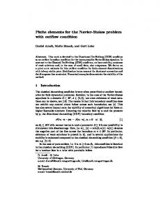
2. The approximate problem 2.1. Q1 -quadrilaterals b1 , Σ), b where Tb is the reference square Tb = [0, 1]×[0, 1] Let us consider the reference finite element (Tb, Q b1 denotes a space of b and Σ = {b ai , i = 1, 2, 3, 4} is the set of vertices of Tb as shown in Figure 2.1. Q b2 of degree less than or equal to 1 in each variable: polynomials defined on Tb with variables x b1 , x b 1 = h1, x b1 , x b2 , x b1 x b2 i . Q
Given 4 points a1 , a2 , a3 , a4 ∈ R2 we denote by T the convex hull of a1 , a2 , a3 , a4 . Assuming that T is not degenerated and denoting the set of vertices of T by ΣT = {aTi , i = 1, 2, 3, 4}, it can be shown that there is a unique invertible map FT : Tb → R2 such that µ ¶ ³ ´ 2 (FT )1 b1 , FT = ∈ Q (FT )2 with the property
ai ), T = FT (Tb) and aTi = FT (b
i = 1, ..., 4
(see Figure 2.2). Under these conditions we can define the “Q1 -finite element” (T, PT , ΣT ) induced by the map FT , where n o b1 . PT = p : T → R : pb = p ◦ FT ∈ Q (2.1)
b1 having the property b 1 = 4, taking {b p1 , pb2 , pb3 , pb4 } as a base of Q Since dim Q (see § 2.6), leads to
aj ) = δ ij , pbi (b
x) = FT (b
4 X ¡ i=1
1 ≤ i, j ≤ 4,
³ ´2 ¢ b1 . aTi pbi (b x) ∈ Q
Figure 2.1: The reference element Tb
x), we get Furthermore, considering the definition of the space PT (2.1) and taking x = FT (b ¢ ¡ x) = pTi (x) , 1 ≤ i ≤ 4, x) = pTi ◦ FT (b pbi (b 10
(2.2)
2. The approximate problem
11
Figure 2.2: Quadrilateral element T and the corresponding map FT or, alternatively, pTi (x) = pbi ◦ FT−1 (x) ,
1 ≤ i ≤ 4.
It can be shown that under these conditions p ∈ PT
⇒
b1 ⊂ Pb2 ∧ p ◦ FT | e ∈ Pb1 , p ◦ FT ∈ Q ∂ Tl
where Pbi stands for the space of polynomials of degree i in each variable defined on Tb = [0, 1]2 , while ∂ Tbl is the side l of the reference square Tb, with 1 ≤ l ≤ 4.
2.2. Global formulation
Let Th be a triangulation of Ω of finite elements type, compatible with the partition Γ = Γ1 ∪ Γ2 , made of quadrilaterals, that is: (i) Ω = ◦
S
T ∈Th
T, where T is a non-degenerated quadrilateral;
◦
(ii) T 1 ∩ T 2 = ∅, ∀T1 , T2 ∈ Th , T1 6= T2 ; (iii) T1 ∩ T2 = ∅, or T1 ∩ T2 = shared corner, or T1 ∩ T2 = shared edge, ∀T1 , T2 ∈ Th , T1 6= T2 ; (iv) T ∩ Γi = ∅, or T ∩ Γi = corner of T , or T ∩ Γi = edge of T , for i = 1, 2, ∀T ∈ Th ; and consider hT = diam(T ) = max {|x − y|} , x,y∈T
T ∈ Th ,
h = max hT , T ∈Th
where |z| =
µ
n P
i=1
zi2
¶1/2
denotes the Euclidean norm in Rn .
We now define the space of finite elements, Xh , as Xh = X1h × X2h , where
© ¡ ¢ ª X1h = X2h = vh ∈ C 0 Ω : vh |T ∈ PT , ∀T ∈ Th .
The space of admissible displacements, Vh ⊂ V , is defined by
Vh = {vh ∈ Xh : vh = 0 on Γ1 } .
(2.3)
12
2.2. Global formulation
Therefore, the approximate counterpart of the continuous variational problem (1.7) is Find uh = (u1h , u2h ) ∈ Vh such that: a(uh , vh ) = l(vh ), ∀vh = (v1h , v2h ) ∈ Vh ,
(2.4)
with (cf. (1.5) and (1.6)) a(uh , vh ) =
Z
λ div uh div vh dx +
Ω
l(vh ) =
Z
Ω
Z X 2
fi vih dx +
Ω i=1
Z X 2
2µ
2 X
εij (uh ) εij (vh ) dx,
i,j=1
gi vih dγ.
Γ2 i=1
Let Σh be the set of nodes forming the triangulation (see Figure 2.3), that is, [ Σh = ΣT = {ai : 1 ≤ i ≤ N } . T ∈Th
Figure 2.3: Triangulation nodes Since every function vih of Xih (i = 1, 2) is univocally determined by the degrees of freedom vih (a1 ), vih (a2 ), ..., vih (aN ), the dimension of Xih is N. The (global) basis functions of Xih are the N functions {wk : 1 ≤ k ≤ N } satisfying wk ∈ Xih ,
wk (aj ) = δ kj ,
i = 1, 2,
1 ≤ k, j ≤ N.
Therefore, every function vih of Xih has a unique representation vih =
N X
vih (aj ) wj .
j=1
We now introduce the vector of the global degrees of freedom ve: ⎞ ⎛ v1h (a1 ) ⎜ v2h (a1 ) ⎟ ⎟ ⎜ ⎟ ⎜ .. ve = ⎜ ⎟ , ve ∈ R2N , vih ∈ Xih , i = 1, 2, . ⎟ ⎜ ⎝ v1h (aN ) ⎠ v2h (aN )
that is,
(
ve2j−1 = v1h (aj ) ve2j = v2h (aj )
,
1 ≤ j ≤ N.
(2.5)
2. The approximate problem
13
Since {(wj , 0) , 1 ≤ j ≤ N } and {(0, wj ) , 1 ≤ j ≤ N} are bases of the spaces X1h and X2h , respectively, we write N N X X ve2j−1 (wj , 0) + ve2j (0, wj ) . vh = (v1h , v2h ) = j=1
j=1
Then, the bilinear form a can be written as ⎛ ⎞ N N N N X X X X u e2i−1 (wi , 0) + u e2i (0, wi ) , ve2j−1 (wj , 0) + ve2j (0, wj )⎠ a (uh , vh ) = a ⎝ i=1
=
N X
i,j=1
+
j=1
ve2j−1 a ((wj , 0) , (wi , 0)) u e2i−1 + N X
i,j=1
leading to
i=1
j=1
N X
ve2j a ((0, wj ) , (wi , 0)) u e2i−1 +
i,j=1
ve2j−1 a ((wj , 0) , (0, wi )) u e2i +
N X
i,j=1
ve2j a ((0, wj ) , (0, wi )) u e2i ,
e, a (uh , vh ) = ve t A u
(2.6)
where A is a matrix of order 2N with the following structure: ⎛ a ((w1 , 0) , (w1 , 0)) a ((w1 , 0) , (0, w1 )) · · · ⎜ a ((0, w ) , (w , 0)) a ((0, w ) , (0, w )) · · · 1 1 1 1 ⎜ A=⎜ .. .. .. ⎜ ⎝ . . .
a ((0, wN ) , (w1 , 0)) a ((0, wN ) , (0, w1 )) · · ·
Since the bilinear form a is symmetric, we have ⎧ A2i−1,2j−1 = a ((wi , 0) , (wj , 0)) ⎪ ⎪ ⎪ ⎪ ⎪ ⎨ A2i−1,2j = a ((wi , 0) , (0, wj )) ⎪ A2i,2j−1 = a ((0, wi ) , (wj , 0)) ⎪ ⎪ ⎪ ⎪ ⎩ A2i,2j = a ((0, wi ) , (0, wj ))
,
a ((w1 , 0) , (0, wN )) a ((0, w1 ) , (0, wN )) .. . a ((0, wN ) , (0, wN ))
⎞
⎟ ⎟ ⎟. ⎟ ⎠
1 ≤ i, j ≤ N.
(2.7)
(2.8)
In a similar way, we obtain for the linear functional l:
l (vh ) = ve t b,
where b ∈ R2N is given by
that is
⎛
(
l ((w1 , 0))
⎜ ⎜ l ((0, w1 )) ⎜ ⎜ .. b=⎜ . ⎜ ⎜ ⎝ l ((wN , 0)) l ((0, wN )) b2i−1 = l ((wi , 0)) b2i = l ((0, wi ))
,
(2.9) ⎞
⎟ ⎟ ⎟ ⎟ ⎟, ⎟ ⎟ ⎠ 1 ≤ i ≤ N.
Supposing that nodes ali , i = 1, . . . , S, belong to Γ1 , then the members of Vh are such that v1h (ali ) = v2h (ali ) = 0,
i = 1, . . . , S,
or, equivalently, ve2li −1 = ve2li = 0,
i = 1, . . . , S.
(2.10)
14
2.3. Local formulation
Hence, inserting (2.6) and (2.9) into (2.4), we conclude that the approximate problem corresponding to the continuous problem (1.7) is Find u e ∈ R2N , with u e2li −1 = u e2li = 0, i = 1, . . . , S, satisfying:
ve t A u e = ve t b
(2.11)
∀e v ∈ R2N , such that ve2li −1 = ve2li = 0, i = 1, . . . , S.
2.3. Local formulation
Let T ∈ Th be an arbitrary element of the triangulation. Since we are using Lagrange Q1 elements and Q1 = h1, x1 , x2 , x1 x2 i ⇒ dim Q1 = 4, each (quadrilateral) element T will have 4 nodes © ª ΣT = aT1 , aT2 , aT3 , aT4 ,
that coincide with the 4 vertices of the element. We also consider pTi ∈ PT ,
1 ≤ i ≤ 4,
the ith base polynomial of element T (T, PT , ΣT ), and impose (cf. (2.5)) ¡ ¢ pTi aTj = δ ij , 1 ≤ i, j ≤ 4.
(2.12)
Now, let vih be an arbitrary member of the finite element space Xih (i = 1, 2). We have vih |T ∈ PT by definition (2.3), so that ¡ ¢ ⎞ ⎛ vih aT1 ¡ T¢ ⎟ 4 X ¡ T¢ T ¡ T ¢⎜ ⎜ vih ¡a2 ¢ ⎟ T T T vih |T = vih ak pk = p1 p2 p3 p4 ⎜ ⎟ ⎝ vih aT3 ⎠ k=1 ¡ ¢ vih aT4
for 1 ≤ i ≤ 2. We also have
à 4 ! ¯ ³ X ¡ T ¢ ∂pTk ∂vih ¯¯ a = v = ih k ∂xj ¯T ∂xj
∂pT 1 ∂xj
k=1
∂pT 2 ∂xj
∂pT 3 ∂xj
∂pT 4 ∂xj
⎛
´⎜ ⎜ ⎜ ⎝
¡ ¢ vih aT1 ¡ ¢ vih aT2 ¡ ¢ vih aT3 ¡ ¢ vih aT4
⎞ ⎟ ⎟ ⎟ ⎠
for 1 ≤ i, j ≤ 2. Therefore, defining the vector of local degrees of freedom, vT ∈ R8 ,
£ ¡ ¢ ¡ ¢ ¡ ¢ ¡ ¢ ¡ ¢ ¡ ¢ ¡ ¢ ¡ ¢¤t vT = v1h aT1 , v1h aT2 , v1h aT3 , v1h aT4 , v2h aT1 , v2h aT2 , v2h aT3 , v2h aT4 ,
we may write, on the one hand,
Ã
v1h v2h
where Ã
pT1
pT2
!¯ ¯ £ ¤ ¯ ¯ = P T vT ¯
(2.13)
T
pT3
pT4
0
0
0
0 0 0 0 pT1 pT2 µ £ T¤ ¶ P £ 0T ¤ ∈ M2×8 , = 0 P
pT3
pT4
£ T¤ P =
0
! (2.14)
2. The approximate problem with
and, on the other hand,
15
£ T¤ ¡ T P = p1 ⎛ ⎜ ⎜ ⎜ ⎜ ⎜ ⎜ ⎜ ⎝
∂v1h ∂x1 ∂v1h ∂x2 ∂v2h ∂x1 ∂v2h ∂x2
where ⎛
∂pT 1 ∂x1
⎜ ⎜ T ⎜ ∂p1 ⎜ ∂x £ ¤ ⎜ 2 DP T = ⎜ ⎜ ⎜ 0 ⎜ ⎝ 0
with
pT2
pT3
pT4
¢
∈ M1×4,
⎞¯ ¯ ¯ ⎟¯ ⎟¯ ⎟¯ ¤ £ ⎟¯ ⎟¯ = DP T vT , ⎟¯ ⎟¯ ⎠¯ ¯ ¯
(2.15)
T
∂pT 2 ∂x1
∂pT 3 ∂x1
∂pT 4 ∂x1
0
0
0
∂pT 2 ∂x2
∂pT 3 ∂x2
∂pT 4 ∂x2
0
0
0
0
0
0
∂pT 1 ∂x1
∂pT 2 ∂x1
∂pT 3 ∂x1
0
0
0
∂pT 1 ∂x2
∂pT 2 ∂x2
∂pT 3 ∂x2
¤ µ £ ¶ DP T £ 0 ¤ = ∈ M4×8 , 0 DP T ⎛
£ ¤ ⎜ DP T = ⎝
∂pT 1 ∂x1
∂pT 2 ∂x1
∂pT 3 ∂x1
∂pT 4 ∂x1
∂pT 1
∂pT 2
∂pT 3
∂pT 4
∂x2
∂x2
∂x2
∂x2
0
⎞
⎟ ⎟ ⎟ 0 ⎟ ⎟ ⎟ ⎟ ∂pT 4 ⎟ ∂x1 ⎟ ⎠ T ∂p4 ∂x2
(2.16)
⎞
⎟ ⎠ ∈ M2×4 .
At this stage, it is useful to consider the strain vector {ε} and the stress vector {σ}, which are defined using the entries of the corresponding (symmetric) tensors. For the strain vector {ε} we have (cf. (1.1))
{ε (vh )}|T
=
⎛ ⎧ ⎫¯ ⎨ ε11 (vh ) ⎬¯¯ ⎜ ¯ =⎜ ε22 (vh ) ⎜ ⎩ ⎭¯¯ ⎝ 2ε12 (vh ) T
⎧ ⎪ ⎪ ⎪ ⎛ ⎞⎪ ⎪ ⎪ 1 0 0 0 ⎨ ⎝ ⎠ = 0 0 0 1 ⎪ ⎪ 0 1 1 0 ⎪ ⎪ ⎪ ⎪ ⎩
where (2.15) has been used, and
∂v1h ∂x1 ∂v1h ∂x2 ∂v2h ∂x1 ∂v2h ∂x2
£ ¤ = [D] DP T vT , ⎛
∂v1h ∂x1 ∂v2h ∂x2 ∂v1h ∂v2h ∂x2 + ∂x1
⎞ 1 0 0 0 [D] = ⎝ 0 0 0 1 ⎠ . 0 1 1 0
⎫¯ ¯ ⎪ ¯ ⎪ ⎪ ¯ ⎪ ⎪ ⎪ ⎬¯¯ ¯ ¯ ⎪ ¯ ⎪ ⎪ ¯ ⎪ ⎪ ⎪ ⎭¯¯
⎞ ⎟ ⎟ ⎟ ⎠
T
(2.17)
16
2.3. Local formulation
The stress vector {σ} is defined by (cf. (1.2)) ⎧ ⎫¯ ⎞¯ ⎛ λ (ε11 + ε22 ) + 2µε11 ¯¯ ⎨ σ 11 (vh ) ⎬¯¯ {σ (vh )}|T = σ (v ) ¯ = ⎝ λ (ε11 + ε22 ) + 2µε22 ⎠¯¯ ⎩ 22 h ⎭¯¯ ¯ 2µε12 σ 12 (vh ) T T ⎫¯ ⎛ ⎞¯ ⎧ λ + 2µ λ 0 ¯¯ ⎨ ε11 ⎬¯¯ ¯ ⎝ = ε λ λ + 2µ 0 ⎠¯¯ ⎩ 22 ⎭¯¯ ¯ 2ε12 0 0 µ T T £ T¤ = E {ε (vh )}|T £ ¤ £ ¤ = E T [D] DP T vT , with
(2.18)
⎛ ⎞¯ λ + 2µ λ 0 ¯¯ £ T¤ E =⎝ λ λ + 2µ 0 ⎠¯¯ . 0 0 µ ¯T
Thus, we can write the bilinear form (1.5) present in the approximate problem (2.4) as a (uh , vh ) =
Z X 2
σ ij (uh ) εij (vh ) dx =
Ω i,j=1
Z
{ε (vh )}t {σ (uh )} dx.
Ω
S
Taking into account that Ω = T ∈Th T, we obtain using (2.17) and (2.18) X Z X Z ¯ £ ¤t £ ¤ £ ¤ t¯ a (uh , vh ) = {ε (vh )} T {σ (uh )}|T dx = vTt DP T [D]t E T [D] DP T uT dx. T ∈Th T
T ∈Th T
Furthermore, defining
⎛
λ + 2µ ⎜ £ ¤ £ T¤ 0 E = [D]t E T [D] = ⎜ ⎝ 0 λ
we obtain
a (uh , vh ) =
X Z
T ∈Th T
⎞¯ ¯ 0 λ ¯ ⎟¯ µ 0 ⎟¯ ∈ M4×4 , ⎠¯ µ 0 ¯ 0 λ + 2µ ¯T
0 µ µ 0
£ ¤t £ ¤ £ ¤ vTt DP T E T DP T uT dx.
(2.19)
Similarly, we have for the linear functional (1.6) present in the approximate problem (2.4) ⎛ ⎞ Z X Z X Z X 2 2 2 2 X Z X ⎝ l(vh ) = fi vih dx + gi vih dγ = fi |T vih |T dx + gi |∂T vih |T dγ ⎠ , Ω i=1
Γ2 i=1
T ∈Th
T i=1
T ∩Γ2 i=1
resulting
l (vh ) =
X
T ∈Th
where
⎛ Z Z ¡ ¢¯ £ T ¤ ¯ ⎝ v1h v2h T f dx +
2 X ¡
v1h v2h
T ∩Γ2 i=1
T
£ T¤ f =
µ
f1 f2
¶¯ ¯ ¯ ¯
T
and
£ T¤ g =
£ ¤ £ ¤ with f T , g T ∈ M2×1 . Hence, using (2.13) we get ⎛ Z X Z £ ¤t £ T ¤ f dx + l (vh ) = ⎝ vTt P T T ∈Th T
T ∩Γ2
µ
vTt
g1 g2
¶¯ ¯ ¯ ¯
⎞ ¢¯ £ T ¤ ¯ g dγ ⎠ , T
, ∂T
⎞ £ T ¤t £ T ¤ P g dγ ⎠ .
(2.20)
2. The approximate problem
17
Expressions (2.19) and (2.20) allow us to write the approximate problem (2.4) as Find uh ∈ Xh such that: ⎛ Z Z X X Z £ ¤ £ ¤ £ ¤ £ ¤ £ ¤ t ⎝ v t P T t f T dx + vTt DP T E T DP T uT dx = T
T ∈Th T
T ∈Th
T
T ∩Γ2
∀vT ∈ Vh .
⎞ £ ¤ £ ¤ t vTt P T g T dγ ⎠
2.4. Formulation using the global degrees of freedom Let us consider once more the vectors of the global degrees of freedom ⎛
v1h (a1 ) v2h (a1 ) .. .
⎜ ⎜ ⎜ ve = ⎜ ⎜ ⎝ v1h (aN ) v2h (aN )
⎞
⎟ ⎟ ⎟ ⎟, ⎟ ⎠
⎛
u1h (a1 ) u2h (a1 ) .. .
⎜ ⎜ ⎜ u e=⎜ ⎜ ⎝ u1h (aN ) u2h (aN )
⎞
⎟ ⎟ ⎟ ⎟, ⎟ ⎠
u e, ve ∈ R2N ,
uih , vih ∈ Xih , i = 1, 2.
Given the fact that for an element T , having nodes aT1 , aT2 , aT3 , aT4 , we have aTα = anTα ,
1 ≤ nTα ≤ N,
1 ≤ α ≤ 4,
then there exists a matrix B T ∈ M8×2N , depending on T , such that
that is ⎛ ⎜ ⎜ ⎜ ⎜ ⎜ ⎜ ⎜ ⎜ ⎜ ⎜ ⎜ ⎜ ⎜ ⎝
¡ ¢ v1h aT1 ¡ ¢ v1h aT2 ¡ ¢ v1h aT3 ¡ ¢ v1h aT4 ¡ ¢ v2h aT1 ¡ ¢ v2h aT2 ¡ ¢ v2h aT3 ¡ ¢ v2h aT4
It can be easily shown that
⎞
£ ¤ vT = B T ve,
⎛
v1h (anT )
⎞
⎛ ⎟ v1h (anT ) ⎟ 2 ⎟ ⎜ ⎜ v1h (anT ) ⎟ ⎟ ⎜ 3 ⎟ ⎜ ⎟ v1h (anT ) ⎟ £ T ¤ ⎜ ⎜ 4 ⎟= B ⎜ ⎟ ⎜ v2h (anT ) ⎟ ⎜ 1 ⎟ ⎜ v2h (anT ) ⎟ ⎜ 2 ⎟ ⎝ v2h (anT ) ⎟ ⎠ 3 v2h (anT ) 1
⎜ ⎟ ⎜ ⎟ ⎜ ⎟ ⎜ ⎟ ⎜ ⎟ ⎜ ⎟ ⎜ ⎟ ⎜ ⎟=⎜ ⎟ ⎜ ⎟ ⎜ ⎟ ⎜ ⎟ ⎜ ⎟ ⎜ ⎠ ⎜ ⎝
4
£ T¤ B i,j = δ j,2nT −1 i
where
ζ Ti =
(
2nTi − 1 2nTi−4
⎞
v2h (a1 ) ⎟ ⎟ ⎟ v1h (a2 ) ⎟ ⎟ v2h (a2 ) ⎟ ⎟. ⎟ .. ⎟ ⎟ . ⎟ v1h (aN ) ⎠
v2h (aN )
i
with 1 ≤ i ≤ 4 and 1 ≤ j ≤ 2N . We may also write
i−4
v1h (a1 )
£ T¤ B i+4,j = δ j,2nT ,
and
⎧ ⎨ δ j,2nT −1 £ T¤ i B ij = ⎩ δ j,2nT
(2.21)
if
1 ≤ i ≤ 4,
if
5 ≤ i ≤ 8,
= δ j,ζ T ,
if
1 ≤ i ≤ 4,
if
5 ≤ i ≤ 8.
i
(2.22)
(2.23)
18
2.4. Formulation using the global degrees of freedom
For example, for the triangulation shown in Figure 2.4,
Figure 2.4: Node numbers: Global (left) and local (right) we would have for element T (N = 6): nT1 = 4,
nT2 = 5,
nT3 = 2,
nT4 = 1,
leading to ζ T = {7, 9, 3, 1, 8, 10, 4, 2} In this case B T ∈ M8×12 would be given by (cf. (2.22)) ⎛
⎜ ⎜ ⎜ ⎜ £ T¤ ⎜ B =⎜ ⎜ ⎜ ⎜ ⎜ ⎝
0 0 0 1 0 0 0 0
··· ··· 0 0 ··· ··· ··· 1
··· ··· 1 ··· ··· ··· 0 0
··· ··· 0 ··· ··· ··· 1 ···
··· ··· ··· ··· ··· ··· 0 ···
0 ··· ··· ··· ··· ··· ··· ···
1 ··· ··· ··· 0 ··· ··· ···
0 0 ··· ··· 1 ··· ··· ···
··· 1 ··· ··· 0 0 ··· ···
··· 0 ··· ··· ··· 1 ··· ···
··· ··· ··· ··· ··· 0 ··· ···
0 0 0 0 0 0 0 0
⎞
⎟ ⎟ ⎟ ⎟ ⎟ ⎟. ⎟ ⎟ ⎟ ⎟ ⎠
We are now able to write the approximate problem using the global degrees of freedom. For that we suppose that nodes ali , i = 1, . . . , S, belong to Γ1 , that is, u1h (ali ) = u2h (ali ) = 0,
i = 1, . . . , S,
or, equivalently, e2li = 0, u e2li −1 = u
i = 1, . . . , S.
Hence, the approximate problem (2.4) can be written in the form Find u e ∈ R2N , with u e2li −1 = u e2li = 0, i = 1, . . . , S, satisfying: Z X £ ¤t £ ¤t £ T ¤ £ ¤ £ ¤ ve t B T DP T E DP T B T u e dx = T ∈Th T
=
X
T ∈Th
⎛ Z Z £ ¤ £ ¤ £ ¤ ⎝ ve t B T t P T t f T dx + T
T ∩Γ2
⎞ £ ¤ £ ¤ £ ¤ t t PT g T dγ ⎠ , ve t B T
∀vh ∈ Vh , where ve = [v1h (a1 ) , v2h (a1 ) , . . . , v1h (aN ) , v2h (aN )]t ∈ R2N .
Since the mapping from vh ∈ Vh to ve ∈ R2N , such that ve2li −1 = ve2li = 0,
i = 1, . . . , S,
2. The approximate problem
19
is an isomorphism, the approximate problem (2.4) is equivalent to e2li −1 = u e2li = 0, i = 1, . . . , S, satisfying: Find u e ∈ R2N , with u ⎧ ⎫ ⎞ ⎛ Z ⎨X £ ¤ ⎬ £ £ ¤ £ ¤ £ ¤ ¤ t t BT ⎝ DP T E T DP T dx⎠ B T ve t u e= ⎩ ⎭ T ∈Th
T
⎧ ⎛ Z Z ⎨X £ ¤ £ T ¤t £ T ¤ t ⎝ t T B P f dx + = ve ⎩ T ∈Th
∀e v∈
R2N ,
T
T ∩Γ2
such that ve2li −1 = ve2li = 0, i = 1, . . . , S.
Defining the elementary rigidity matrix Z £ T¤ £ ¤t £ T ¤ £ ¤ R = DP T E DP T dx,
⎞⎫ ⎬ £ T ¤t £ T ¤ P g dγ ⎠ , ⎭
RT ∈ M8×8 ,
(2.24)
T
and the elementary second member vector Z Z £ T ¤t £ T ¤ T b = P f dx + T
T ∩Γ2
£ T ¤t £ T ¤ P g dγ,
bT ∈ R8 ,
(2.25)
the approximate problem is written Find u e ∈ R2N , such that u e2li −1 = u e2li = 0, i = 1, . . . , S, satisfying: ⎫ ⎧ ⎧ ⎫ ⎨ X £ ¤ £ ¤ £ ¤⎬ ⎨X £ ¤ ⎬ t t ve t B T RT B T u e = ve t B T bT , ⎭ ⎩ ⎩ ⎭ T ∈Th
T ∈Th
∀e v ∈ R2N , with ve2li −1 = ve2li = 0, i = 1, . . . , S.
It is useful to define the global rigidity matrix X £ ¤t £ ¤ £ ¤ B T RT B T , A=
A ∈ M2N×2N ,
T ∈Th
as well as the global second member vector X £ ¤t b= B T bT , T ∈Th
b ∈ R2N .
(2.26)
(2.27)
The approximate problem is now Find u e ∈ R2N , such that u e2li −1 = u e2li = 0, i = 1, . . . , S, satisfying:
ve t A u e = ve t b,
(2.28)
∀e v ∈ R2N , with ve2li −1 = ve2li = 0, i = 1, . . . , S.
Since the approximate problems (2.11) and (2.28) are the same, we conclude that there are two equivalent ways of defining the rigidity matrix A - (2.7) and (2.26) - and the second member vector b - (2.10) and (2.27). Let us suppose that, for practical reasons, the numbers of the S nodes belonging to Γ1 are the N − S last ones, that is, l1 = M + 1, l2 = M + 2, . . . , lS = M + S = N. Then vh ∈ Vh
⇔
ve =
µ
veI veII
¶
=
µ
veI 0
¶
, veI ∈ R2M .
20
2.5. Some implementation considerations and algorithms
Using the following decomposition of A and b: ¶ µ AI I AI II , AI I ∈ M2M×2M , A = AII I AII II µ ¶ bI b = , bI ∈ R2M , bII the approximate problem (2.28) becomes Find u eI ∈ R2M such that: ¶t µ ¶ µ ¶t µ µ ¶µ ¶ veI veI AI I AI II u eI bI = , 0 AII I AII II 0 0 bII
(2.29)
∀e vI ∈ R2M ,
that is, the linear system of order 2M Find u eI ∈ R2M such that:
AI I u eI = bI .
There are several ways of solving this problem, in particular concerning the scheme used to impose the conditions to the nodes belonging to Γ1 . However, from the computational point of view, the best way is to solve a problem that is "computationally equivalent" to (2.29), namely, eII )t ∈ R2N , with u eI ∈ R2M and u eII ∈ R2S , such that: Find u e = (e uI , u µ ¶µ ¶ ¶ µ AI I AI II u eI bI , = AII I θ I u eII 0
(2.30)
where I is the identity matrix of order 2S and θ is a high value constant (for example, 1030 ). If, for sake of flexibility, we do not impose any particular scheme for the numbering of the nodes belonging to Γ1 , a simple algebraic manipulation of the system of equations (2.30) leads to the equivalent problem: Find u e ∈ R2N such that: eu A e = eb,
e and eb are built using A and b as a base, respectively, taking into account the conditions where A e and eb, imposed to the nodes lying on Γ1 . In this case, the entries of A and b coincide with those of A except the following ones: ( e2l ,2l = θ e2l −1,2l −1 = A A i i i i , i = 1, . . . , S, eb2l −1 = eb2l = 0 i i
In this way, the matrix A and the vector b depend only on the triangulation and the finite element chosen, being not affected by the essential boundary conditions present in the problem. We also note that this procedure can be used to “block” any degrees of freedom that do not belong to Γ1 if that is required by the nature of the problem being addressed.
e is a positive-definite symmetric band matrix, A eu Since A e = eb is solved using the Choleski direct e solution method, the entries of A being stored as described at the end of § 2.5.
2.5. Some implementation considerations and algorithms 2.5.1. Main steps
1. Representation of the geometrical data concerning the triangulation (mesh generation).
2. The approximate problem
21
2. Finite elements data (nodes, reference element, base polynomials, . . . ). 3. For each element: computation of the elementary rigidity matrix RT and the elementary second member vector bT (involves problem data, numerical integration quadrature formulae, . . . ). 4. Assembly of the rigidity matrix: A =
X £ ¤t £ ¤ £ ¤ B T RT B T .
T ∈Th
5. Assembly of the second member vector: b =
X £ ¤t B T bT .
T ∈Th
e b → eb. 6. Handling of essential boundary conditions: A → A,
eu = eb. 7. Solution of the linear system Ae
8. Complementary calculations (stresses, error estimates, . . . ). 9. Postprocessing: graphics, interface with other problems.
2.5.2. Representation of geometrical data for the triangulation We suppose that the mesh is generated a priori, being therefore considered as input data for the problem. Anyway, to describe a triangulation appropriately we need the following data (see Figure 2.5):
Figure 2.5: Triangulation data
a) Coordinates of the N nodes, a1 , a2 , . . . , aN . This information can be stored in a matrix z (N, 2) of reals where zij is the jth coordinate of node number i. The origin of the (global) coordinate system is arbitrary. b) List of nodes in each of the Ne elements (connectivities): lists the nodes anT , anT , anT , anT , of 1 2 3 4 each element T ∈ Th . The description is made using a matrix of integers, M (Ne , 4), where mij is the number the jth node of the ith element. In the (local) numbering of the nodes of each element these should be considered is counter-clockwise direction (see Figure 2.6).
22
2.5. Some implementation considerations and algorithms
Figure 2.6: Local numbering of nodes For the mesh in Figure 2.5 we would have: ⎛ ⎜ ⎜ ⎜ ⎜ M =⎜ ⎜ ⎜ ⎝
1 7 8 6 5 2 5 4 3 9 10 6 10 11 5 .. .. .. . . .
6 1 2 8 6 .. .
⎞
⎟ ⎟ ⎟ ⎟ ⎟. ⎟ ⎟ ⎠
c) Reference numbers for nodes and edges: Indicate if a given node/edge belongs to a given part of the boundary. These numbers are used to impose the boundary conditions. We have ( 0 if ai is an interior node l(i) = , 1 ≤ i ≤ N. j if node i belongs to Γj For the mesh in the previous example we would get: l (1) = 2,
l (3) = 1,
l (8) = 1,
l (11) = 0,
l (14) = 3.
For the faces we consider a matrix of integers, K (Ne , 4), where kij indicates the “position” of the jth face of the ith element. Therefore, for element number i we have ( ( 0 is interior, K(i, j) = if the face starting in the jth node m belongs to Γm . We suppose that, for a given element T , the 4 the mesh in Figure 2.5 we obtain ⎛ 2 ⎜ 0 ⎜ ⎜ 0 ⎜ K=⎜ 0 ⎜ ⎜ 0 ⎝ .. .
faces are taken in the direct sense. Therefore, for 1 0 1 0 0 .. .
0 2 2 0 0 .. .
0 0 0 1 0 .. .
⎞
⎟ ⎟ ⎟ ⎟ ⎟. ⎟ ⎟ ⎠
2.5.3. Assembly of the rigidity matrix As we have seen previously (cf. (2.26)), the rigidity matrix is given by X £ ¤t £ ¤ £ ¤ A= B T RT B T , T ∈Th
2. The approximate problem
23
where RT is the elementary rigidity matrix. On the other hand, if T is a triangulation element with vertices aTi = anT , 1 ≤ i ≤ 4, i
then (cf. (2.22)),
£ T¤ B ij = δ j,ζ T , i
1 ≤ i ≤ 8,
1 ≤ j ≤ 2N,
with ζ Ti given by (2.23). Therefore, the contribution of element T to the global matrix A is, taking 1 ≤ i, j ≤ 2N ³£ ¤t £ ¤ £ ¤´ B T RT B T
ij
=
8 ³ X £ T ¤t £ T ¤´ R B
im
m=1
8 X £ T¤ £ T ¤t £ T ¤ £ T ¤ B mj = B il R lm B mj l,m=1
8 X £ T¤ £ T¤ £ T¤ R lm B li B mj
=
l,m=1
=
8 X £ T¤ R lm δ i,ζ T δ j,ζ Tm , l
l,m=1
that is, ( £ T¤ R αβ if i = ζ Tα , j = ζ Tβ , for some α, β ∈ {1, 2, . . . , 8} ,
³£ ¤t £ ¤ £ ¤´ B T RT B T = ij
0
otherwise.
Hence, the only entries of A to which T contributes to are Aζ Tα ,ζ T , 1 ≤ α, β ≤ 8, which are modified β £ ¤ by adding RT αβ . The algorithm to build the rigidity matrix is then Initialize to zero the matrix A of order 2N
For all the elements T of the triangulation, 1, 2, ..., Ne , do For α = 1, . . . , 8 do For β = 1, . . . , 8 do T Aζ Tα ,ζ T = Aζ Tα ,ζ T + Rαβ β β End of loop on β End of loop on α
End of loop on the triangulation elements
2.5.4. Assembly of the second member vector As we have seen previously (cf. (2.27)) b=
X £ ¤t B T bT
T ∈Th
where bT ∈ R8 and b ∈ R2N . The contribution of element T to the global vector b is, taking 1 ≤ j ≤ 2N , 8 8 8 ³£ ¤t ´ X X X £ T ¤t T £ T¤ T T T B b = δ j,ζ T bTk , B jk bk = B kj bk = j
that is,
³£ ¤t ´ B T bT = j
k
k=1
(
k=1
bTα 0
k=1
if j = ζ Tα , for some α ∈ {1, 2, . . . , 8} , otherwise.
Therefore, the only entries of b to which T contributes to are bζ Tα , 1 ≤ α ≤ 8, that are modified by adding bTα . The algorithm to build the global second member vector is then
24
2.5. Some implementation considerations and algorithms Initialize to zero the vector b ∈ R2N
For all the elements T of the triangulation, 1, 2, ..., Ne , do For α = 1, . . . , 8 do
bζ Tα = bζ Tα + bTα . End of loop on α End of loop on the triangulation elements
2.5.5. Rigidity matrix bandwidth and profile In order to establish the bandwidth and profile of the rigidity matrix A we consider (2.8) again: ⎧ A2i−1,2j−1 = a ((wi , 0) , (wj , 0)) ⎪ ⎪ ⎪ ⎪ ⎪ ⎨ A2i−1,2j = a ((wi , 0) , (0, wj )) , 1 ≤ i, j ≤ N. ⎪ A2i,2j−1 = a ((0, wi ) , (wj , 0)) ⎪ ⎪ ⎪ ⎪ ⎩ A2i,2j = a ((0, wi ) , (0, wj ))
Due to the form of a (cf. (1.5)), the entries listed above, involving the 2 degrees of freedom of nodes i and j, are not zero only if the supports of the base functions wi and wj have non-empty intersection. Therefore, entries 2j − 1 and 2j of lines 2i − 1 and 2i of matrix A are not zero only if nodes i and j belong to the same element. So, A is a sparse matrix, as expected. Moreover, A is a symmetric matrix, having a (symmetric) profile as illustrated in Figure 2.7, where λ (i) = min {j : 1 ≤ j ≤ i, Aij 6= 0} ,
1 ≤ i ≤ 2N,
that is, Ai1 = Ai2 = . . . = Ai λ(i)−1 = 0,
1 ≤ i ≤ 2N.
Therefore, the bandwidth of the rigidity matrix is given by bandwidth of A =
max
1≤j≤i≤2N
{i − j + 1 : Aij 6= 0} = max {i − λ (i) + 1} . 1≤i≤2N
Figure 2.7: Rigidity matrix profile For a given triangulation, the entries of λ are given by ª © λ (2i − 1) = λ (2i) = min 2nTj − 1, ∀T ∈ Th : ai ∈ T, 1 ≤ j ≤ 4 ,
1 ≤ i ≤ N.
For computational reasons, it is advisable to store only the non-zero elements of each row of A Ai λ(i) , Ai λ(i)+1 , . . . , Aii ,
1 ≤ i ≤ 2N,
2. The approximate problem
25
in a vector α. Since the matrix is symmetric, we need only to store the diagonal and lower triangle. In this way, to locate an element of A in vector α we just need to know the indexes vector µ: µ (1) = 0,
µ (i + 1) = position in α of entry Aii , 1 ≤ i ≤ 2N.
As a result Aij = α (µ (i) + j − λ (i) + 1) ,
j = λ (i) , λ (i) + 1, . . . , i.
The pointer µ is obtained from vector λ: µ (i + 1) = µ (i) + i − λ (i) + 1,
1 ≤ i ≤ 2N.
To minimize the bandwidth (and consequently the length of vector α and the memory needed to store A), it is essential that the non-zero elements stay as close as possible to the diagonal. For this reason, we should number the nodes so that for a given element the corresponding node numbers are as close as possible to each other. This is a problem without optimal solution. There are, however, some good numbering algorithms that can be used to minimize the bandwidth based on the theory of graphs (Gibbs, Grooms, Akha, Cuthill-Mckee, etc.).
2.6. Computation of elementary rigidity matrices and second member vectors The computation of the elementary rigidity matrix (2.24) and of the second member vector (2.25) involves the evaluation of integrals. These integrals, involving the elementary matrices [P T ] and [DP T ] - see (2.14) and (2.16), respectively - are calculated using a change of variable to the reference element as described below. 2.6.1. Change of variable to the reference square Tb
Let us consider again the reference finite element Tb. As we have seen previously (cf. § 2.1), for a given finite element T we consider the invertible map FT : R2 → R2 , such that T = FT (Tb)
and
FT (b x) =
4 X ¡ i=1
³ ´2 ¢ b1 , x) ∈ Q aTi pbi (b
where {aTi , i = 1, ..., 4} stands for the set of nodes of T (recall Figures 2.1 and 2.2). In this way, à ! (FT )1 (b x) FT (b x) = x) (FT )2 (b à T ! c11 + cT12 x b1 + cT13 x b2 + cT14 x b1 x b2 = , (2.31) cT21 + cT22 x b1 + cT23 x b2 + cT24 x b1 x b2
b2 ]t ∈ [0, 1]2 . Denoting the coordinates of the vertices of T by where x b = [b x1 , x ¡ ¢ xij = xi aTj , 1 ≤ i ≤ 2, 1 ≤ j ≤ 4, it can be easily shown that cTi1 = xi1 ,
cTi2 = xi2 − xi1 ,
cTi3 = xi4 − xi1 ,
cTi4 = xi3 + xi1 − xi2 − xi4 ,
with i = 1, 2. On the other hand, we have shown that (cf. (2.2)) pbi (b x) = pTi (x) ,
1 ≤ i ≤ 4.
This result, together with condition (cf. (2.12)) pTi ∈ PT ,
pTi (aTj ) = δ ij ,
1 ≤ i, j ≤ 4,
(2.32)
26
2.6. Computation of elementary rigidity matrices and second member vectors
leads to
b1, pbi ∈ Q
Therefore,
b1 ) (1 − x b2 ) , pb1 = (1 − x
pbi (b aj ) = δ ij ,
1 ≤ i, j ≤ 4.
pb2 = (1 − x b2 ) x b1 ,
pb3 = x b1 x b2 ,
From (2.14) and (2.32) we obtain £ ¤ £ T¤ b (b x) = [P] x) , P (x) = P T ◦ FT (b where
b = [P]
Ã
pb1 pb2 pb3 pb4 0
0
0
0
0
0
0
pb1 pb2 pb3 pb4
0
!
=
Ã
[Pb] 0
pb4 = (1 − x b1 ) x b2 . (2.33) 0 [Pb]
!
∈ M2×8 ,
with [Pb] ∈ M1×4 given by ¢ ¡ ¢ ¡ b2 ) (1 − x b2 ) x b1 x b1 x b2 (1 − x b1 ) x b2 b1 ) (1 − x [Pb] = pb1 pb2 pb3 pb4 = (1 − x Furthermore, defining
⎛
b pi = ⎝ ∇b
and taking into account that
⎞
∂ pei ∂e x1 ∂ pei ∂e x2
⎠ ∈ R2 ,
⎛
∂pT i ∂x1 ∂pT i ∂x2
∇pTi = ⎝
⎞
⎠ ∈ R2 ,
2
2
k=1
k=1
i = 1, 2,
T X ∂ (FT ) (b ∂ pbi (b x) ∂pT (x) X ∂xk ∂pTi k x) ∂pi = i = = , ∂b xj ∂b xj ∂b xj ∂xk ∂b xj ∂xk
we get
³ ´ £ ¤ ¡ ¢ b p2 | ∇b b p3 | ∇b b p4 (b b p1 | ∇b x) = FT0 (b x) ∇pT1 | ∇pT2 | ∇pT3 | ∇pT4 (x), ∇b
x) ∈ M2×2 is given by (cf. (2.31)) where FT0 (b ⎞ ⎛ ∂(F ) ∂(F ) FT0
(b x) = ⎝
T 1
T 2
∂e x1 ∂(FT )1 ∂e x2
∂e x1 ∂(FT )2 ∂e x2
⎠=
Ã
cT12 + cT14 x b2 cT22 + cT24 x b2 cT13 + cT14 x b1 cT23 + cT24 x b1
!
.
So, we can write ´ ¤−1 ³ ¢ £ ¡ T b p2 | ∇b b p3 | ∇b b p4 (b b p1 | ∇b x). x) ∇p1 | ∇pT2 | ∇pT3 | ∇pT4 (x) = FT0 (b ∇b Taking
£ ¤−1 GT (b x) = FT0 (b x) =
and defining
1 £ 0 ¤ det FT (b x)
x) = GT (b leads to (cf. (2.16)) where
⎛
∂ pe1 ∂e x1
⎜ ⎜ ∂ pe 1 h i ⎜ ⎜ ∂ex2 b Pb = ⎜ D ⎜ ⎜ 0 ⎜ ⎝ 0
∂ pe2 ∂e x1 ∂ pe2 ∂e x2
0
0
∂ pe3 ∂e x1 ∂ pe3 ∂e x2
0
0
∂ pe4 ∂e x1 ∂ pe4 ∂e x2
0
0
Ã
Ã
GT (b x)
cT23 + cT24 x b1
−cT13 − cT14 x b1 0
x) GT (b
0
!
−cT22 − cT24 x b2 cT12 + cT14 x b2
!
∈ M2×2
∈ M4×4 ,
¤ £ b P](b b x), x) [D DP T (x) = GT (b 0
0
0
0
0
0
∂ pe1 ∂e x1
∂ pe2 ∂e x1
∂ pe3 ∂e x1
∂ pe1 ∂e x2
∂ pe2 ∂e x2
∂ pe3 ∂e x2
0
(2.35)
(2.36)
⎞
⎟ ⎟ Ã ! b Pb] 0 ⎟ [D 0 ⎟ ⎟= ∈ M4×8 , ∂ pe4 ⎟ b Pb] ⎟ 0 [D ∂e x1 ⎟ ⎠ ∂ pe4 ∂e x2
(2.34)
(2.37)
2. The approximate problem b Pb] ∈ M2×4 given by with [D ⎛ ∂ pe1 ∂ pe2 b Pb] = ⎝ [D
∂e x1
∂e x1
∂ pe1 ∂e x2
∂ pe2 ∂e x2
27
∂ pe3 ∂e x1
∂ pe4 ∂e x1
∂ pe3 ∂e x2
∂ pe4 ∂e x2
⎞
⎠=
Ã
− (1 − x b2 ) (1 − x b2 ) x b2 − (1 − x b1 )
−b x1
−b x2
x b1 (1 − x b1 )
!
.
(2.38)
We can now express the integrals over T present in the elementary rigidity matrices and second member vectors in the following manner, Z Z £ ¤ ψ(x) dx = (ψ ◦ FT ) (b x) det FT0 (b x) db x, (2.39) Te
T
where
£ ¤ ¡ ¡ ¢ ¡ ¢ ¢ det FT0 (b x) = cT12 cT23 − cT13 cT22 + cT12 cT24 − cT14 cT22 x b1 + cT14 cT23 − cT13 cT24 x b2 .
The adoption of the “positive” direction for the local numbering of nodes (cf. § 2.5 and Figure 2.6) x)] > 0. ensures that det [FT0 (b Using the change of variable x = FT (b x), we get for the rigidity matrix (cf. (2.24) and (2.36)) Z £ T¤ £ ¤t £ ¤ £ ¤ R = DP T E T DP T dx T
=
Z
=
Z
Te Te
£ ¤t £ ¤£ ¤ ¡ ¢ DP T ◦ FT E T ◦ FT DP T ◦ FT det FT0 db x
¡ £ ¤ ¢ b P] b t GTt E T ◦ FT GT [D b P] b det FT0 db [D x.
(2.40)
Similarly, the “f -term” of the second member vector becomes (cf. (2.25) and (2.33)) Z £ T ¤t £ T ¤ T P f dx bf = T
=
Z
=
Z
Te Te
£ T ¤t ¡£ ¤ ¢¡ ¢ ◦ FT f T ◦ FT det FT0 db P x
£ ¤¡ ¢ b t f T ◦ FT det FT0 db [P] x.
(2.41)
The nature of the integral present in the “g-term” of bT (cf. (2.25)) is different from the previous ones, since it is defined over ∂T , Z £ T ¤t £ T ¤ T P g dγ. (2.42) bg = T ∩∂Γ2
Let us consider the integral
Z
ϕ(x) dγ
T ∩∂Γ2
and define χTl where 1 ≤ l ≤ 4. Therefore,
=
Z
(
T ∩∂Γ2
1 if the side l of T ⊂ Γ2, 0 otherwise,
ϕ(x) dγ =
4 X l=1
χTl
Z
∂Tl
ϕ(x) dγ.
(2.43)
28
2.6. Computation of elementary rigidity matrices and second member vectors
x) leads to Since each side of element T is a linear segment, the change of variable x = FT (b Z Z T ϕ(x) dγ = δ l (ϕ ◦ FT ) (b x) db γ, ∂ Tel
∂Tl
where δ Tl is the size of segment l of element T . From (2.42) and (2.43) we get bTg
4 X
=
χTl
l=1
∂Tl
4 X
=
Z
χTl
δ Tl
l=1
4 X
=
χTl
δ Tl
l=1
£ T ¤t £ T ¤ P g dγ Z
∂ Tel
£ T ¤t ¡£ ¤ ¢ ◦ FT g T ◦ FT db P γ
Z h it £ T ¤ b g ◦ FT db γ, P
(2.44)
∂ Tel
where (2.33) has been used. 2.6.2. Elementary calculations
In order to compute the integrals present in the expression giving the elementary rigidity matrix, as well as those for the “f -term” and “g-term” of the elementary second member vector, we use the Gauss-Legendre quadrature formulae with k nodes for the interval [0, 1]: Z
1
0
b (b φ x) db x ∼
k X i=1
³ ´ b bbi , ω biφ
where ω b i (i = 1, 2) are the quadrature weights, while bbi (i = 1, 2) are the quadrature nodes which are obtained through an affine transformation of the k roots in [−1, 1] of the Legendre polynomial of degree k. These formulae are exact for polynomials of degree 2k − 1 defined on [0, 1]. Table 2.1 summarizes some relevant data for the Gauss-Legendre quadrature formulae. k
2k − 1
1
1
2
3
3
5
bbi 1 2
± ±
√ 3 6
√ 15 10
+
1 2
+ 12 , 12
ω bi
order
1
2
1 1 2, 2
4
5 5 8 18 , 18 , 18
6
Table 2.1: Data for Gauss-Legendre quadrature formulae with 1, 2 and 3 nodes
Computation of the elementary rigidity matrix We have for the elementary rigidity matrix (cf. (2.40)) Z £ ¤ ¢ ¡ £ T¤ b P] b t GTt E T ◦ FT GT [D b P] b det FT0 db x. R = [D Te
(2.45)
If E T and FT0 are both constant (homogeneous isotropic material and parallelogram quadrilaterals), the integrand above involves at most polynomials of degree 2 in each variable, since in that case GT
2. The approximate problem
29
and det FT0 are also constant. Therefore, under this hypothesis, to integrate Z ¡ £ ¤ ¢ b P] b t GTt E T ◦ FT GT [D b P] b det FT0 db [D x Te
exactly we need to use a quadrature formula that must be exact for polynomials that are P2 in each variable. That can be ensured using the Gauss-Legendre quadrature formula with 2 nodes (exact for polynomials of degree 3 in each variable) Z
Te
b (b ψ x) db x ∼
2 X l=1
³ ´ b bbl , ω bl ψ
in combination with the Frobenius theorem: ¸ Z 1 ∙Z 1 Z b b b2 ) db x2 db ψ (b x) db x = ψ (b x1 , x x1 0
Te
∼ ω1
0
Z
0
1
Z ´ ³ b bb1 , x x2 + ω2 b2 db ψ
0
ω1 = ω2 = and
√ bb1 = 1 + 3 , 2 6
Schematically,
leading to
where
1
´ ³ b bb2 , x x2 b2 db ψ
´ h ³ ´ ³ ´i ´ ³ ³ b bb1 , bb2 + ψ b bb2 , bb1 + ω 2 ψ b bb1 , bb1 + ω 1 ω2 ψ b bb2 , bb2 , ∼ ω21 ψ 2
where
In this way,
bbl ∈ Tb,
Z
Te
1 2
√ bb2 = 1 − 3 . 2 6
1 h b ³b b ´ b ³b b ´ b ³b b ´ b ³b b ´i b (b ψ b1 , b1 + ψ b1 , b2 + ψ b2 , b1 + ψ b2 , b2 , ψ x) db x ∼ 4 £ T¤ 1 h b ³b b ´ b ³b b ´ b ³b b ´ b ³b b ´i ψ b1 , b1 + ψ b1 , b2 + ψ b2 , b1 + ψ b2 , b2 , R ∼ 4 ¡ £ ¤ ¢ b = [D b P] b t GTt E T ◦ FT GT [D b P] b det FT0 ∈ M8×8 . ψ
It should be stressed that the hypothesis used to obtain this result, namely the assumption that we are dealing with a homogeneous isotropic material and parallelogram quadrilaterals, in combination with the order of the quadrature scheme used, does retain the order of convergence of the finite element method - see e.g. Ciarlet (1993) and references therein.
30
2.6. Computation of elementary rigidity matrices and second member vectors
Defining ¡ ¡ ¢ ¢ b P] b = det FT0 [HT ] = det FT0 GT [D =
µ
with
HT 0
¶
0 HT
GT 0
0 GT
¶Ã
∈ M4×8 ,
b Pb 0 D b Pb 0 D
!
h i ¡ ¢ b Pb ∈ M2×4 , [HT ] = det FT0 [GT ] D
and since
⎛
λ + 2µ £ T¤ ⎜ 0 E =⎜ ⎝ 0 λ we finally get
or
µ
b = ψ T h i b = ψ T ij
1 det FT0
0 µ µ 0
⎞¯ ¯ 0 λ ¯ ¯ ⎟ µ 0 ⎟¯ , ¯ ⎠ µ 0 ¯ 0 λ + 2µ ¯T
£ ¤ 1 [HT ]t E T ◦ FT [HT ] , 0 det FT
X
£ ¤ [HT ]ki E T kl ◦ FT [HT ]lj ,
1≤k,l≤4
1 ≤ i, j ≤ 8.
Computation of the “f -term” of the elementary second member vector As for the rigidity matrix, the “f -term” of the elementary second member vector (cf. (2.41)) bTf
=
Z
Te
¡ ¢ ¡£ ¤¢ b t f T ◦ FT db det FT0 [P] x,
(2.46)
involves at most polynomials of degree 2 in each variable if f T and FT0 (b x) are assumed constant. Therefore, it can be integrated exactly using the Gauss-Legendre quadrature formula with 2 nodes. Hence, ³ ´ ³ ´ ³ ´i 1 h ³b b ´ ϕ b b1 , b1 + ϕ b bb1 , bb2 + ϕ b bb2 , bb1 + ϕ b bb2 , bb2 , bTf ∼ 4
where
Thus,
¡ ¢ £ ¤ b t f T ◦ FT ∈ R8 . [b ϕ] = det FT0 [P] ¡ ¢ X b ki f T ◦ FT [b ϕ]i = det FT0 [P] k 1≤k≤2
1 ≤ i ≤ 8.
Again, it can be shown that assuming f T and FT0 constant, together with the quadrature scheme used, retains the order of convergence of the finite element method.
2. The approximate problem
31
Computation of the “g-term” of the elementary second member vector To evaluate the integrals present in the “g-term” of the elementary second member vector (cf. (2.44)) bTg
=
4 X
χTl
δ Tl
l=1
Z h it £ T ¤ b g ◦ FT db γ, P
(2.47)
∂ Tel
£ ¤ we define the following change of variable for face ∂ Tbl = b al , b al+1 ¢ ¡ b+b al , 1 ≤ l ≤ 4, σ) = b al+1 − b al σ σ b ∈ [0, 1] → ϕ b l (b where i = i mod 5. Then
yielding
Z
∂ Tel
b db ψ γ=
Z Z h it £ T ¤ b g ◦ FT db γ= P
0
∂ Tel
Z
0
1
b (b σ )) db σ, ψ ϕl (b
1h
it £ ¤ b (b σ )) g T (FT (b ϕl (b σ ))) db σ. P ϕl (b
(2.48)
b. If we assume that g T is constant, the integrand above involves at most polynomials of degree 1 in σ Therefore, under this hypothesis, to integrate Z 1h it £ ¤ σ )) g T (FT (b ϕl (b σ ))) db σ Pb (b ϕl (b 0
exactly we need to use a quadrature formula that must be exact for P1 polynomials. That can be ensured using the Gauss-Legendre quadrature formula with one node (exact for polynomials of first degree): µ ¶ Z 1 1 b b , (2.49) ψ db σ ∼ ψ 2 0
Defining
µ ¶ 1 b cl = ϕ , bl 2
the center of face ∂ Tbl of the reference element, (2.48) and (2.49) lead to ∙ µ µ ¶¶¸t µ µ µ ¶¶¶ Z h it £ T ¤ 1 1 b bl g T FT ϕ g ◦ FT db γ ∼ Pb ϕ bl P 2 2 ∂ Tel
=
h it £ ¤ cl )) . Pb (b cl ) g T (FT (b
Therefore, taking into account that cl = FT (b cl ), we obtain (cf. (2.42)) bTg
∼
4 X l=1
h it £ ¤ χTl δ Tl Pb (b cl ) g T (cl )
⎛
=
⎜ ⎜ ⎜ ⎜ ⎜ ⎜ 1⎜ ⎜ 2⎜ ⎜ ⎜ ⎜ ⎜ ⎜ ⎝
χT1 δ T1 g1 (c1 ) + χT4 δ T4 g1 (c4 )
⎞
⎟ χT1 δ T1 g1 (c1 ) + χT2 δ T2 g1 (c2 ) ⎟ ⎟ χT2 δ T2 g1 (c2 ) + χT3 δ T3 g1 (c3 ) ⎟ ⎟ ⎟ χT3 δ T3 g1 (c3 ) + χT4 δ T4 g1 (c4 ) ⎟ ⎟. χT1 δ T1 g2 (c1 ) + χT4 δ T4 g2 (c4 ) ⎟ ⎟ ⎟ T T T T χ1 δ 1 g2 (c1 ) + χ2 δ 2 g2 (c2 ) ⎟ ⎟ ⎟ χT2 δ T2 g2 (c2 ) + χT3 δ T3 g2 (c3 ) ⎠ χT3 δ T3 g2 (c3 ) + χT4 δ T4 g2 (c4 )
32
2.7. Postprocessing calculations
Alternatively, if we define h it £ ¤ T b g T (cl ) ∈ R8 , = δ ) bl,T P (b c l g l
1 ≤ l ≤ 4,
then only four entries of bl,T g are non zero, namely, h i h i bl,T = bl,T g g l
leading to
l+1
=
δ Tl g1 (cl ) , 2
bTg
∼
h i bl,T g
l+4
4 X
h i = bl,T g
l+1+4
=
δ Tl g2 (cl ) , 2
χTl bl,T g .
l=1
2.7. Postprocessing calculations After the numerical solution of the linear elasticity problem has been obtained, it is useful to compute some quantities that are often used in the analysis of results, namely the main stresses and the von Mises stress. On the other hand, when the problem being solved has a known analytic solution, it is possible to compute the error ku − uh k0,Ω , allowing to derive the order of approximation of the solution. In the following paragraphs we give some hints on the computation of these quantities when the approximated displacement field is known. 2.7.1. Computation of main stresses and von Mises stress Here we will focus on the computation of the stress tensor for a given point x ∈ T : à !¯ σ 11 (uh ) σ 12 (uh ) ¯¯ σ (x) = σ (uh )|T = ¯ σ 21 (uh ) σ 22 (uh ) ¯ T
In order no to burden the notation we will use σ = σ (uh ).
The main stresses, σ 1 and σ 2 , can be obtained from the eigenvalues {λ1 , λ2 } and eigenvectors {v1 , v2 } of matrix σ. These are given by: ¶ µ q 1 2 2 λ1 = σ 11 + σ 22 − (σ 11 − σ 22 ) + 4σ 12 , 2 ¶ µ q 2 2 2σ 12 , σ 11 − σ 22 − (σ 11 − σ 22 ) + 4σ 12 v1 = and λ2 v2
µ ¶ q 1 2 2 σ 11 + σ 22 + (σ 11 − σ 22 ) + 4σ 12 , = 2 ¶ µ q 2 2 = 2σ 12 , σ 11 − σ 22 + (σ 11 − σ 22 ) + 4σ 12 ,
where we used the fact that σ 12 = σ 21 . On the other hand, the von Mises stress is the invariant given by q kσkV M = I12 − 3I2 ,
where I1 and I2 are, respectively, the first and second invariants of the stress tensor σ: I1 = tr (σ) = λ1 + λ2 , o 1n [tr (σ)]2 − tr(σ 2 ) = λ1 λ2 . I2 = 2
2. The approximate problem
33
Thus, kσkV M
q = (λ1 + λ2 )2 − 3λ1 λ2 q = σ 211 + σ 222 − σ 11 σ 22 + 3σ 212 .
Hence, to compute the approximate main stresses and von Mises stress at a given point of T ∈ Th we only need to calculate an approximation of σ at that point. As we have seen previously (cf. (2.18)), the stress vector {σ} is given by
where
while
⎧ ⎫¯ ⎨ σ 11 ⎬¯¯ £ ¤ £ ¤ σ 22 ¯¯ = E T [D] DP T (x) uT , {σ}|T = ⎩ ⎭ σ 12 ¯T ⎞¯ ¯ λ + 2µ 0 0 λ ¯ £ T¤ ⎝ ⎠ λ 0 0 λ + 2µ ¯¯ , E [D] = ¯ 0 µ µ 0 T ⎛
¡ ¢ ¡ ¢ ¡ ¢ ¡ ¢ ¡ ¢ ¡ ¢ ¡ ¢ ¡ ¢¤t £ uT = u1h aT1 , u1h aT2 , u1h aT3 , u1h aT4 , u2h aT1 , u2h aT2 , u2h aT3 , u2h aT4
is the vector of local degrees of freedom. We recall that (cf. (2.21)) £ ¤ e, uT = B T u
where u e is the vector of global degrees of freedom. Using (2.36) and taking into account that x b= −1 FT (x), we obtain ⎧ ⎫¯ ⎨ σ 11 ⎬¯¯ £ ¤ b P](b b x) uT , σ 22 ¯¯ = E T [D] GT (b x) [D ⎩ ⎭¯ σ 12 T b P](b b x) given by (2.35) and (2.37), respectively. If we consider uT = [u1T , u2T ]t , we x) and [D with GT (b can derive ⎧ ⎫¯ ( ) ⎨ σ 11 ⎬¯¯ b b £ T¤ G (b x ) [ D P ](b x ) u T 1T ¯ = E [D] σ , b Pb](b ⎩ 22 ⎭¯¯ GT (b x) [D x) u2T σ 12 T
b Pb](b x) and [D x) are given by (2.34) and (2.38), respectively. where GT (b
For postprocessing purposes the main stresses and the von Mises stress are first evaluated at the barycentre aT of each element T using ⎫¯ ⎧ ( ) ⎨ σ 11 ⎬¯¯ b Pb] (b £ T¤ (b a ) [ D a ) u G T 1T ¯ = E [D] σ , b Pb] (b ⎩ 22 ⎭¯¯ GT (b a) [D a) u2T σ 12 a T
a) and b a = (1/2, 1/2). The value of these quantities at each node of the triangulation where aT = FT (b is obtained taking the average over the barycentre values of the elements to which the node belongs to. The weights used in this average can be either constant - that is, 1/m, where m is the number of elements that contribute to a given node - or proporcional to the area of each element involved, the latter being the “default” setting.
34
2.7. Postprocessing calculations
2.7.2. Computation of ku − uh k0,Ω When the analytic solution of the problem u is known it is useful to compute the error ku − uh k20,Ω
=
X
T ∈Th
ku − uh k20,T
=
2 Z X X
T ∈Th i=1
T
(ui − uih |T )2 dx,
(2.50)
since the estimate ku − uh k0,Ω ≤ Ch2 |u|1,Ω , where |u|1,Ω
(2.51)
⎛
⎞1/2 ° 2 ° X ° ∂ui °2 ° ° ⎠ , =⎝ ° ∂xj ° 0,Ω i,j=1
£ ¤2 holds for the problem conditions imposed previously - namely, the fact that f ∈ L2 (Ω) implying ¤2 £ that u ∈ H 2 (Ω) - [cf. Ciarlet (1993)], allows to test the order of approximation of the solution. The constant C does not depend on h, satisfying ku − uh k0,Ω |u|1,Ω
= Ch2
(2.52)
whenever h → 0. In view of (2.50) - (2.52), we will devote our attention to the computation of Z (ui (x) − uih (x)|T )2 dx, i = 1, 2. T
Using (2.13) and (2.14) one has £ ¤ uih (x)|T = P T (x) uiT ,
i = 1, 2.
The change of variable x = FT (b x) in combination with (2.32) and (2.39) leads to Z n Z o2 ¡ ¢2 £ ¤ £ ¤ ui (x) − P T (x) uiT dx = (ui ◦ FT ) (b x) − [Pb](b x) uiT det FT0 (b x) db x, T
i = 1, 2.
Te
Hence, ku − uh k20,Ω
2 Z n o2 X X £ ¤ (ui ◦ FT ) (b = x) − [Pb](b x) uiT det FT0 (b x) db x, T ∈Th i=1 e T
the integral on the right-hand side being evaluated numerically using a quadrature scheme similar to the one used for the computation of the elementary rigidity matrices.
3. Tests and results The principles presented in the previous sections were implemented in a C++ numerical code, allowing to solve the linear elasticity problem for a 2D elastic body. Both preprocessing (mesh, displacement constrains, loads) and postprocessing (displacements, main stresses, von Mises stress, error estimates) are handled using the software GiD (version 7.2). The relevant files needed for the interface between the numerical code and GiD are presented in Appendix A. Here we present some tests by solving a certain number of 2D linear elasticity problems for which an analytic solution can be obtained. Both structured and unstructured meshes are used, as well as homogeneous and non-homogeneous bodies. At the end of this chapter we present some results for a problem (deformation of a 2D wrench) for which an analytic solution cannot be derived, and compare them with those obtained using MODULEF. In the following discussion the values of all physical quantities are given in S.I. unit system unless stated otherwise.
3.1. Test problem 1 - Homogeneous square plate; solution ∈ (Q1 )2 3.1.1. Problem description We consider the homogeneous square plate presented in Figure 3.1, having Young modulus E and Poisson ratio ν with values E = 5 × 10⁹ (P a) , ν = 0.3, that are typical of rock material. The corresponding values of the Lamé’s constants λ and µ are obtained from the following relations: λ = µ =
Eν (1 + ν) (1 − 2ν) E , 2(1 + ν)
(3.1a) (3.1b)
yielding λ = 2.8846 × 10⁹ (P a) ,
µ = 1.9231 × 10⁹ (P a) . The linear elasticity problem for this plate is Find u = (u1 , u2 ) such that: −
2 P ∂ σ ij (u) = fi ∂x j j=1
ui = 0 on Γ1 , 2 P
σ ij (u) ν j = gi
in Ω,
1 ≤ i ≤ 2,
1 ≤ i ≤ 2, on Γ2 ,
j=1
35
1 ≤ i ≤ 2,
(3.2)
36
3.1. Test problem 1
with Ω = [0, 1]2 , Γ2 = γ 1 ∪ γ 2 , while the loads imposed are:
¡ ¢ N m−3 , ¡ ¢ = −4.8077 × 10⁷ N m−3 ,
f1 = 2 (µ + λ) × 10−2 = 9.6154 × 10⁷ f2 = − (µ + λ) × 10−2 over Ω,
¡ ¢ g1 |γ 1 = [(2µ + λ) x2 − 2λ] × 10−2 = (6.7308x2 − 5.7692) × 107 N m−2 , ¡ ¢ N m−2 , g2 |γ 1 = µ (1 − 2x2 ) × 10−2 = (1.9231 − 3.8462x2 ) × 107
on boundary γ 1 , and
g1 |γ 2 = µ (x1 − 2) × 10−2 = (1.9231x1 − 3.8462) × 107
¡ ¢ N m−2 ,
¡
g2 |γ 2 = [−2 (2µ + λ) x1 + λ] × 10−2 = (−13.462x1 + 2.8846) × 107 on boundary γ 2 .
¢ N m−2 ,
Figure 3.1: Schematic representation of the homogenous square plate of Problem 1 As we have seen in § 1.2, considering the space of admissible displacements n o £ ¤2 V = v = (v1 , v2 ) ∈ H 1 (Ω) : (v1 , v2 ) = (0, 0) on Γ1
(3.3)
and the linearized strain tensor
1 εij (v) = 2
µ
∂vj ∂vi + ∂xj ∂xi
¶
,
1 ≤ i, j ≤ 2,
the corresponding variational problem is Find u ∈ V such that: ¶ ¾ Z 2 Z 2 Z 2 ½ µ 2 P P P P λ εkk (u) δ ij + 2µεij (u) εij (v) dx = fi vi dx + gi vi dγ, Ω
i,j=1
k=1
Ω
i=1
∀v = (v1 , v2 ) ∈ V. The analytic solution of this problem is known: u1 (x1 , x2 ) = x1 x2 × 10−2
(m) ,
u2 (x1 , x2 ) = −2 x1 x2 × 10−2
(m) .
Γ2
i=1
(3.4)
3. Tests and results
37
Since u ∈ [Q1 (Ω)]2 , we expect the numerical solution to coincide with the analytic solution if the quadrature formulae used allow to integrate the elementary rigidity matrices and the elementary second member vectors exactly. Taking into account that f ∈ [P0 (Ω)]2 ,
g ∈ [P1 (Γ2 )]2 ,
and the fact that the mesh used is made of parallelogram quadrilaterals, it is easy to show that one can compute exactly: (i) the elementary rigidity matrices (2.45) using the Gauss-Legendre quadrature formula with 2 nodes; (ii) the “f -term” of the elementary second member vectors (2.46) using the Gauss-Legendre quadrature formula with 2 nodes; (iii) the “g-term” of the elementary second member vectors (2.47) using the Gauss-Legendre quadrature formula with 2 nodes. As we have seen in § 2.6, conditions (i) and (ii) should be used to retain the order of convergence of the finite element method. As to condition (iii), a 2 node quadrature formula is now prescribed instead of the 1 node formula mentioned in § 2.6. Since the code allows the user to choose the number of nodes to use in each of these integrations, we will also present the “exact solution” obtained. 3.1.2. Results We computed the solution for 5 different uniform meshes of square finite elements, having different values for h, in order to check the convergence rate of the method. The relevant data is presented in Table 3.1, where |u|1,Ω = 1.8257 × 10⁻² . Plotting the values of ku − uh k0,Ω / |u|1,Ω against those of h (see Figure 3.2) we see that the numerical results obtained agree well with the error estimate (2.52), leading to C = 0.102. The results for the 30 × 30 mesh (cf. Figure 3.3) concerning the displacements (|uh |, u1h and u2h ), the von Mises stress (kσ h kV M ), and the error estimate for each element (ku − uh k0,T ) and for each node (|u − uh |), are presented in Figures 3.4 to 3.7.1 Taking into account that ku − uh k0,Ω ∼ 4 × 10⁻⁶ ,
max ku − uh k0,T ∼ 10−6 ,
T ∈Th
max |u − uh | ∼ 5 × 10⁻⁵ , Σh
we conclude that the numerical results are very close to the analytic predictions. Furthermore, the value of the von Mises stress obtained at the point (x1 , x2 ) = (1, 0), 1.2156 × 10⁸ P a, agrees well with value prescribed by the analytic solution, 1.2163 × 10⁸ P a. A further calculation has been performed for the 30 × 30 mesh using the Gauss-Legendre quadrature formula with 2 nodes for all the numerical integrations (see discussion above), yielding ku − uh k0,Ω ∼ 5 × 10⁻¹⁶ ,
max ku − uh k0,T ∼ 4 × 10⁻¹⁷ ,
T ∈Th
max |u − uh | ∼ 10−15 . Σh
These results show that the “exact solution” is obtained under these conditions, as expected. In this case, the value of the von Mises stress obtained at the point (1, 0) coincides with the one predicted by the analytic solution. 1
Throughout the text, results concerning displacements, stresses and error estimates will be always presented in the deformed configuration.
38
3.1. Test problem 1
elements
h
max |u − uh |
ku − uh k0,Ω
ku − uh k0,Ω / |u|1,Ω
10 × 10 16 × 16 20 × 20 25 × 25 30 × 30
1.4142 × 10⁻¹ 8.8388 × 10⁻² 7.0711 × 10⁻² 5.6569 × 10⁻² 4.7141 × 10⁻²
3.0220 × 10⁻⁴ 1.3598 × 10⁻⁴ 9.2482 × 10⁻⁵ 6.2680 × 10⁻⁵ 4.5509 × 10⁻⁵
3.7074 × 10⁻⁵ 1.4555 × 10⁻⁵ 9.3272 × 10⁻⁶ 5.9743 × 10⁻⁶ 4.1507 × 10⁻⁶
2.0307 × 10⁻¹ 7.9723 × 10⁻⁴ 5.1088 × 10⁻⁴ 3.2723 × 10⁻⁴ 2.2735 × 10⁻⁴
Σh
Table 3.1: Error estimates for different meshes for Problem 1
Figure 3.2: Order of convergence of the numerical solution for Problem 1 from data presented in Table 3.1
Figure 3.3: Problem 1 : the 30 × 30 finite elements mesh
Figure 3.4: Problem 1 : the displacement field |uh | for the mesh presented in Figure 3.3
3. Tests and results
39
Figure 3.5: Problem 1 : the displacement fields u1h (left) and u2h (right) for the mesh presented in Figure 3.3
Figure 3.6: Problem 1 : the von Mises stress field for the mesh presented in Figure 3.3
Figure 3.7: Problem 1 : the distribution of |u − uh | (left) and ku − uh k0,T (right) for the mesh presented in Figure 3.3
40
3.2. Test problem 2
3.2. Test problem 2 - Homogeneous square plate; solution ∈ / (Q1 )2 3.2.1. Problem description The plate (geometry and material), as well as the displacement constrains imposed, are the ones considered in Problem 1 (cf. Figure 3.1). However, the loads imposed are different, namely, ¡ ¢ f1 = [ex2 (λ + µ) − 2x2 ex1 (λ + 2µ)] × 10−2 = (4.8077ex2 − 13.462x2 ex1 ) × 107 N m−3 , ¡ ¢ N m−3 , f2 = [−2ex1 (λ + µ) + x1 ex2 (λ + 2µ)] × 10−2 = (−9.6154ex1 + 6.7308x1 ex2 ) × 107 over Ω,
¢ N m−2 , ¡ ¢ − 1.9231) × 107 N m−2 ,
g1 |γ 1 = [2 (λ + 2µ) e x2 − λex2 ] × 10−2 = (13.462e x2 − 2.8846) × 107 g2 |γ 1 = µ (2e − ex2 − 1) × 10−2 = (3.8462e − 1.9231ex2 on boundary γ 1 , and
¡
¡ ¢ ¡ ¢ N m−2 , g1 |γ 2 = µ (2ex1 − e − 1) × 10−2 = 3.8462ex1 − 1.9231 × 10⁷ e − 1.9231 × 10⁷ ¡ ¢ g2 |γ 2 = [2λex1 − (λ + 2µ) e x1 ] × 10−2 = (5.7692ex1 − 6.7308e x1 ) × 107 N m−2 ,
on boundary γ 2 . The space of admissible displacements is again defined by (3.3) and the solution of (3.4) is now u1 (x1 , x2 ) = 2 (ex1 − 1)x2 × 10−2 x2
u2 (x1 , x2 ) = −(e
−2
− 1)x1 × 10
(m) , (m) .
In this case u ∈ / [Q1 (Ω)]2 and therefore uh does not coincide with u. 3.2.2. Results As in the previous problem, we computed the solution for 5 different uniform meshes of square finite elements, having different values for h, in order to check the convergence rate of the method. The relevant data is presented in Table 3.2, where |u|1,Ω = 3.0189 × 10⁻² . Plotting the values of ku − uh k0,Ω / |u|1,Ω against those of h (see Figure 3.8) we see that the numerical results obtained agree well with the error estimate (2.52), leading to C = 0.108. The results for the 30 × 30 mesh, already used in Problem 1, concerning the displacements (|uh |, u1h , and u2h ), the von Mises stress (kσ h kV M ), and the error estimate for each element (ku − uh k0,T ) and for each node (|u − uh |), are presented in Figures 3.9 to 3.12. Since ku − uh k0,Ω ∼ 7 × 10⁻⁶ ,
max ku − uh k0,T ∼ 2 × 10⁻⁶ ,
T ∈Th
max |u − uh | ∼ 10−4 , Σh
we conclude that the numerical results agree well with the analytic predictions. The value of the von Mises stress obtained at the point (x1 , x2 ) = (1, 1), 2.9812 × 10⁸ P a, agrees well with the value prescribed by the analytic solution, 3.0682 × 10⁸ P a. The error ku − uh k0,T (and |u − uh |) can be reduced if the number of elements around the top right corner of the plate is increased (see Figure 3.13). Figure 3.14 presents the error distribution obtained for the refined mesh. In this case, ku − uh k0,Ω ∼ 2 × 10⁻⁶ ,
max ku − uh k0,T ∼ 10−7 ,
T ∈Th
max |u − uh | ∼ 10−5 . Σh
We conclude that the error has been improved with respect to result obtained with the uniform mesh although the number of elements remains unchanged. For this mesh, the value of the von Mises stress obtained at the point (x1 , x2 ) = (1, 1) is 3.0417 × 10⁸ P a, a value closer to the analytic prediction when compared to the one obtained with the original mesh.
3. Tests and results
41
elements
h
max |u − uh |
ku − uh k0,Ω
ku − uh k0,Ω / |u|1,Ω
10 × 10 16 × 16 20 × 20 25 × 25 30 × 30
1.4142 × 10⁻¹ 8.8388 × 10⁻² 7.0711 × 10⁻² 5.6569 × 10⁻² 4.7141 × 10⁻²
7.1389 × 10⁻⁴ 3.2632 × 10⁻⁴ 2.2339 × 10⁻⁴ 1.5232 × 10⁻⁴ 1.1110 × 10⁻⁴
6.4587 × 10⁻⁵ 2.5460 × 10⁻⁵ 1.6332 × 10⁻⁵ 1.0469 × 10⁻⁵ 7.2764 × 10⁻⁶
2.1394 × 10⁻³ 8.4335 × 10⁻⁴ 5.4099 × 10⁻⁴ 3.4678 × 10⁻⁴ 2.4103 × 10⁻⁴
Σh
Table 3.2: Error estimates for different meshes for Problem 2
Figure 3.8: Order of convergence of the numerical solution for Problem 2 from data presented in Table 3.2
Figure 3.9: Problem 2 : the displacement field |uh | for the mesh presented in Figure 3.3
42
3.2. Test problem 2
Figure 3.10: Problem 2 : the displacement fields u1h (left) and u2h (right) for the mesh presented in Figure 3.3
Figure 3.11: Problem 2 : the von Mises stress field for the mesh presented in Figure 3.3
Figure 3.12: Problem 2 : the distribution of |u − uh | (left) and ku − uh k0,T (right) for the mesh presented in Figure 3.3
3. Tests and results
43
Figure 3.13: Problem 2 : the 30 × 30 finite elements refined mesh
Figure 3.14: Problem 2 : the distribution of |u − uh | (left) and ku − uh k0,T (right) for the refined mesh presented in Figure 3.13
3.3. Test problem 3 - Homogeneous triangular plate; solution ∈ (Q1 )2 3.3.1. Problem description We consider the homogeneous triangular plate presented in Figure 3.15, having Young modulus E and Poisson ratio ν with values E = 5 × 10⁹ (P a) and ν = 0.3 as in Problem 1 and Problem 2. The linear elasticity problem for this plate is Find u = (u1 , u2 ) such that: −
2 P ∂ σ ij (u) = fi j=1 ∂xj
in Ω,
1 ≤ i ≤ 2,
u1 = 0.1, u2 = −0.05 on Γ1 , 2 P
σ ij (u) ν j = gi
on Γ2 ,
j=1
1 ≤ i ≤ 2,
with Γ2 = γ 1 ∪ γ 2 , while the loads imposed are:
¡ ¢ N m−3 , ¡ ¢ N m−3 , = −4.8077 × 10⁷
f1 = 2 (µ + λ) × 10−2 = 9.6154 × 10⁷ f2 = − (µ + λ) × 10−2
over Ω,
¡ ¢ N m−2 , ¡ ¢ N m−2 , = − (2.8846 − 13.462x1 ) × 107
g1 |γ 1 = −µ (x1 + 2) × 10−2 = − (1.9231x1 + 3.8462) × 107 g2 |γ 1 = − [λ − 2x1 (λ + 2µ)] × 10−2
(3.5)
44
3.3. Test problem 3
on boundary γ 1 , and 1 g1 |γ 2 = √ [5µ (x1 − 2x2 + 2) + 4 ((λ + 2µ) (x2 + 1) − 2λx1 )] × 10−2 41 ¡ ¢ = (1.2013x2 − 2.1023x1 + 7.2081) × 107 N m−2 ,
1 g2 |γ 2 = √ [4µ (x1 − 2x2 + 2) + 5 (λ (x2 + 1) − 2x1 (λ + 2µ))] × 10−2 41 ¡ ¢ N m−2 . = (4.6552 − 0.15021x2 − 9.3104x1 ) × 107
on boundary γ 2 .
Considering the space of admissible displacements n o £ ¤2 V = v = (v1 , v2 ) ∈ H 1 (Ω) : (v1 , v2 ) = (0.1, −0.05) on Γ1 ,
(3.6)
the variational problem corresponding to (3.5) has analytic solution: u1 (x1 , x2 ) = [10 + x1 (x2 + 1)] × 10−2
(m) ,
u2 (x1 , x2 ) = [−5 − 2x1 (x2 − 1)] × 10−2
(m) .
Figure 3.15: Schematic representation of the homogenous triangular plate of Problem 3 Since u ∈ [Q1 (Ω)]2 , we would expect the numerical solution to coincide with the analytic solution if the elementary rigidity matrices and the elementary second member vectors were integrated exactly. However, that is not possible since the finite elements involved are not parallelograms as was the case in Problem 1. Still, we expect to obtain a numerical solution that is very close to the analytic one, even when relatively coarse meshes are used, if the Gauss-Legendre quadrature formula with 2 nodes is employed as we did in Problem 1. 3.3.2. Results As in the previous problems, we computed the solution for 5 different meshes, having different values for h. The relevant data is presented in Table 3.3, where |u|1,Ω = 0.17654. Plotting the values of ku − uh k0,Ω / |u|1,Ω against those of h (see Figure 3.16) we see that the numerical results obtained agree well with the error estimate (2.52), leading to C = 0.0186. The results obtained with the 7257 elements mesh (cf. Figure 3.17) for the displacements (|uh |, u1h , and u2h ), the von Mises stress (kσ h kV M ), and the error estimate for each element (ku − uh k0,T ) and for each node (|u − uh |), are presented in Figures 3.18 to 3.21. Since ku − uh k0,Ω ∼ 4 × 10⁻⁵ ,
max ku − uh k0,T ∼ 4 × 10⁻⁶ ,
T ∈Th
max |u − uh | ∼ 2 × 10⁻⁴ , Σh
3. Tests and results
45
we conclude that the numerical results agree well with the analytic predictions. The value of the von Mises stress obtained at the point (x1 , x2 ) = (5, 0), 6.0904 × 10⁸ P a, is close to the value prescribed by the analytic solution, 6.1306 × 10⁸ P a. The error ku − uh k0,T (and |u − uh |) can be reduced if the number of elements around the right corner of the triangular plate is increased (see Figure 3.22). Figure 3.23 presents the error distribution obtained for the refined mesh. Comparing the maximum values of ku − uh k0,T and |u − uh | present in Figures 3.21 and 3.23, and taking into account that ku − uh k0,Ω = 2.3287 × 10⁻⁵ for the refined mesh, we conclude that the error improves although the number of elements remains unchanged. Furthermore, for the refined mesh, the value of the von Mises stress obtained at the point (x1 , x2 ) = (5, 0), 6.1186 × 10⁸ P a, is now closer to the analytic prediction. A further calculation has been performed for the refined mesh using the Gauss-Legendre quadrature formula with 2 nodes for all the numerical integrations, leading to
ku − uh k0,Ω ∼ 2 × 10⁻⁵ ,
max ku − uh k0,T ∼ 8 × 10⁻⁷ ,
T ∈Th
max |u − uh | ∼ 10−5 . Σh
The error improves with respect to the one obtained with the “default” integration schemes, but only moderately. This is due to the fact that some integrations are still not performed exactly due to the geometry of the finite elements in the mesh. The value of the von Mises stress obtained at the point (x1 , x2 ) = (5, 0), 6.1204 × 10⁸ P a, is now even closer to the analytic prediction.
elements
h
max |u − uh |
ku − uh k0,Ω
ku − uh k0,Ω / |u|1,Ω
1149 1587 2063 3241 7257
2.4460 × 10⁻¹ 2.3150 × 10⁻¹ 1.8467 × 10⁻¹ 1.5311 × 10⁻¹ 1.0413 × 10⁻¹
7.1900 × 10⁻⁴ 6.1101 × 10⁻⁴ 4.0970 × 10⁻⁴ 3.1685 × 10⁻⁴ 1.5598 × 10⁻⁴
1.9717 × 10⁻⁴ 1.7496 × 10⁻⁴ 1.1277 × 10⁻⁴ 7.7949 × 10⁻⁵ 3.5735 × 10⁻⁵
1.1169 × 10⁻³ 9.9105 × 10⁻⁴ 6.3878 × 10⁻⁴ 4.4154 × 10⁻⁴ 2.0242 × 10⁻⁴
Σh
Table 3.3: Error estimates for different meshes for Problem 3
Figure 3.16: Order of convergence of the numerical solution for Problem 3 from data presented in Table 3.3
46
3.3. Test problem 3
Figure 3.17: Problem 3 : the 7257 finite elements mesh
Figure 3.18: Problem 3 : the displacement field |uh | for the mesh presented in Figure 3.17
Figure 3.19: Problem 3 : the displacement fields u1h (left) and u2h (right) for the mesh presented in Figure 3.17
Figure 3.20: Problem 3 : the von Mises stress field for the mesh presented in Figure 3.17
3. Tests and results
47
Figure 3.21: Problem 3 : the distribution of |u − uh | (left) and ku − uh k0,T (right) for the mesh presented in Figure 3.17
Figure 3.22: Problem 3 : the 7257 finite elements refined mesh
Figure 3.23: Problem 3 : the distribution of |u − uh | (left) and ku − uh k0,T (right) for the mesh presented in Figure 3.22
3.4. Test problem 4 - Homogeneous triangular plate; solution ∈ / (Q1 )2 3.4.1. Problem description We consider again the homogeneous triangular plate of Problem 3 (cf. Figure 3.15), subject to the same displacement constrains, but with different loads imposed: f1 = [4 (µ + λ) x2 − 2 (λ + 2µ) (x2 + 1)] × 10−2 = (5.7692x2 − 13.462) × 107 ¡ ¢ f2 = 2 (λ + 3µ) x1 × 10−2 = 17.308x1 × 107 N m−3 ,
¡ ¢ N m−3 ,
48
3.4. Test problem 4
over Ω, ¡ ¢ N m−2 , ¡ ¢ = (21.154x2 − 5.7692) x1 × 107 N m−2 ,
¡ ¢ ¡ ¢ g1 |γ 1 = −µ x21 − 2x22 + 2 × 10−2 = 3.8462x22 − 1.9231x21 − 3.8462 × 10⁷ g2 |γ 1 = [4x1 x2 (λ + 2µ) − 2λ (1 + x2 ) x1 ] × 10−2
on boundary γ 1 , and
¡ ¢¤ 1 £ 8 ((λ + 2µ) (1 + x2 ) − 2λx2 ) x1 + 5µ x21 − 2x22 + 2 × 10⁻² g1 |γ 2 = √ 41 ¡ ¢ ¡ ¢ = 8.4094x1 + 1.2014x1 x2 + 1.5017x21 − 3.0034x22 + 3.0034 × 10⁷ N m−2 ,
¡ ¢¤ 1 £ g2 |γ 2 = √ 10 (λ (1 + x2 ) − 2x2 (λ + 2µ)) x1 + 4µ x21 − 2x22 + 2 × 10⁻² 41 ¡ ¢ ¡ ¢ N m−2 . = 4.5050x1 − 16.518x1 x2 + 1.2014x21 − 2.4027x22 + 2.4027 × 10⁷
on boundary γ 2 .
The space of admissible displacements is again defined by (3.6) and the solution of (3.4) is now £ ¤ 10 + x21 (x2 + 1) × 10−2 (m) , £ ¤ = −5 − 2x1 (x22 − 1) × 10−2 (m) .
u1 = u2
In this case u ∈ / [Q1 (Ω)]2 and therefore uh does not coincide with u even if all the numerical integrations were performed exactly. 3.4.2. Results We computed the solution for 5 different meshes, having different values for h as in the previous problems. The relevant data is presented in Table 3.4., where |u|1,Ω = 0.47415. Plotting the values of ku − uh k0,Ω / |u|1,Ω against those of h (see Figure 3.24) we see that the numerical results obtained agree well with the error estimate (2.52), leading to C = 0.0633. The results obtained with the 29241 elements mesh (cf. Figure 3.25) for the displacements (|uh |, u1h , and u2h ), the von Mises stress (kσ h kV M ), and the error estimate for each element (ku − uh k0,T ) and for each node (|u − uh |), are presented in Figures 3.26 to 3.29. Since ku − uh k0,Ω ∼ 8 × 10⁻⁵ ,
max ku − uh k0,T ∼ 4 × 10⁻⁶ ,
T ∈Th
max |u − uh | ∼ 3 × 10⁻⁴ , Σh
we conclude that the numerical results agree well with the analytic predictions, even if a relatively large number of elements is needed to achieve this level of approximation. The value of the von Mises stress obtained at the point (x1 , x2 ) = (2.7277, 1.8178), 1.1886×10⁹ P a, is close to the value prescribed by the analytic solution, 1.1959 × 10⁹ P a. elements
h
max |u − uh |
ku − uh k0,Ω
ku − uh k0,Ω / |u|1,Ω
2063 3241 7257 18732 29241
1.8467 × 10⁻¹ 1.5311 × 10⁻¹ 1.0413 × 10⁻¹ 7.0576 × 10⁻² 5.5962 × 10⁻²
3.7498 × 10⁻³ 2.2261 × 10⁻³ 1.0804 × 10⁻³ 4.4039 × 10⁻⁴ 3.2086 × 10⁻⁴
1.1029 × 10⁻³ 6.8995 × 10⁻⁴ 3.0656 × 10⁻⁴ 1.1895 × 10⁻⁴ 7.6205 × 10⁻⁵
2.3260 × 10⁻³ 1.4551 × 10⁻³ 6.4654 × 10⁻⁴ 2.5087 × 10⁻⁴ 1.6072 × 10⁻⁴
Σh
Table 3.4: Error estimates for different meshes for Problem 4
3. Tests and results
49
Figure 3.24: Order of convergence of the numerical solution for Problem 4 from data of Table 3.4
Figure 3.25: Problem 4 : the 29241 finite elements mesh
Figure 3.26: Problem 4 : the displacement field |uh | for the mesh presented in Figure 3.25
Figure 3.27: Problem 4 : the displacement fields u1h (left) and u2h (right) for the mesh presented in Figure 3.25
50
3.5. Test problem 5
Figure 3.28: Problem 4 : the von Mises stress field for the mesh presented in Figure 3.25
Figure 3.29: Problem 4 : the distribution of |u − uh | (left) and ku − uh k0,T (right) for the mesh presented in Figure 3.25
3.5. Test problem 5 - Non homogeneous plate; solution ∈ / (Q1 )2 3.5.1. Problem description We consider the plate presented in Figure 3.30. The composition of the plate is not homogeneous: the material in region ΩR (rock) has Young modulus ER = 5 × 10⁹ (P a) and Poisson ratio ν R = 0.3, while the material in region ΩC (concrete) is such that EC = 4 × 10⁹ (P a) and ν C = 0.2. The corresponding values of the Lamé’s constants λ and µ are obtained from (3.1), leading to λR = 2.8846 × 10⁹ (P a) ,
λC = 1.1111 × 10⁹ (P a) ,
µR = 1.9231 × 10⁹ (P a) ,
µC = 1.6667 × 10⁹ (P a) .
The linear elasticity problem for this plate is Find u = (u1 , u2 ) such that: −
2 P ∂ σ ij (u) = fi ∂x j j=1
in Ω,
1 ≤ i ≤ 2,
u1 = 0, u2 = 0 on Γ1 ∪ I1 , 2 P
j=1
σ ij (u) ν j = gi
on Γ2 ,
1 ≤ i ≤ 2,
(3.7)
3. Tests and results
51
with Ω = ΩR ∪ ΩC ∪ I1 and Γ2 = ∪i=1,4 γ i . The loads imposed are: f1 = [λR (πx2 − 1) + µR (2πx2 − 1)] π sin (πx1 ) × 10−2 ¡ ¢ N m−3 , = (66.430x2 − 15.104) sin (πx1 ) × 107
f2 = − [λR + µR (1 + πx2 )] π cos (πx1 ) × 10−2 ¡ ¢ = − (18.980x2 + 15.104) cos (πx1 ) × 107 N m−3 ,
over ΩR ,
f1 = [λC (πx2 − 1) + µC (2πx2 − 1)] π sin (πx1 ) × 10−2 ¡ ¢ N m−3 , = (43.865x2 − 8.7267) (sin πx1 ) × 107
f2 = − [λC + µC (1 + πx2 )] π cos (πx1 ) × 10−2 ¡ ¢ = − (16.450x2 + 8.7267) cos (πx1 ) × 107 N m−3 ,
over ΩC ,
on boundary γ 1 ,
¡ ¢ N m−2 ,
g1 |γ 1 = (λC + 2µC ) πx2 × 10−2 = 13.963x2 × 107 ¡ ¢ g2 |γ 1 = 0 N m−2 ,
g1 |γ 2 = µC (1 + π) sin πx1 × 10−2 = 6.9028 sin πx1 × 107 g2 |γ 2 = πλC cos πx1 + (λC + 2µC ) (1 − cos πx1 ) × 10−2 ¡ ¢ = (4.4445 − 0.95388 cos πx1 ) × 107 N m−2 ,
¡ ¢ N m−2 ,
on boundary γ 2 ,
on boundary γ 3 ,
g1 |γ 3 = (λR + 2µR ) πx2 × 10−2 = 21.145x2 × 107 ¡ ¢ N m−2 , g2 |γ 3 = 0
¡ ¢ N m−2 ,
g1 |γ 4 = µC (1 + 2π) sin πx1 × 10−2 = 14.006 sin πx1 × 107 g2 |γ 4 = [2πλC cos πx1 + (λC + 2µC ) (1 − cos πx1 )] × 10−2 ¡ ¢ = (2.5367 cos πx1 − 4.4445) × 107 N m−2 ,
¡
¢ N m−2 ,
on boundary γ 4 .
Considering the space of admissible displacements n o £ ¤2 V = v = (v1 , v2 ) ∈ H 1 (Ω) : (v1 , v2 ) = (0, 0) on Γ1 ,
the variational problem corresponding to (3.7) has analytic solution: u1 (x1 , x2 ) = x2 sin πx1 × 10−2
(m) ,
u2 (x1 , x2 ) = x2 (1 − cos πx1 ) × 10−2
(m) .
(3.8)
52
3.5. Test problem 5
Figure 3.30: Schematic representation of the plate of Problem 5
In this case u ∈ / [Q1 (Ω)]2 and therefore uh does not coincide with u even if all the numerical integrations were performed exactly.
3.5.2. Results Following the methodology used in the previous test problems, we computed the solution for 5 different uniform meshes, having different values for h. The relevant data is presented in Table 3.5, where |u|1,Ω = 8.4391 × 10⁻² . Plotting the values of ku − uh k0,Ω / |u|1,Ω against those of h (see Figure 3.31) we see that the numerical results obtained agree well with the error estimate (2.52), leading to C = 0.200. The results obtained with the 3675 elements mesh (cf. Figure 3.32) for the displacements (|uh |, u1h , and u2h ), the von Mises stress (kσ h kV M ), and the error estimate for each element (ku − uh k0,T ) and for each node (|u − uh |), are presented in Figures 3.33 to 3.36. Since ku − uh k0,Ω ∼ 7 × 10⁻⁵ ,
max ku − uh k0,T ∼ 5 × 10⁻⁶ ,
T ∈Th
max |u − uh | ∼ 10−4 , Σh
we conclude that the numerical results agree well with the analytic predictions. The value of the von Mises stress obtained at the point (x1 , x2 ) = (0, 2), 3.6591 × 10⁸ P a, is close to the value prescribed by the analytic solution, 3.6750 × 10⁸ P a.
elements
h
max |u − uh |
ku − uh k0,Ω
ku − uh k0,Ω / |u|1,Ω
675 1200 1875 2700 3675
1.4902 × 10⁻¹ 1.1180 × 10⁻¹ 8.9443 × 10⁻² 7.4536 × 10⁻² 6.3888 × 10⁻²
5.6821 × 10⁻⁴ 3.3276 × 10⁻⁴ 2.1939 × 10⁻⁴ 1.5597 × 10⁻⁴ 1.1682 × 10⁻⁴
3.7357 × 10⁻⁴ 2.1080 × 10⁻⁴ 1.3512 × 10⁻⁴ 9.3908 × 10⁻⁵ 6.9029 × 10⁻⁵
4.4267 × 10⁻³ 2.4979 × 10⁻³ 1.6011 × 10⁻³ 1.1128 × 10⁻³ 8.1797 × 10⁻⁴
Σh
Table 3.5: Error estimates for different meshes for Problem 3
3. Tests and results
53
Figure 3.31: Order of convergence of the numerical solution for Problem 5 from data of Table 3.5
Figure 3.32: Problem 5 : the 3675 finite elements mesh
Figure 3.33: Problem 5 : the displacement field |uh | for the mesh presented in Figure 3.32
Figure 3.34: Problem 5 : the displacement fields u1h (left) and u2h (right) for the mesh presented in Figure 3.32
54
3.6. Test problem 6
Figure 3.35: Problem 5 : the von Mises stress field for the mesh presented in Figure 3.32
Figure 3.36: Problem 5 : the distribution of |u − uh | (left) and ku − uh k0,T (right) for the mesh presented in Figure 3.32
3.6. Test problem 6 - 2D wrench 3.6.1. Problem description Finally, we consider the homogeneous 2D wrench presented in ¢Figure 3.37. The mechanical tool ¡ is made of steel, having Young modulus E = 2 × 10⁸ N cm−2 and Poisson ratio ν = 0.3. The corresponding values of the Lamé’s constants λ and µ are (cf. (3.1)) ¡ ¢ ¡ ¢ λ = 2.8846 × 10⁵ N cm−2 , µ = 1.9231 × 10⁵ N cm−2 .
We assume the boundary Γ2 is submitted to a force (−100, −100) Nm−2 and that boundary Γ1 does not move. Therefore, the linear elasticity problem for this tool is Find u = (u1 , u2 ) such that: −
2 P ∂ σ ij (u) = 0 in Ω, j=1 ∂xj
1 ≤ i ≤ 2,
u1 = 0, u2 = 0 on Γ1 , 2 P
σ ij (u) ν j = gi
on Γ2 ,
j=1
where
g1 |Γ2 = −0.01 g2 |Γ2 = −0.01
(3.9)
1 ≤ i ≤ 2,
¡ ¢ N cm−2 , ¢ ¡ N cm−2 .
Since this problem has no analytic solution, we compare our numerical results with the ones obtained by Rodríguez and Campo (2004) using the MODULEF package. To make the comparison possible we had to make small adjustments to some of the “default” settings of our code in order to match those of MODULEF, namely:
3. Tests and results
55
(H1) the constitutive law used is σ ij
! Ã 2 X 2µλ = εkk δ ij + 2µεij , 1 ≤ i, j ≤ 2, 2µ + λ k=1 Ã 2 ! X e εkk δ ij + 2µεij , 1 ≤ i, j ≤ 2, = λ k=1
e = 2µλ (2µ + λ)−1 is the “homogenized” Lamé coefficient, instead of Hooke’s law (cf. where λ (1.2)) Ã 2 ! X σ ij = λ εkk δ ij + 2µεij , 1 ≤ i, j ≤ 2. k=1
In practice, this corresponds to use a plane stress model instead of a plane model for the displacements [see e.g. Ciarlet (1993)]; (H2) all numerical integrations are performed using 2 points in each direction, the quadrature points coinciding with the nodes defining the element (or surface), whereas the “default” quadrature schemes involve Gauss-Legendre quadrature points, 2 points in each direction in 2D integrations and only one point in 1D integrations; Since the surface loads are constant, all possible settings for 1D integrations lead to the same results; (H3) nodal main stresses, and particularly von Mises stresses, are computed averaging over the values at the barycentre of the elements to which the node belongs to using equal weights, instead of weights proportional to the area of the elements involved (the “default” setting).
Figure 3.37: Schematic representation of the wrench of Problem 6; the coordinates are presented in cm 3.6.2. Results The numerical results were obtained for the mesh presented in Figure 3.37, involving 1153 nodes and 1046 elements. The results obtained under conditions (H1)-(H3) for the displacements and the von Mises stress coincide with those obtained using MODULEF. The results obtained for the displacements (|uoh |, uo1h , and uo2h ) and the von Mises stress (kσ oh kV M ) are presented in Figures 3.38 to 3.40. The corresponding results obtained with the “default” settings - |uh |, u1h , u2h and kσ h kV M - are presented in Figures 3.41 to 3.44. These figures also present the differences with respect to the MODULEF results, that is, under conditions (H1)-(H3).
56
3.6. Test problem 6
From the analysis of Figures 3.41 to 3.43 we conclude that the differences observed for the three displacement fields are proportional to the field values, that is, for each field the relative differences are essentially constant. In fact, one has
mean value
standard deviation
u1h uo1h
1.037
0.047
u2h uo2h
1.045
0.084
The situation for the von Mises stress seems to be less evident, at least from the direct analysis of Figure 3.44. However, one finds that
kσ h k ° °V M °σ o ° h VM
mean value
standard deviation
1.029
0.036
Therefore, the values obtained for the displacements and the von Mises stress with the “default” settings are, in general, a few percent higher than those obtained with MODULEF.
Figure 3.38: Problem 6 : the displacement field |uh | (in cm) for the mesh presented in Figure 3.37 using MODULEF settings
Figure 3.39: Problem 6 : the displacement fields u1h (left) and u2h (right) - both in cm- for the mesh presented in Figure 3.37 using MODULEF settings
3. Tests and results
57
Figure 3.40: Problem 6 : the von Mises stress field (in N cm−2 ) for the mesh presented in Figure 3.37 using MODULEF settings
Figure 3.41: Problem 6 : the displacement field |uh | (left) and its difference with respect to the MODULEF result |uoh | (right) for the mesh presented in Figure 3.37; all results are in cm
Figure 3.42: Problem 6 : the displacement field u1h (left) and its difference with respect to the MODULEF result uo1h (right) for the mesh presented in Figure 3.37; all results are in cm
Figure 3.43: Problem 6 : the displacement field u2h (left) and its difference with respect to the MODULEF result uo2h (right) for the mesh presented in Figure 3.37; all results are in cm
58
3.6. Test problem 6
Figure 3.44: Problem 6 : the von Mises stress field kσ h kV M (left) and its difference with respect to the MODULEF result kσ oh kV M (right) for the mesh presented in Figure 3.37; all results are in N cm−2
References Adams, R.A. (1975): Sobolev spaces. Academic Press, New-York Ciarlet, P.G. (1993): Handbook of numerical analysis, Vol. II, Finite elements (Part I). P.G. Ciarlet, J.L. Lions (ed.). North-Holland, Amsterdam Duvaut, G., Lions, J.L. (1972): Les inéquations en mechanique et en physique. Dunod, Paris Raviart, P.-A., Thomas, J.-M. (1998): Introduction à l´analyse numérique des équations aux dérivées partielles. Dudod, Paris Rodríguez, A., Campo, M. (2004): Private communication
59
60
A. Files used for GiD interfacing Here we present the relevant files used for the interface between the numerical code and GiD (version 7.2) for both preprocessing and postprocessing.
A.1. Configuration files These files generate the conditions and material properties, as well as the proper general problem data to be transferred to the mesh. A.1.1. Conditions file (.cnd) The file with extension’s name .cnd contains all the information about the conditions that can be applied to different entities: NUMBER: 1 CONDITION: Point-Constrains CONDTYPE: over points CONDMESHTYPE: over nodes QUESTION: Displacement_along_X_axis_-_Flag VALUE: 0 HELP: 0: locked; 1: given below; other: computed in QUESTION: Displacement_along_X_axis_-_Value VALUE : 0.0 QUESTION: Displacement_along_Y_axis_-_Flag VALUE: 0 HELP: 0: locked; 1: given below; other: computed in QUESTION: Displacement_along_Y_axis_-_Value VALUE : 0.0 END CONDITION NUMBER: 2 CONDITION: Line-Constrains CONDTYPE: over lines CONDMESHTYPE: over nodes QUESTION: Displacement_along_X_axis_-_Flag VALUE: 0 HELP: 0: locked; 1: given below; other: computed in QUESTION: Displacement_along_X_axis_-_Value VALUE : 0.0 QUESTION: Displacement_along_Y_axis_-_Flag VALUE: 0 HELP: 0: locked; 1: given below; other: computed in QUESTION: Displacement_along_Y_axis_-_Value VALUE : 0.0 END CONDITION NUMBER: 3 CONDITION: Surface-Constrains CONDTYPE: over surfaces CONDMESHTYPE: over nodes QUESTION: Displacement_along_X_axis_-_Flag VALUE: 0
61
code
code
code
code
62
A.1. Configuration files HELP: 0: locked; 1: given below; other: computed in code QUESTION: Displacement_along_X_axis_-_Value VALUE : 0.0 QUESTION: Displacement_along_Y_axis_-_Flag VALUE: 0 HELP: 0: locked; 1: given below; other: computed in code QUESTION: Displacement_along_Y_axis_-_Value VALUE : 0.0 END CONDITION NUMBER: 4 CONDITION: Point-Loads CONDTYPE: over points CONDMESHTYPE: over nodes QUESTION: P_flag VALUE: 0 HELP: 0: no load; 1: load given below; other: load computed in code QUESTION: Px VALUE: 0.0 QUESTION: Py VALUE: 0.0 END CONDITION NUMBER: 5 CONDITION: Face-Loads CONDTYPE: over lines CONDMESHTYPE: over face elems QUESTION: G_flag VALUE: 0 HELP: 0: no load; 1: load given below; other: load computed in code QUESTION: Gx VALUE: 0.0 QUESTION: Gy VALUE: 0.0 END CONDITION NUMBER: 6 CONDITION: Element-Loads CONDTYPE: over surfaces CONDMESHTYPE: over elems QUESTION: F_flag VALUE: 0 HELP: 0: no load; 1: load given below; other: load computed in code QUESTION: Fx VALUE: 0.0 QUESTION: Fy VALUE: 0.0 END CONDITION
A.1.2. Materials file (.mat) The file with extension’s name .mat includes the definition of different materials through their properties. These are base materials as they can be used as templates during the pre-processing step for the creation of newer ones: NUMBER: 1 MATERIAL: rock QUESTION: Young’s_modulus_-_E: VALUE: 5000000000 QUESTION: Poisson’s_ratio_-_nu: VALUE: 0.3
A. Files used for GiD interfacing
63
END MATERIAL NUMBER: 2 MATERIAL: concrete QUESTION: Young’s_modulus_-_E: VALUE: 4000000000 QUESTION: Poisson’s_ratio_-_nu: VALUE: 0.2 END MATERIAL
A.1.3. Problem and intervals data file (.prb) The file with extension’s name .prb contains all the information about the general problem and intervals data: PROBLEM DATA QUESTION: title VALUE: elasticity HELP: project name for header of data file QUESTION: analytic_solution_known#CB#(1,0) VALUE: 0 HELP: if this flag is set, an error estimate is computed using the analytic solution QUESTION: gauss_points_for_elements VALUE: 2 HELP: gauss points per direction in element integration (rigidity matrix and f-loads) QUESTION: gauss_points_for_g-faces VALUE: 1 HELP: gauss points per direction in boundary integration (g-loads) QUESTION: gauss_points_for_error_estimation VALUE: 2 HELP: gauss points per direction in element integration (error estimates) VALUE: 2 END PROBLEM DATA
A.1.4. Template file (.bas) Once the user has generated the mesh, assigned the conditions and the materials properties, as well as the general problem and intervals data for the solver, it is necessary to produce the data input files to be processed by that code. The template file, with extension’s name .bas, describes the format and structure of the required data input file for the solver that is used in a particular case: –––––––––––––––––––––––––––––––––––– ELASTICITY GENERAL DATA FILE –––––––––––––––––––––––––––––––––––– ––––––––– Problem Title ––––––––– *GenData(title) –––––––– Control Parameters –––––––– Analytic Solution *set var as = GenData(2,int) *format "%10i" *as ––––––– Gauss Points per Direction ––––––— Elements g-Faces Error Estimation *set var gel = GenData(3,int)
64
A.1. Configuration files *set var ggf = GenData(4,int) *set var gee = GenData(5,int) *format "%6i%10i%14i" *gel *ggf *gee –––––––– Problem Dimensions –––––––– Nodes Elements Nodes/Element Nodes/Face Faces/Element Dimension *set var npf = 2 *set var fpe = 4 *format "%6i%9i%8i%13i%12i%12i" *npoin *nelem *nnode *npf *fpe *ndime Materials Parameters/Material *set var npar = 2 *format "%10i%14i" *nmats *npar Nodes Constrained Point Loads Face Loads Element Loads *set cond Surface-Constrains *nodes *or(1,int) *or(3,int) *add cond Line-Constrains *nodes *or(1,int) *or(3,int) *add cond Point-Constrains *nodes *or(1,int) *or(3,int) *set var constr = CondNumEntities *set cond Point-Loads *nodes *set var point = CondNumEntities *set cond Face-Loads *elems *CanRepeat *set var face = CondNumEntities *set cond Element-Loads *elems *set var element = CondNumEntities *format "%18i%14i%13i%16i" *constr *point *face *element –––––––— Materials Properties –––––––– Material Young’s Modulus Poisson’s ratio *loop materials *format "%9i%16.7e%17.7e" *matnum() *MatProp(1) *MatProp(2) *end –––––––– Nodes Coordinates –––––––– Node X Y Z *set elems(all) *loop nodes *format "%5i%16.7e%16.7e%16.7e" *NodesNum *NodesCoord *end nodes ––––––––— Connectivities ––––––––– Element Node(1) Node(2) Node(3) Node(4) Material *loop elems *format "%8i%10i%10i%10i%10i%10i" *ElemsNum *ElemsConec *ElemsMat *end elems *set cond Surface-Constrains *nodes *or(1,int) *or(3,int) *add cond Line-Constrains *nodes *or(1,int) *or(3,int) *add cond Point-Constrains *nodes *or(1,int) *or(3,int) *if(condNumEntities(int)>0) –––––––– Nodes Constrained ––––––––
A. Files used for GiD interfacing
65
Node Codes(x,y) Displacement Values(x,y) *loop nodes *OnlyIncond *format "%5i%5i%3i%15.5e%14.5e" *NodesNum *cond(1,int) *cond(3,int) *cond(2,real) *cond(4,real) *end *endif *set cond Point-Loads *nodes *if(condNumEntities(int)>0) ––––––––– Point Loads ––––––––– Node Code Load Values(x,y) *loop nodes *OnlyIncond *format "%5i%5i%15.5e%14.5e" *NodesNum *cond(1,int) *cond(2,real) *cond(3,real) *end *endif *set cond Face-Loads *elems *CanRepeat *if(condNumEntities(int)>0) –––––––––— Face Loads –––––––––— Element LNode(1) LNode(2) Code Load Values(x,y) *loop elems *OnlyIncond *format "%8i%10i%11i%5i%15.5e%14.5e" *elemsnum() *localnodes *cond(1,int) *cond(2,real) *cond(3,real) *end *endif *set cond Element-Loads *elems *if(condNumEntities(int)>0) ––––––––— Element Loads ––––––––— Element Code Load Values(x,y) *loop elems *OnlyIncond *format "%8i%5i%15.5e%14.5e" *elemsnum *cond(1,int) *cond(2,real) *cond(3,real) *end *endif
A.2. Input and output files A.2.1. Calculation (input) file The GiD command (Files→Export→Calculation file) writes the data file needed by the solver module. The data file, with extension .dat, has the following structure: –––––––––––––––––––––––––––––––––––– ELASTICITY GENERAL DATA FILE –––––––––––––––––––––––––––––––––––– ––––––––– Problem Title ––––––––– elasticity — test problem 1 : square –––––––– Control Parameters –––––––– Analytic Solution 1 ––––––– Gauss Points per Direction ––––––— Elements g-Faces Error Estimation 2 1 2
66
A.2. Input and output files –––––––– Problem Dimensions –––––––– Nodes Elements Nodes/Element Nodes/Face Faces/Element Dimension 961
900
Materials
4
2
4
2
Parameters/Material
1
2
Nodes Constrained
Point Loads
Face Loads
Element Loads
61
0
60
900
–––––––— Materials Properties –––––––– Material Young Modulus Poisson’s ratio 1
5.0000000e+09
3.0000000e-01
–––––––– Nodes Coordinates –––––––– Node
X
Y
Z
1
1.0000000e+00
0.0000000e+00
2
1.0000000e+00
3.3333333e-02
. . .
––––––––— Connectivities ––––––––– Element
Node(1) Node(2) Node(3) Node(4) Material
1
959
956
960
961
1
2
958
953
956
959
1
. . .
–––––––– Nodes Constrained –––––––– Node Codes(x,y) Displacement Values(x,y) 1
1 1
0.00000e+00 0.00000e+00
3
1 1
0.00000e+00 0.00000e+00
. . .
–––––––––— Face Loads –––––––––— Element LNode(1) LNode(2) Code
Load Values(x,y)
31
3
4
4
0.00000e+00 0.00000e+00
61
3
4
4
0.00000e+00 0.00000e+00
. . .
A. Files used for GiD interfacing
67
––––––––— Element Loads ––––––––— Element Code
Load Values(x,y)
1
2
0.00000e+00 0.00000e+00
2
2
0.00000e+00 0.00000e+00
. . .
A.2.2. Postprocess files The results obtained from the code can be postprocessed using GiD. For that one has to supply two files: a file with extension .post.res for the results (displacements, stresses, error estimates, etc.), and another file with extension .post.msh containing the postprocess mesh. If the postprocess mesh is not provided, GiD uses the preprocess mesh. The data file with extension .post.res has the following structure:
GiD Post Results File 1.0 Result "Displacements" "Load Analysis" 1 Vector OnNodes ComponentNames "X-displ", "Y-displ", "Z-displ" Values 1
1.239316e-24
-2.518696e-24
0.000000e+00
2
3.333333e-04
-6.666667e-04
0.000000e+00
1.720085e-24
-1.076389e-24
0.000000e+00
. . .
961
End Values Result "Main Stresses" "Load Analysis" 1 MainMatrix OnNodes Values 1 -1.391552e+00 -5.315254e+07 0.000000e+00 9.732490e-01 -2.297529e-01 0.000000e+00 2.297529e-01 9.732490e-01 0.000000e+00 0.000000e+00 0.000000e+00 0.000000e+00 2 -1.375765e+08 -5.152609e+07 0.000000e+00 9.769415e-01 -2.135070e-01 0.000000e+00 2.135070e-01 9.769415e-01 0.000000e+00 0.000000e+00 0.000000e+00 0.000000e+00 . . .
961 5.075616e+06 9.107823e+07 0.000000e+00 -8.506508e-01 -5.257311e-01 0.000000e+00 -5.257311e-01 8.506508e-01 0.000000e+00 0.000000e+00 0.000000e+00 0.000000e+00 End Values Result"von Mises Stress" "Load Analysis" 1 Scalar OnNodes Values 1
1.216261e+08
2
1.203887e+08
. . .
961
8.864947e+07
End Values
68
A.2. Input and output files GaussPoints "Barycentre" ElemType Quadrilateral Number of Gauss Points: 1 Natural Coordinates: Internal End GaussPoints Result "Error Estimate L2" "Load Analysis" 1 Scalar OnGaussPoints "Barycentre" Values 1 1.474247e-18 2 9.969235e-19 . . .
900 1.693434e-18 End Values Result "Error Estimate Euclidean" "Load Analysis" 1 Scalar OnNodes Values 1 2.807087e-24 2 1.065382e-16 . . .
961 2.029115e-24 End Values
The data file with extension .post.msh has the following structure: Mesh Dimension 2 ElemType Quadrilateral Coordinates # Node X Y 1 1.000000e+00 -2.518696e-24 2 1.000333e+00 3.266667e-02
Nnode 4 Z
. . .
961 1.720085e-24 End Coordinates Elements # Element 1 2
1.000000e+00
Node(1) Node(2) Node(3) Node(4) Material 959 956 960 961 1 958 953 956 959 1
. . .
900 End Elements
3
1
2
4
1