Integrating Hardware/Firmware Verification Efforts Using SystemC High-Level Models Joachim Falk, Christian Zebelein, Christian Haubelt, and J¨urgen Teich
Rainer Dorsch
IBM Research & Department of Hardware-Software-Co-Design, Development GmbH, Germany University Erlangen-Nuremberg, Erlangen, Germany {falk, zebelein, haubelt, teich}@cs.fau.de
[email protected]
Abstract — Starting Electronic System Level (ESL) design flows with executable High-Level Models (HLMs) has the potential to sustainably improve productivity. One significant use case for HLMs are virtual hardware prototypes used for driver development. However, current industry practice does not fully exploit HLMs by neglecting to use them as a common executable specification for the whole design process. In this paper, we present an approach to use HLMs for enabling an early integration of hardware verification and firmware development. Via coverage measures of the HLM the approach ensures that the specification has been used consistently across the development of the hardware verification environment and the firmware under development. The hardware verification environment finally ensures that all specification requirements used by the firmware are provided by the hardware. We will show the benefits of our integrated verification approach to real-world system designs by presenting first results from modeling and simulating a network controller for the Parallel Sysplex∗ architecture used in IBM System z mainframes∗ .
1 Introduction Moving design flows for increasingly complex systems to a higher level of abstraction allows many forms of verification to be performed much earlier in the design process, thus reducing time to market, and lowering costs by discovering problems earlier. The International Technology Roadmap for Semiconductors (ITRS) has identified executable High-Level Models (HLM) as a key factor to sustainably improve design productivity [ITR05]: Starting from the system specification, given as an informal human readable document, an executable HLM is generated. Executable HLMs, if done right, have the advantage to provide a common reference for architectural exploration, hardware and software design flows, and integration & verification processes. Furthermore, they resolve ambiguities which may be present in the system specification. The typical use cases for HLM begin with the implementation of the core functionality from the specification. For the core functionality, possible architectures are explored by annotating architecture information to the HLM, resulting in a so called Virtual Architecture Model, which can be used for early performance estimation [SFH+ 06, HHP+ 07]. Therefore, the architecture can be changed rapidly, allowing skilled designers or automated tools [KSS+ 09] to explore possible architectures. One use case for such an exploration is the division of the functionality into ∗
Trademarks of IBM in USA and/or other countries.
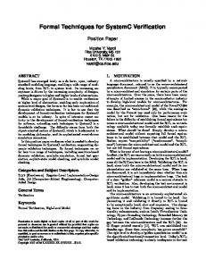
hardware and firmware.1 While synthesis of the HLM via behavioral compilers like Catapult C [Men] or Cynthesizer [For] should be aspired, current industry practice and investment into established hardware design flows still do not exploit this step and uses reimplementation in a hardware description language (HDL). Furthermore, to derive the full benefits of the proposed design flow it is assumed that the verification environment itself is developed manually from the informal specification while the HDL design proceeds. Moreover, due to human nature this process inevitable results in a verification environment containing bugs which are typically first noticed when a design under test (DUT) becomes available. In the following we will briefly discuss the EX Specification FWM two design flows depicted in Figure 1 a) for HLM Design FWH INT the traditional design flow and b) for the deFirmware Design HDL Design sign flow integrating HDL and firmware deHDL Verification VH Bringup velopment. First the traditional design flow in Figure 1a) is discussed. The exploration a) Example of a traditional industry hardware/software development design flow. phase EX selects the platform for the core EX functionality. After this phase the specificaSpecification FWVM SYN HLM Design INT tion is finalized and the implementation of Firmware Design firmware and hardware begins. In this flow Verification HDL Design firmware and hardware development are only VH Bringup tested against each other in phase FWH, by b) Design flow exploiting the HLM to integrate hardware using the HDL model, and in the final syssoftware verification efforts. tem integration phase INT. In phase FWM, the beginning of the firmware development, Figure 1: Comparison between design flows the HLM is used for testing purpose. Therewith and without proper integration fore, phase FWM has a higher firmware deof HLMs. velopment productivity than phase FWH as the HLM model is designed for efficient designer feedback to aid bug localization. The development of the HDL model and its verification environment proceed independently from the firmware development. The verification of the HDL model with the verification environment is performed in phase VH, which commences with the availability of the first HDL model prototype. With each new feature provided by the ongoing development of the HDL design new tests in the verification environment are executed for the first time. Moreover, during this phases both, the verification environment and the DUT, will contain bugs. Debugging in this phase is inefficient, since many verification and design engineers may need to get involved during bug localization and the HDL design is not the most appropriate model to provide feedback to aid bug localization. This problem is aggravated as the verification environment is solely used for verification of the HDL design. Due to the relative late availability of a first HDL design prototype, i.e., beginning of phase VH, the debugging of the verification environment itself is on the critical path directly impacting time to market of the product. In Figure 1b) a design flow integrating HDL model and firmware development by means of the HLM is presented. The exploration phase EX remains unchanged. However, in contrast to the tradition design flow the start of the implementation of the verification environment begins earlier and is used earlier in the FWVM phase. This phase combines firmware development and testing against the HLM with verification of the HLM model by the verification environment. Here, too, both the verification environment and the HLM will contain bugs but the HLM is much better suited to provide efficient feedback to aid bug localization. This ensures that as soon as the first HDL model is available and the switch over of the main verification effort from the HLM (Phase FWVM) to the HDL model (Phase VH) occurs, that the HDL verification only encounters very few verification environment bugs. This approach reduces the overall 1 Firmware
in this context is architectured Parallel Sysplex functionality, which is by a design decision implemented in software and not in hardware.
verification time compared to Figure 1a). In contrast to this the implementation efforts for the HLM increase as the HLM must be connected to the verification environment and is overall used longer in the design flow, i.e., phase SYN. Phase SYN ensures by usage of coverage measures that HDL and HLM functionality will not diverge for the scenarios covered by the verification environment. This enables a longer usage of the HLM for firmware development and its associated productivity advantage in contrast to the wholesale switch over of the firmware development to the HDL model as practiced in the design flow from Figure 1a). In this paper, we will show how a high-level modeling approach based on SystemC [GLMS02] can be used to satisfy the different requirements of both, hardware verification and firmware development. The applicability of the proposed approach to real-world designs will be illustrated by modeling and simulating a network controller for the Parallel Sysplex architecture used in IBM System z mainframes. The resulting model consists of more than 140,000 states and nearly 2,000,000 state transitions [ZFH+ 10]. However, the resulting description of the HLM consists of approximately 3k physical source lines of code (SLOC) [Whe09] written in SystemC, and has successfully been applied to HDL verification and firmware development. The corresponding HDL model consists of approximately 18k SLOC. The remainder of the paper is organized as follows: Related work will be discussed in Section 2. In Section 3, the basic modeling approach presented in [KSS+ 09] will be reviewed. In Section 5, the integrated verification approach will be discussed. Subsequently, we will study the application of the design flow to an industrial grade high-level model in Section 4.
2 Related Work Whereas the high simulation speed makes C/C++ models a first choice for virtual prototypes used in the software development [BdPV07], architectural exploration requires concurrency, which is supported by C/C++ only in an ad-hoc manner by various threading implementations. On the other hand, hardware description languages like VHDL and SystemVerilog are biased towards RTL implementations, and make high-level modeling painful by missing object-oriented features. The SystemC [GLMS02] C++ class library has become the de-facto industry standard to bridge the world of hardware and software design. Hence, C++ High-Level Models (HLM) can be effectively developed on top of the SystemC library. Furthermore, the importance of integrating verification efforts via usage of HLMs has already been recognized by industry [Swa06]. Moreover, while Bombieri et al. [BFP06] have shown that verification via high-level TLM test benches is as effective as RTL property checking derived from these test benches, they have neglected to consider the advantages of verification design flow which keep the HLM in sync with the derived HDL implementation over the whole design flow. To ensure that HDL and HLM functionality will not diverge, we use a functional coverage measure. However, SystemC allows an indefinite number of ways to write an HLM, which makes measuring of functional coverage a nontrivial problem. Integrating dataflow (DF) with finite state machines (FSM) has proven to be solution to combine concurrency with sequential processing on a high-level of abstraction. Furthermore, this allows to derive functional coverage measures directly from the model traces. One of the first modeling approaches integrating Finite State Machines (FSMs) with dataflow (DF) models is *charts (pronounced ”star charts”) [GLL99]. The *charts approach allows an arbitrary nesting of dataflow graphs and FSMs by either refining dataflow actors by FSMs or by refining states of an FSM by dataflow graphs. Other modeling approaches integrating FSMs with dataflow models are SysteMoC [KSS+ 09], the California Actor Language (CAL) [EJ03], and Extended Codesign Finite State Machines (ECFSMs) [SVSL00].
3 High-level Design Methodology To ensure that HDL and HLM functionality will not diverge we use a functional coverage measure. To enable a measurement of functional coverage, we use the integration of Finite State Machines (FSMs) with dataflow (DF) as the Model of Computation (MoC) for the HLM. This MoC has been implemented in the SysteMoC C++ library which is based on top of SystemC. The HLM of the Parallel Sysplex Network controller has been implemented in such a way, that the actions of the FSM have a good correspondence to high-level aspects from the specification, e.g., packet and interrupt types, connection modes, etc. Furthermore, high-level performance estimation, automatic hardware and software generation, and prototyping [KSS+ 09] are available for this design representation. In the following, we will briefly review the basics of the model to ease understanding of the later examples. In SysteMoC, an application is modeled by a network of actors, which are connected by channels with FIFO semantics. The basic entity of data transfer are tokens carrying data values of some data type, which are transmitted over these channels. Actors are only allowed to communicate with each other by means of these channels. More formally, an actor is defined as follows: Definition 3.1 (Actor) An actor is a tuple a = (I, O, F, R) containing actor ports partitioned into actor input ports I and actor output ports O, the actor functionality F partitioned into a set of datapath variables Vvar ⊂ F, action functions Faction ⊂ F and guard functions Gguard ⊂ F, and the actor FSM R controlling the communication behavior of the actor. The separation of computation represented by the actor functionality F from communication controlled by the actor FSM R allows subsequent analysis steps to abstract from the state of the actor functionality (i.e., a certain variable assignment) and only consider the state of the actor FSM, more formally defined below: Definition 3.2 (Actor FSM) The actor FSM is a tuple R = (Q, q0 , T ) containing a finite set of states Q and an initial state q0 ∈ Q. A transition t = (q, q0 , req, cons, gguard , faction ) ∈ T from a state q ∈ Q to a state q0 ∈ Q contains the enabling rate req : I ∪ O → N0 which maps each input/output port to the number of tokens/places required in order to execute the transition, and the consumption rate cons : I ∪ O → N0 (∀p ∈ I ∪ O : cons(p) ≤ req(p)) which maps each input/output port to the number of tokens/places consumed when the transition is executed. The guard function gguard ∈ Gguard is a boolean-valued expression over the values of the tokens required on the inputs and the datapath variables Vvar ⊂ F. Finally, the action function faction ∈ Faction determines the values of the tokens which are to be produced on the outputs and may modify the datapath variables contained in F. An FSM fragment is depicted in Figure 2. This fragment shows a hierarchical representation, as known from Statecharts [Har87], but from a semantic point of view, this can be transformed into its product automaton which is expressible by the actor FSM definition above. In the following, we illustrate the graphical notation by using the state diagram contained in hierarchical state sE from Figure 2 as an example. The number of tokens/places required for enabling a transition t and the number of consumed tokens/places by firing transition t is annotated via the p(t. req(p),t. cons(p)) notation.2 If the enabling rate is equal to the consumption rate of t, i.e., 2 We
use the ‘.’-operator, e.g., t. req, for member access of tuples whose members have been explicitly named in their definition, e.g., member req of the transition t as definedSin Definition 3.1. Moreover, this member access operator has a trivial extension to sets of tuples, e.g., A.I = a∈A a.I, which is also used throughout this document.
sA
sB sD
iAIB (1)& gisLIST & oAIB (1)/ ffetchPtr s1
4 iAIB (1)&
5
gisPtr sgotDataPtr
sgotGo
IN(sgotGo , SgotDataPtr )
3
s2 iLI (1)&gisGO
s0
sE
5
sF
5b
iAIB (1)&¬glastPayload & gisPtr
sC
7
s3
oAIB (1) &¬gptrEnd / ffetchData
oAIB (2)& gptrEnd / ffetchData ; 5c ffetchPtr s4 glastPayload sfetchIdle
s5 iAIB (1)& gisPayload & ¬glastPkt & oLI (1)/ fsendPkt
6 iAIB (1)& gisPayload & 8 glastPkt & oLI (1)/ fsendPkt ssendIdle
Figure 2: FSM fragment of a Parallel Sysplex endpoint. Concurrent FSM composition is denoted by the dashed lines. The fragment is responsible for sending payload data fetched directly from the memory subsystem via DMA accesses. The black highlighted numbers correlate to the operations in the sequence chart from Figure 3. t. req(p) = t. cons(p), only p(t. req(p)) is annotated, i.e., oAIB (2) is used to denote that at least two free places are required on port oAIB to activate the transition from state s3 to s4 . The guard function gguard is expressed as the remainder of the condition annotated to the transition, e.g., in this case gptrEnd . Finally, the action function faction is annotated after the slash, e.g., in this case calling ffetchData ; ffetchPtr in sequence. Firing this transition will also produce two tokens corresponding to the payload data fetch issued by ffetchData and an additional fetch of a new payload data segment address issued by ffetchPtr . This token production corresponds to the consumption of two free places, on port oAIB as req(oAIB ) = cons(oAIB ) = 2. The operational semantics of an actor FSM can be divided into three phases: (i) The current state is checked for an enabled transition t, i.e., sufficient tokens/places must be available on the input/output ports as specified by t. req, and the guard function t.gguard must evaluate to true. (ii) A single enabled transition is selected non-deterministically and executed, i.e., the action function t. faction is invoked which calculates the values of tokens to be produced based on the datapath variables and input tokens. (iii) Tokens/places are consumed from input/output ports as specified by t. cons. Actors are connected via their ports and a network graph to each other. The channels connecting the actors exhibit FIFO semantics.
4 Case Study In this section, we will briefly introduce parts of the Parallel Sysplex [NCB96, NMCB97] network controller and show how it has been modeled using the design methodology presented in Section 3. A Parallel Sysplex cluster consists of a number of servers which appear as a single system to users or applications. Each system contained in the cluster runs one or more instances of an operating system (OS), and is connected to a coupling facility (CF) that provides shared data structures (e.g., cache structures, list structures and lock structures), which can by used to synchronize the systems. Connections between coupling facility and operating system are facilitated by so called endpoints (EP).
from iLI
to oLI
from/to iAIB /oAIB
If an OS wants to read or modify a shared data structure in the CF, it has to send a primary message to the CF. After completion of the primary message, the CF may in turn send secondary messages to OS instances determined to have interest in the data structure that has been accessed or modified. The connection between the OS and the CF side is typically very latencysensitive. Therefore, a dedicated hardware engine, i.e., the Parallel Sysplex network controller, is used to minimize latency and CPU utilization. The Parallel Sysplex network controller is designed in such a way that all transport layer logic as well as the fetching and storing of the transmitted data is performed without any CPU involvement. For example, a sequence diagram of a primary message with write data from OS to CF is depicted in Figure 3. In Figure 2, the corresponding FSM fragment for the gray box on the OS side can be found. The packets generated by primary/seconOS side (S) CF side (R) dary messages are classified into four types: 1 WRITE MCB, MRB, and GO packets used for signaling FETCH MCB and flow control and DATA packets to transmit 2 MCB DATA the shared data structures. The Parallel SysMCB STORE MCB 3 LIST plex network controller has two primary inMCB STORED terfaces: The AIB Bus (iAIB /oAIB ) connected FETCH PTR to the memory subsystem and the CPU and INT./NOTIFY 4 PTR DATA the LI connection (iLI /oLI ) to the physical link LIST via the link interface. 5 GO FETCH PTR FETCH DATA In the following, we will briefly describe 6 DATA the interactions, as depicted in Figure 3, exePTR DATA DATA STORE DATA FETCH PTR cuted by a primary message with write data: DATA (1) The sequence is initiated by the applicaPTR DATA 7 tion via a WRITE command.3 This triggers a FETCH DATA DATA STORED memory fetch of the MCB data (2) which is DATA transmitted via the link interface (output oLI ) DATA FETCH PTR as an MCB packet by the network controller on 8 DATA the OS side as soon as the memory subsystem DATA STORED returns the data for the MCB fetch. (3) ConINT./NOTIFY PTR DATA currently, the application can submit a LIST TRIGGER command which specifies the address of the FETCH MRB scatter/gather list which is used to fetch the MRB DATA STORE DATA 9 MRB write data. This triggers a data pointer fetch, MRB STORED i.e., an entry of the scatter gather list, by the 10 network controller. (4) When the memory INT./NOTIFY subsystem returns the data pointer, the OS side is ready to transmit the data. (5) However, for the data transmission to begin, the Figure 3: Message sequence chart for a parallel sysplex primary message with CF side has to signal readiness by sending write data. the GO packet. This triggers data fetches by the network controller (5b), until the scatter gather list entry is running out of data (5c), resulting in a new data pointer fetch. (6) Concurrently, fetched data payload from the memory subsystem triggers data packet generation by the network controller. (7) When a new data pointer is returned by the memory subsystem, another data fetch cycle begins. (8) The data transmission is terminated when the last data packet has been send blocking the connection (9) 3 In
this context, a command is a single memory write operation to a memory region in which the I/O space of the parallel sysplex network controller has been mapped to. All these memory operations are performed over the AIB bus.
Test Bench
oASB
Parallel Sysplex oLI Network Controller iLI
iASB
a) Integration of the HLM into the HDL verification environment.
Valid seq.
iAIB
LI Driver
AIB Transactor ASB Transactor
oAIB HLM LI Transactor
AIB Driver ASB Driver
DUV with RTL equivalent interfaces
LIST FETCH PTR FETCH DATA GO LIST FETCH PTR GO FETCH DATA LIST GO FETCH PTR FETCH DATA GO LIST FETCH PTR FETCH DATA
... ... ... ...
Time
b) Valid sequences allowed by the specification and the subset (black) permissible by the implementation.
Figure 4: Integration of the HLM into the verification environment and difference between specification conforming sequences and possible sequences of an implementation. until an MRB packet has been received from the CF side. (10) With the final acknowledgment of the successful storage of the MRB data by the memory subsystem, the application will be notified of the completion of the primary message.
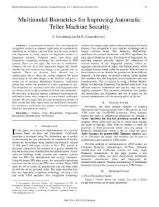
5 Verification Design Flow Executable High-Level Models (HLM) can be used to great advantage in many contexts, e.g., as has been shown for design space exploration in [KSS+ 09]. However, due to space limitation, we will focus on the usage of HLMs in the verification environment. The HLM, depicted in the dashed box in Figure 4a), is connected via so-called transactors to the bit-level interfaces used by the verification environment for RTL verification. This enables easy interchange of the device under verification (DUV) as either the HLM connected via the transactors or the RTL description. As can be seen from the figure, the HLM has three interfaces ASB, AIB, and LI: (i) The AIB interface provides the primary interface to the memory subsystem and the CPU. It is used for reception of parallel sysplex commands from the CPU, e.g., a LIST command in transition 3 from Figure 2, and fetching, e.g., transition 6 and 8, as well as storing of payload. (ii) The LI is the interface to the network link used for packet reception, e.g., GO packet in transition 5, and generation, e.g., payload packets in transition 6 and 8. (iii) Finally, the ASB interface, a similar but slower bus interface compared to the AIB bus, is only used for setup and administration tasks, therefore unused for packet processing. As the HLM is implemented as a SysteMoC model it is connected via six FIFO channels to the three transactors (two per transactor for both input and output direction). Theoretically, the testbench should only serve to check specification requirements in order to be reusable for all implementations of the specification. To exemplify, the specification imposes no constraint between the reception of the GO packet (transition 5) and the payload data fetching (transition 5b and 5c), i.e., it allows payload data to be buffered on the chip while waiting for the GO packet which signals the readiness of the peer endpoint to receive the data. The decision to fetch payload only after having received the GO packet, e.g., as encoded in the FSM by the decision to place transitions 5b and 5c in the hierarchical state sE while transition 5 is in sD , is an implementation decision, cf. Figure 4b). In the interest of a more thorough verification of the hardware, these implementation decisions are also checked. While this improves the verification of the hardware, it is problematic for follow-up projects which may take different implementation decisions. This will lead to testcase failures in the
verification environment, which have to be classified as either an implementation bug in the follow-up project or as a check for a implementation decision in the old project which has changed in the follow-up design. In this situation, the HLM can help to distinguish between specification requirement checks and implementation dependent checks, due to its independent implementation of the specification, i.e., it will exhibit different sequences than the HW. This indicates that either a more permissive test which can accept both sequences from HW and HLM has to be implemented or the test has to be marked as an implementation-specific test. This allows a clear separation of these two testing aspects in the testbench while new tests are initially developed, increasing the reusability of the verification environment for later projects. Furthermore, the verification design flow allows us to exploit the independent implementation efforts on the hardware RTL description, the verification environment, the high-level model, and the driver development to ensure that all specified functionality is indeed present and tested. These implementation efforts are required anyway as a direct usage of the RTL description of the parallel sysplex network controller for driver development has turned out to be infeasible due to the simulation performance penalties incurred by RTL simulations compared to high-level models. The verification design flow allows us to combine these efforts by means of the HLM which is used by the driver development team for early driver testing, therefore ensuring that all functionality required by the driver is present in the HLM. To ensure that this functionality is tested by the verification environment, we first record the transition trace ta ∈ a.R.T ∗ for each actor a ∈ A during the verification runs of the HLM. The action and guard functions executed by the transitions in the trace have a good correspondence to high-level specification requirement, e.g., packet and interrupt types to be supported, required connection modes, error scenarios to detect, etc. Therefore, we use the trace ta to estimate the functional coverage of an actor a by calculating the utilization C of the functionality, i.e.: C Fexecuted
|Fexecuted | where |Gguard ∪ Faction | = { f | ∃t ∈ ta : t.gguard = f ∨ t. faction = f } =
These coverage values derived from a trace are used as an indicator of the functional coverage achieved by the verification environment for the RTL implementation. The correctness of the testcase corresponding to the trace is checked by the verification environment. That the test has been performed is indicated by the coverage of the high-level specification requirement correlated to an action and guard function. Furthermore, due to the reuse of the verification environment for the RTL description we can assure that all required functionality by the developed driver is present in the hardware description of the chip. Moreover, there exists a feedback path via the structural coverage of the RTL description which ensures that the verification environment tests all implemented features of the hardware. These features are either also be tested for the HLM or a conscious decision has been made that this corresponds to functionality which cannot be represented in the HLM due to its more abstract implementation, e.g., for the parallel sysplex controller a conscious decision has been made to disable error testing of the bit-level AIB protocol. This protocol has been abstracted away in the HLM and is only present in the DUV to accommodate the HDL verification environment by providing the transactors to connect the HLM to the verification environment. A test for protocol errors on the AIB bus would only test these transactors, which are not included in the HLM for the firmware. Note that high-level errors like bad response codes from the memory subsystem are still tested. The overall impact of the HLM on the verification environment results in a better quality of the test suite.
6 Results The Parallel Sysplex network controller has been modeled using hierarchical FSMs one per endpoint (EP). In SystemC, the simulation phase is preceded by the so-called elaboration phase, during which the module hierarchy is created, and ports are bound to channels. During this phase, hierarchical FSMs (if any) are flattened in order to obtain the corresponding basic FSM corresponding to the design methodology presented in Section 3. In case of the hierarchical EP FSM, the corresponding basic FSM consists of 1,142 states and 14,537 transitions. Considering the 128 supported endpoints, the resulting model consists of more than 140,000 states and nearly 2,000,000 state transitions [ZFH+ 10]. Various features of the model contribute to the complexity of the model, e.g., more then a hundred concurrent connections, non-determinism in the specification, out-of-order processing of DMA reads and writes, error detection and reporting, endpoint recovery, and support for all variants of the WRITE, TRIGGER and LIST commands. With the presented verification design flow, a coverage of 95% was reached for the HighLevel Model (HLM). The remaining 5% pertain to corner cases which can not be triggered by timing the inputs, e.g., packets from the network and memory responses, to the HLM differently. Furthermore, covering these cases would not naturally improve the coverage of the HDL model as the internal logic of the HLM and the HDL implementation are different and these cases do not correspond to different input sequences. In the process, approximately 30 bugs in the verification environment itself and 60 bugs in the HLM have been found. Note that these bugs have been found before causing test case failure in the hardware verification or debugging in the software driver design flow. This is due to the early bring up of the verification environment and the HLM, where the functionality in the HLM constantly exceeded the functionality implemented by the hardware and the functionality required by the driver. This approach allows to validate new tests in the verification environment against new functionality in the HLM. Furthermore, the debugging of failed test cases is easier, due to both the higher abstraction level present in the verification environment and the HLM compared to the hardware implementation and the software driver. Finally, the performance of the HLM exceeds the performance of the IBM internal AWAN [KKS02] hardware accelerated VHDL simulator by a factor of three.
7 Conclusions Executable High-Level Models (HLM) are used to great advantage in many contexts, e.g., architectural exploration, hardware and software design flows, and integration & verification processes. However, in current industry practice each of these areas of the design flow uses a dedicated HLM neglecting the opportunity to cross-validate each others interpretation of the specification early in the design flow. We proposed a design flow for systems from the networking domain, which abstracts from the hardware platform by modeling the endpoint behavior by concurrent FSMs. The proposed flow is best suited for development from informal specifications where no preexisting verification environments are available. We showed the applicability of our proposed modeling approach by implementing and simulating a HLM for a complex Parallel Sysplex network controller. The HLM is used in both the software driver design flow and in the verification design flow. Therefore, the HLM links the specification requirements of the driver development team to the tested specification items in the hardware implementation. Furthermore, the shared development of the HLM between the driver development team and the verification engineers reducing the time-to-market by providing a tested verification environment earlier in the design process.
References [BdPV07]
L. Baldez, S. de Pena, and J. Vidal. The Unified Models Methodology: Applications to Inkjet Printing. In Proceedings of FDL, page 6, 2007.
[BFP06]
Nicola Bombieri, Franco Fummi, and Graziano Pravadelli. On the evaluation of transactor-based verification for reusing tlm assertions and testbenches at rtl. In DATE ’06: Proceedings of the conference on Design, automation and test in Europe, pages 1007–1012, 3001 Leuven, Belgium, Belgium, 2006. European Design and Automation Association.
[EJ03]
Johan Ecker and J¨orn W. Janneck. CAL Language Report – Language Version 1.0. Technical report, University of California at Berkeley, December 2003.
[For]
http://www.forteds.com.
[GLL99]
Alain Girault, Bilung Lee, and Edward A. Lee. Hierarchical Finite State Machines with Multiple Concurrency Models. IEEE Transactions on Computer-aided Design of Integrated Circuits and Systems, 18:742–760, 1999.
[GLMS02] Thorsten Gr¨otker, Stan Liao, Grant Martin, and Stuart Swan. System Design with SystemC. Kluwer Academic Publishers, 2002. [Har87]
D. Harel. Statecharts: A Visual Formalism for Complex Systems. Science of Computer Programming, 8(3):231–274, June 1987.
[HHP+ 07] K. Huang, S. I. Han, K. Popovici, L. Brisolara, X. Guerin, L. Li, X. Yan, S.-I. Chae, L. Carro, and A. A. Jerraya. Simulink-based MPSoC design flow: case study of Motion-JPEG and H.264. In Proceedings of DAC, pages 39–42, 2007. [ITR05]
ITRS. International Technology Roadmap for Semiconductors – Design. Technical report, ITRS, 2005. http://www.itrs.net/.
[KKS02]
J. Kayser, S. Koerner, and K.-D. Schubert. Hyper-Acceleration and HW/SW Co-Verification as an Essential Part of IBM eServer z900 Verification. In IBM Journal of Research and Developmen, volume 46, pages 597–605, July 2002.
[KSS+ 09]
Joachim Keinert, Martin Streub¨uhr, Thomas Schlichter, Joachim Falk, Jens Gladigau, Christian Haubelt, J¨urgen Teich, and Mike Meredith. SystemCoDesigner - An Automatic ESL Synthesis Approach by Design Space Exploration and Behavioral Synthesis for Streaming Applications. ACM Transactions on Design Automation of Electronic Systems (TODAES), 14(1):1–23, 2009.
[Men]
http://www.mentor.com.
[NCB96]
Jeffrey M. Nick, Jen-Yao Chung, and Nicholas S. Bowen. IBM System/390 Division: Overview of IBM System/390 Parallel Sysplex - A Commercial Parallel Processing System. In Proceedings of IPDPS, pages 488–495, Los Alamitos, CA, USA, 1996.
[NMCB97] J. M. Nick, B. B. Moore, J.-Y. Chung, and N. S. Bowen. S/390 cluster technology : Parallel Sysplex. IBM systems journal, 36:172–201, 1997. [SFH+ 06]
Martin Streub¨uhr, Joachim Falk, Christian Haubelt, J¨urgen Teich, Rainer Dorsch, and Thomas Schlipf. Task-Accurate Performance Modeling in SystemC for Real-Time Multi-Processor Architectures. In Proceedings of DATE, pages 480–481, Munich, Germany, March 2006. IEEE Computer Society.
[SVSL00]
Alberto Sangiovanni-Vincentelli, Marco Sgroi, and Luciano Lavagno. Communication-based Design. In Proceedings of CONCUR, August 2000.
[Swa06]
Stuart Swan. Systemc transaction level models and rtl verification. In DAC ’06: Proceedings of the 43rd annual Design Automation Conference, pages 90–92, New York, NY, USA, 2006. ACM.
[Whe09]
David Wheeler. Sloccount, 2009.
[ZFH+ 10]
Christian Zebelein, Joachim Falk, Christian Haubelt, J¨urgen Teich, and Rainer Dorsch. Efficient High-Level Modeling in the Networking Domain. In Proceedings of DATE (to appear), Dresden, Germany, March 2010. IEEE Computer Society.
Formal Models for