Predictive Runtime Verification of Multi-Processor SoCs in SystemC Alper Sen
Vinit Ogale
Magdy S. Abadir
Freescale Semiconductor Inc. Austin, Texas
Department of ECE University of Texas at Austin
Freescale Semiconductor Inc. Austin, Texas
[email protected]
[email protected]
ABSTRACT Concurrent interaction of multi-processor systems result in errors which are difficult to find. Traditional simulationbased verification techniques remove the concurrency information by arbitrary schedulings. We present a novel simulation-based technique for SystemC that preserves and exploits concurrency information. Our approach is unique in that we can detect potential errors in an observed execution, even if the error does not actually occur in that execution. We identify synchronization constructs in SystemC and develop predictive techniques for temporal assertion verification and deadlock detection. Our automated potential deadlock detection algorithm works on SystemC programs with semaphores, locks, wait and notify synchronizations and has less overhead compared with assertion verification. We patched SystemC kernel to implement our solution and obtained favorable results on industrial designs.
Categories and Subject Descriptors J.6 [COMPUTER-AIDED ENGINEERING]: Computeraided design (CAD)
General Terms Algorithms, Verification
Keywords Predictive Verification, Assertion, Deadlock, ESL, SystemC
1.
INTRODUCTION
Design and verification of systems that contain concurrently executing hardware and software components such as Multi-Processor System-on-Chips (MPSoC) is a challenging task. MPSoCs exploit concurrency to spread work around a system where as many software tasks can run at the same time as there are processors in the system. This tractability can be used to improve absolute performance, cost or power/performance. Concurrent systems have the property that multiple components can execute simultaneously, often interacting with each other. This results in extremely high
Permission to make digital or hard copies of all or part of this work for personal or classroom use is granted without fee provided that copies are not made or distributed for profit or commercial advantage and that copies bear this notice and the full citation on the first page. To copy otherwise, to republish, to post on servers or to redistribute to lists, requires prior specific permission and/or a fee. DAC 2008, June 8–13, 2008, Anaheim, California, USA. Copyright 2008 ACM ACM 978-1-60558-115-6/08/0006 ...$5.00.
[email protected]
numbers of possible execution paths and a very complex behavior of the system. Various scenarios of specific multiprocessor interaction can happen due to concurrency, which are often very difficult to find. We need verification techniques that can exploit concurrency in system level models. However, concurrency information is often lost in traditional simulation-based verification. That is because during execution of a design, the simulation scheduler (Verilog, VHDL, Java, or SystemC scheduler) puts an arbitrary ordering on executions of concurrent components. Hence, bugs that may reveal themselves on a different execution ordering of concurrent components can be missed. Raising the level of abstraction via system level design is one of the most efficient methods of reducing complexity due to concurrent electronic designs. It is easier to diagnose concurrency and protocol problems at the system level, whereas these problems are hidden at the lower implementation levels. Increasing design costs are also pushing design, analysis and verification to abstract levels rather than the traditional implementation levels such as Verilog or VHDL. SystemC is the most popular system level modeling language used for designing SoCs in the industry. It is a C++ library that contains constructs related to concurrency, time and hardware data types. It is freely available from OSCI [12] and is an IEEE standard. However, system level design coupled with multi-processors is a challenge to EDA tool providers, and system level tools are still in their infancy. New system level techniques of analysis are required to improve reliability of concurrent software running on concurrent hardware. In this paper, we develop novel Predictive Runtime Verification (PRV) techniques that preserve concurrency information (schedules) and exploit it to find both actual and potential errors from executions of SystemC models. PRV is similar to simulation-based approaches such as Assertion Based Verification (ABV) in that assertions can be used for specifying correctness conditions. However, it is different from traditional simulation-based approaches, in that it can detect potential errors in an observed execution, even if the error does not actually occur in that execution. This is a valuable debugging tool that can greatly increase the detection of hard-to-find scheduling dependent errors during simulation. Potential error detection is possible in our approach due to preserving and exploiting concurrency information by tracking dependencies during the execution of a system. Using this information, we obtain a partial order execution trace as opposed to a total order trace, which traditional simulation-based approaches generate. In partial order traces, only causally dependent actions are ordered,
1 2 4 5 6 7 8 9 10 11 12 13 14 15 16
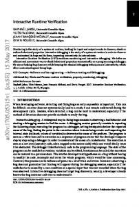
SCMODULE(M1) { bool c s 1 , c s 2 ; SC CTOR(M1) { SCTHREAD( T1 ) ; SCTHREAD( T2 ) ; c s 1 = true ; cs2 = false ; } void T1 ( ) { cs1 = false ; } void T2 ( ) { c s 2 = true ; } };
Assertion : c s 1 = true and c s 2 = true Trace 1 : ( No v i o l a t i o n ) −−−−−−−−−−−− T1 : c s 1 = f a l s e ; T2 : c s 2 = true ; Trace 2 : ( violation ) −−−−−−−−−−−− T2 : c s 2 = true ; T1 : c s 1 = f a l s e ;
Figure 1: A SystemC design and its execution traces
hence concurrent actions are not artificially ordered. Concurrency related errors can also be introduced due to common synchronization mechanisms such as locks, semaphores, and condition variables. These errors result in deadlocks, which can also be masked by the simulator due to nondeterministic scheduling. Using dependency tracking mechanisms, we developed automatic deadlock detection techniques that have the ability to find potential violations of these synchronization mechanisms. In this case, the user does not need to specify the assertion, since it seems redundant to write an application specific deadlock detecting assertion for every design. One of our major requirements for implementation is to obtain a scalable and fast solution that can be seamlessly integrated with current design flows. Techniques based on translating SystemC models to an internal formal model are not scalable to real complex designs. Furthermore, we did not want to modify the designer’s code. Hence, we chose to modify SystemC simulation kernel and implemented our algorithms for predictive verification. Similar to other simulationbased verification methods, our technique works on executions and, not on programs, hence we do not analyze the effect of different inputs to the systems. We performed experiments with industrial designs to validate effectiveness of our verification environment. We found errors on earlier tested systems. To the best of our knowledge, there is no known previous work on finding potential synchronization errors in SystemC. We summarize the contributions of this paper as follows: • Predictive Runtime Verification for SystemC. • SystemC kernel modifications to track dependency information. • Automated predictive assertion verification framework. • Automated predictive deadlock detection framework. • Experimental results on industrial designs. A Motivating SystemC Example: We now present a simple example to demonstrate concurrency related problems that are missed by traditional simulations. Figure 1 displays a SystemC module M1 with two threads T1 and T2 that control variables cs1 and cs2, respectively. In this example, threads are independent of each other, that is, not communicating. Initially, cs1 is true and cs2 is false. We are interested in checking an error condition, whether both cs1 and cs2 can be true at the same time. While simulating this SystemC design, the simulation scheduler can non-deterministically choose to execute T1 or T2 first. This is because both statements in lines 11 and
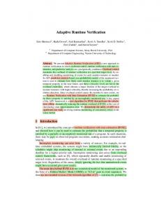
Figure 2: Partial order trace with vector clocks
14 are concurrent. If the scheduler chooses to execute T1 first, we obtain Trace 1, otherwise Trace 2. Note that the specification is not violated in Trace 1 but in Trace 2. If we had only observed Trace 1, we would have missed the error in the design. Our technique can generate equivalent execution Trace 2 from Trace 1 without re-executing the design and find the potential error. So, how do we preserve concurrency information and obtain equivalent executions without re-executing the design? For this, we employ a technique commonly used in distributed computing called vector clocks, which we explain next.
2.
VECTOR CLOCKS
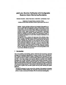
Instead of using an actual time stamp in the simulation, we use a vector of logical time stamps to track the concurrency information or the dependencies amongst the actions in a trace. A partial order relation known as Lamport’s happened-before relation [9] has been used for modeling concurrency information in distributed computing. We assume that execution of a process (thread or method) can generate either an internal action, send action or a receive action. Lamport’s happened-before relation is defined as the smallest transitive relation satisfying the following properties: (a) if actions e and f are generated by the same process, and e occurred before f in real time then e happened-before f , and (b) if actions e and f correspond to the send and receive, respectively, of a message then e happened-before f . We use vector clocks [4, 10] to represent the partial order relation (the happened-before relation). A vector clock assigns timestamps to actions such that the partial order relation between actions can be determined by using the timestamps. For example, given an n process program, for every process j, we assign a vector clock of size n, denoted by vj . Initially, vj [i] = 0, for i 6= j, and vj [j] = 1. A process increments its own component of the vector clock after each action. It also includes a copy of its vector clock in every outgoing message. On receiving a message, it updates its vector clock by taking a component wise maximum with the vector clock included in the message. A sample execution of the vector clock algorithm is given in Figure 2, where the tuples in brackets represent the vector clocks. In the example, action s happened-before t since [1, 0, 0] < [2, 1, 3], where vi < vj if all elements of vi are less than or equal to the corresponding elements of vj and at least one element of vi is strictly less than the corresponding element of vj . Whereas u is concurrent with t since their vector clocks are not comparable.
3.
SYSTEMC SIMULATION SCHEDULER
SystemC has the concept of processes (described in the
sc process class) to model the concurrent activities of a system. Processes can be combined into modules to create hierarchies. Process registration and module interconnection happen during the elaboration phase (during the execution of the constructor for the SC M ODU LE class). Processes access external channel interface through the ports of a module. Processes run concurrently, but code inside a process is sequential. There are two types of processes, method process (sc method process), thread process (sc thread process). The SystemC scheduler controls the timing and order of process execution, handles event notifications and manages updates to channels. It is an event-based simulator similar to VHDL. SystemC processes are non-preemptive. Hence, a process has to voluntarily yield control for another process to be executed. Threads are run exactly once by the kernel and typically have a loop that keeps the thread alive for the duration required. The program-flow control remains with the thread till it explicitly yields. The thread then stays in a wait state until some event triggers it, and it resumes execution from the next statement after wait. A method executes atomically and cannot yield to another process. The simulator regains control after the entire method has been executed. The SystemC scheduler supports delta-cycles. A deltacycle consists of the execution of evaluate and update phases. This is generally used to model primitive channels that cannot change instantaneously, such as sc signal, similar to registers in HDL. Once started the scheduler continues until either there are no more events, a process explicitly stops it, or an exception condition occurs (implemented in the sc simcontext class). The following displays the steps of the simulation scheduler in more detail. 1. Initialization: Execute all processes in an unspecified order. 2. Evaluate: Select a ready-to-run process and resume its execution. This may result in more processes ready for execution in this same phase due to immediate notification. 3. Repeat 2 until no more processes are ready-to-run. 4. Update: Execute all pending update requests due to calls made in Step 2. 5. If Steps 2 or 4 resulted in delta event notifications, go back to Step 2. 6. If there are no more events, simulation is finished for current time. 7. Advance to next simulation time that has pending events. If none, exit simulation. 8. Go back to Step 2.
4.
SYNCHRONIZATION IN SYSTEMC
Processes are triggered and synchronized with respect to sensitivity on events. An event keeps the list of processes that are sensitive to it and informs the scheduler which processes to trigger. Concretely, an event is used to represent a condition that may occur during the simulation. A SystemC event is the occurrence of an sc event notification and happens at a single point in time. An event has no duration or value. There are two types of sensitivity. Static sensitivity is defined before simulation starts such as sensitivity to a clock signal, and dynamic sensitivity is defined after simulation starts and can be altered during simulation. Events are controlled via wait, next trigger and notif y functions of the sc event class.
A wait function changes dynamic sensitivity of a thread process and suspends its execution. For example, wait(0) delays the process by one delta cycle, whereas process waits on event e with wait(e). Similarly, a next trigger function changes dynamic sensitivity of a method process. However, this function returns immediately rather than suspending execution. Events occur explicitly by using the notif y function and the scheduler resumes execution of a thread or method process by executing the trigger function. For example, e.notif y() is called an immediate notification since processes sensitive to event e will run in the current evaluation phase or delta cycle. Similar to events; channels, interfaces, and ports are used for process synchronization and also for communication refinement. These constructs are the core of Transaction Level Model (TLM) based methodology and are defined as follows. A channel implements interfaces. Channels hold and transmit data. An interface is a declaration of the available functions for accessing a given channel and describes the set or subset of operations that the channel provides. A port is bound to a channel through an interface and it is an agent that forwards function calls up to the channel on behalf of the calling module. Channel functions read and write generate synchronization between processes. In fact, channels instantiate sc event objects to synchronise concurrent processes. Synchronization is also established through instantiating sc semaphore and sc mutex objects, which provide wait, trywait, post and lock, trylock, unlock functions, respectively. These functions also call low level wait and notif y functions from sc event class. In summary, synchronization happens through functions notif y, wait, next trigger, trigger on events, read, write on channels, wait, trywait, post on semaphores, and lock, trylock, unlock on locks. Also, note that communication between processes is established by explicit synchronization constructs rather than shared variables in TLM methodology. However, it is possible to handle shared variables using dynamic vector clocks [14].
5.
SYSTEMC KERNEL MODIFICATIONS
We added a new class sctv vector clock to implement vector clocks. Every send and receive is considered to be an action. By default, every delta-cycle is registered as an internal action. Note that a single delta-cycle can consist of multiple concurrent actions. During the elaboration phase of the simulation, the processes are registered, the total number of processes in the system is determined, and the appropriately sized vector clocks are instantiated. Every process in the design has the extra data member consisting of the vector clock. class sct v v ect o r cl o ck { ... void r e c e i v e m e s s a g e a c t i o n ( const s c t v v e c t o r c l o c k& vc ) { f o r ( i n t i= 0 ; i < v c s i z e ; i +=1){ i f ( c l o c k [ i ] < vc . c l o c k [ i ] ) { c l o c k [ i ] = vc . c l o c k [ i ] ; } } c l o c k [ my id ] +=1; w r i t e t o t r a c e ( ) ; } void s e n d m e s s a g e a c t i o n ( ) { c l o c k [ my id ] +=1; write to trace (); }
void i n t e r n a l a c t i o n ( ) { c l o c k [ my id ] +=1; w r i t e t o t r a c e ( ) ; } void copyFrom ( const s c t v v e c t o r c l o c k& vc ) { f o r ( i n t i =0 ; i < v c s i z e ; i +=1){ clock [ i ] = vector clock . clock [ i ] ; } } };
As we discussed above, the communication framework in SystemC is based around events. SystemC events are stateless and extremely lightweight. A trigger event (resulting after a wait) or a channel read corresponds to a receive action in the partial order trace. Similarly, a notify event or a channel write (which later invokes notify) corresponds to a send action in the trace. It is convenient to have the sender information when a message is received. Hence, we add the sender id to every event. For a trigger event, the sender id is checked. If the sender id is invalid, we conclude that the event is an internal action. e.g. a timed wait event. Since an event corresponds to an action in our partial order trace model, as per the vector clock algorithm, the vector clock of the sending process is stored with the event. Note that, for channel writes, the events are initialized after the current process has finished executing. Hence we store the required information in the sc prim channel class. This works for the primitive channels as well as any user defined channels. void sc event : : n o t i f y ( ) { ... // h a n d l e = s e n d e r p r o c e s s s e n d e r = h a ndl e−>p r o c i d ; // s e t t h i s e v e n t s v e c t o r c l o c k v e c t o r c l o c k . copyFrom ( ha ndl e−>v e c t o r c l o c k ) ; // increment s e n d e r s v e c t o r c l o c k h a n d l e−>v e c t o r c l o c k . s e n d m e s s a g e a c t i o n ( ) ; // t r i g g e r p r o c e s s e s s e n s i t i v e t o t h i s e v e n t trigger (); }
The dependencies are dynamically generated as the program is executed. We next show a code snippet that displays modifications in the trigger function in the sc event class that corresponds to a receive action. We treat AN D and OR event lists separately. In particular, we receive the vector clock for each notifying process in AN D case, whereas the first notifying process’s vector clock suffices in the OR case. void sc event : : t r i g g e r ( ) { ... // t r i g g e r t h e dynamic s e n s i t i v e t h r e a d s i f ( ( s i z e = m t h r e a d s d y n a m i c . s i z e ( ) ) != 0 ) { int i = s i z e − 1 ; // f o r each s e n s i t i v e t h r e a d do { // c h e c k w h e th e r t h e t h r e a d i s e l i g i b l e t o run // c o n s i d e r i n g s e n s i t i v i t y t o AND, OR e v e n t l i s t s // make each e l i g i b l e t h r e a d r u n n a b l e ... i f ( s e n d e r >=0) { // r e c e i v e a c t i o n i n t r e c e i v e r I d = t h r e a d h −>p r o c i d ; // r e c e i v e v e c t o r c l o c k o f p r o c e s s t h r e a d h −>v e c t o r c l o c k . r e c e i v e m e s s a g e a c t i o n ( t h r e a d h −>r e c e i v e d v e c t o r c l o c k s [ i ] ) ; } e l s e { // i n t e r n a l a c t i o n i n t r e c e i v e r I d = t h r e a d h −>p r o c i d ; t h r e a d h −>v e c t o r c l o c k . i n t e r n a l a c t i o n ( ) ; } } while ( −− i >= 0 ) ; } ... }
We also modified the kernel in order to trace relevant variables for the assertion in question. The tracing syntax for
variables in partial order traces is very similar to the sc trace syntax. After the user specifies an assertion, relevant variables are automatically extracted and traced. This is done such that designer’s code is unmodified. Anytime a synchronization event or a relevant variable change occurs, variable values along with the corresponding vector clocks are written to the trace file.
6.
PREDICTIVE ASSERTION VERIFICATION
Given a SystemC design and an assertion, our automated assertion verification flow consists of the following steps: 1. The assertion is read, and the relevant variables of interest are determined. 2. Automatically add tracing for relevant variables. 3. The design is compiled and executed with the modified kernel, generating a trace. 4. The resulting partial order trace and the assertion are passed to the verifier tool, which determines whether the assertion is satisfied or not. Figure 3 demonstrates an example where we are interested in checking whether eventually cs1 and cs2 are true at the same time. (Steps 1 and 2) The relevant variables of this assertion are cs1 from thread 1 and cs2 from thread 2. Our framework automatically adds tracing for these relevant variables to the design as explained above. (Step 3) When this design is compiled and executed with our modified kernel, a trace that contains internal, send and receive actions from every thread together with the values of relevant variables and vector clocks for every action is generated. Trace 1 corresponds to this generated trace. Note that for efficiency reasons we do not generate actions in the traces for the wait function. We can obtain The partial order trace shown in the figure from Trace 1 using the vector clock information in Trace 1. (Step 4) Then we can check the satisfaction of this conjunctive assertion on the partial order trace as follows. Starting from the initial state of the partial order trace, that is, (T1:[1,0], T2:[0,1]), we move right (toward the end of the trace) one action at a time while generating a consistent global state and checking whether the assertion cs1 ∧ cs2 is satisfied or not on that global state. A consistent global state of a partial order trace is given by the set of actions that have been executed last on all threads such that causality is respected. For example, (T1:[1,0], T2:[2,2]) is not a consistent global state since it depicts a situation where a message has been received by T2 but it has not been sent by T1 yet. Since initially the assertion is not satisfied, that is, cs1 is true and cs2 is false, we move right on T2 in order to make cs2 true, but we cannot because the resulting global state (T1:[1,0], T2:[2,2]) would be inconsistent. Therefore, we move right on T1, generating consistent global state (T1: [2,0], T2:[0,1]). We continue this procedure until the assertion is satisfied or we reach the end of the trace. In this example, the assertion is satisfied at consistent global state (T1:[2,0], T2:[2,3]) since cs1 ∧ cs2 is true. However, note that the assertion is not satisfied in the total order Trace 1, which was what the user observed. Indeed, this error could have been found only if the user had observed another total order Trace 2. Hence, our framework is able to find potential errors from successful total order traces (Trace 1). Note that, once the partial order trace is obtained, the design is never re-executed in order to find other possible traces (Trace 2), rather our algorithms work
1 2 3 5 6 7 8 9 10 11 12 13 14 15 16 17 18 19 20 21 22 23 24 25 26 27
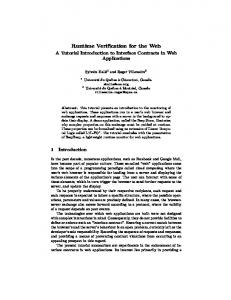
SCMODULE M1 { sc event e ; bool c s 1 , c s 2 ; SC CTOR(M1) { SCTHREAD( T1 ) ; SCTHREAD( T2 ) ; // i n t e r n a l a c t i o n c s 1 = true ; // i n t e r n a l a c t i o n cs2 = false ; } void T1 ( ) { // send a c t i o n e . notify ( ) ; // i n t e r n a l a c t i o n wait ( 0 ) ; // i n t e r n a l a c t i o n cs1 = false ; } void T2 ( ) { // r e c e i v e a c t i o n wait ( e ) ; // i n t e r n a l a c t i o n c s 2 = true ; } };
Partial
Order
Trace:
Assertion : −−−−−−−−−− Eventually c s 1=true and c s 2=true Beginning of t r a c e s : [ 1 , 0 ] T1 : c s 1 = true ; [ 0 , 1 ] T2 : c s 2 = f a l s e ; T o t a l Order Trace 1 : −−−−−−−−−−−−−−−−−−−− T2 : wait ( e ) ; [ 2 , 0 ] T1 : e . n o t i f y ( ) ; T1 : wait ( 0 ) ; [ 3 , 0 ] T1 : t r i g g e r [ 4 , 0 ] T1 : c s 1 = f a l s e ; [ 2 , 2 ] T2 : t r i g g e r [ 2 , 3 ] T2 : c s 2 = true ; T o t a l Order Trace 2 : −−−−−−−−−−−−−−−−−−−− T2 : wait ( e ) ; [ 2 , 0 ] T1 : e . n o t i f y ( ) ; T1 : wait ( 0 ) ; [ 2 , 2 ] T2 : t r i g g e r [ 2 , 3 ] T2 : c s 2 = true ; [ 3 , 0 ] T1 : t r i g g e r [ 4 , 0 ] T1 : c s 1 = f a l s e ; T o t a l Order Trace 3 : −−−−−−−−−−−−−−−−−−−− [ 2 , 0 ] T1 : e . n o t i f y ( ) ; T1 : wait ( 0 ) ; [ 3 , 0 ] T1 : t r i g g e r [ 4 , 0 ] T1 : c s 1 = f a l s e ; T2 : wait ( e ) ;
Figure 3: A SystemC design, its total order and partial order execution traces on the partial order trace itself. Efficient temporal assertion verification algorithms for partial order traces used in the verifier tool can be found in our earlier work [13].
7.
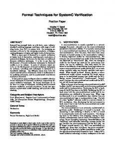
essarily missed in the actual observed Trace 1. If there exists a potential missed notification, then we could always have an execution where the receiving process never makes any further progress. Hence the processes that depend on the original receiver also stop making progress. We start generating a dependency graph for every missed notification and if there exists a loop, then the algorithm signals a potential deadlock. Note that, in the case of timed event waits,we generate a separate process to send the notification. Also, for ORed waits, we use the static information to determine the list of notifiers. Figure 4 displays a trace with three threads, where the notification from the first thread T1 is potentially missed by T2, hence the dotted arrow in the figure. Then, both T2 and T3 stop making progress, and since T1 depends on T3, we obtain a cycle, hence a potential deadlock although the observed execution was deadlock free.
PREDICTIVE DEADLOCK DETECTION
The verification methodology described so far relies on user defined assertions. This is a powerful way to detect bugs and can easily accommodate most types of assertions. However, deadlocks are almost always undesirable in any system. Hence, it seems inefficient to write an application specific deadlock detecting assertion for every design. We say that a deadlock occurs in a system if two or more components are each waiting for the other to complete before proceeding. Automatic deadlock detection is very useful in a verification flow. However, due to the inherent concurrency in the system, a deadlock that may not occur in one execution (and hence is undetectable by existing techniques) may occur in another execution. This effect is especially pronounced when the processes operate independently of each other, for example, in a multi-processor system, where each processor is frequency throttled independently of the other. We call such deadlocks potential deadlocks. We say that a notification is missed if the corresponding process is not in waiting state at the time of notification. Trace 3 in Figure 3 demonstrates a case where T2 freezes due to missing the notification sent by T1. Potential deadlocks can occur when it is possible to miss a sent notification by freezing the receiving process. We call this a potential missed notification. In this case, the notification is not nec-
Figure 4: Automatic Potential Deadlock Detection We can find actual deadlocks using a simpler algorithm as in [2] by building a dependency graph of wait/notify dependencies, where edges are added when waiting and are removed when notified. We then check for cycles in the dependency graph.
8.
EXPERIMENTAL RESULTS
We performed experiments with two industrial SystemC frameworks where we could turn on or off our modifications. The first framework is a modeling library based on SystemC used for architectural exploration, RTL development, constrained random verification, and early software development. It includes a complete set of BFM and monitor components for several bus protocols including proprietary TLM compliant bus protocols. Also, included is a new testbench environment built on the existing hardware modeling library, that includes controllers through which all interaction with the device under verification takes place. Some of the controllers are data stimulus, clock, signal, bus, fifo, and memory. The framework consists of around 40,000 lines of SystemC code. The experiments were executed with up to 12 threads. We used 21 testbenches that were used during original validation and found potential deadlocks in 4 cases. These errors were due to the synchronization between SystemC TLM library and SystemC models. The average slowdown on simulation using our kernel with potential deadlock detection versus the unmodified kernel was 7%. The second framework is an SOC with DSP cores, cryptographic accelerators, and crossbar. The code base was 100,000 lines of SystemC code. There were 57 threads maximum during the experiments. We used 6 testbenches that were used during original validation of the design. We detected 13 missed notifications but did not find any potential deadlocks. We also manually inserted errors and checked several temporal assertions. We caught these errors by our
predictive verification framework, whereas errors were not found by a traditional assertion based verifier since the observed simulation did not have the error. Our initial experiments demonstrate a 12% slowdown on simulation versus the unmodified kernel. Designs with higher number of processes have a higher slowdown as expected. Our experiments demonstrate that predictive runtime verification is a useful technique to prune out potential errors. Predictive deadlock detection is an on-line algorithm that does not use the entire partial order trace. Therefore, it has less impact than predictive assertion verification, which works off-line and needs all of the partial order trace to detect complex temporal assertions.
9.
RELATED WORK
We describe related work in SystemC verification, instrumentation and assertion based verification as it relates to this paper. Formal verification of SystemC designs has been studied in [5]. Due to the state space search, formal techniques are limited in practice. Furthermore, these techniques can only translate a subset of SystemC into an FSM model. Vardi [15] presents a summary of formal techniques in SystemC context. Helmstetter et al. [7] generate different SystemC schedulings to improve test coverage using dynamic partial order reductions. This is different from our work since our goal is assertion based verification. Partial order reduction is orthogonal to our approach and can be used in conjunction. Also, they use PINAPA parser [11] which uses a limited SystemC subset, whereas we do not depend on any external parser. Agarwal et al. [1] deal with potential deadlock detection in a general setting, whereas we focus on SystemC. They exhaustively generate equivalent executions and perform a costly state space search, whereas we do not use a state-space based approach. Also, our potential deadlock detection algorithm uses a circular dependency tracking, which they do not have. Cheung et al. [2] present an automated deadlock detection algorithm for SystemC based on static information. Their work cannot predict potential deadlocks, rather they can find actual deadlocks faster than normal simulations. System Verilog Assertions have been used for SystemC descriptions [6]. SystemC specific transaction level assertions have also been developed [8, 3]. There is a growing vendor tool support for SystemC modeling and verification. Our work is similar to other assertion based verification tools that do not abstract the design, but it is different in that we can find potential errors. Partial order execution traces for multi-threaded Java programs have been analyzed in [14, 13], whereas we analyze partial order traces for SystemC and we have automatic potential deadlock analysis.
10.
CONCLUSIONS AND FUTURE WORK
The inevitable switch to multi-processor designs is causing a fundamental shift in system design automation. There is great demand for working tools to preserve concurrency and find potential concurrency related errors. We developed and implemented predictive techniques for temporal assertion verification and deadlock detection of SystemC designs. Our experimental results on industrial designs validate the effectiveness of predictive runtime verification. We plan to develop on-line versions of our verification algorithms and investigate efficient vector clock algorithms. We are also planning to extend our framework to transaction level as-
sertions.
11.
REFERENCES
[1] R. Agarwal and S. D. Stoller. Run-Time Detection of Potential Deadlocks for Programs with Locks, Semaphores, and Condition Variables. In Proceedings of the Workshop on Parallel and Distributed Systems: Testing and Debugging (PADTAD), 2006. [2] E. Cheung, P. Satapathy, V. Pham, H. Hsieh, and X. Chen. Runtime Deadlock Analysis of SystemC Designs. In Proceedings of the IEEE International High-Level Design Validation and Test Workshop (HLDVT), 2006. [3] W. Ecker, V. Esen, T. Steininger, M. Velten, and M. Hull. Implementation of a Transaction Level Assertion Framework in SystemC. In Proceedings of the Conference on Design Automation and Test in Europe (DATE), 2007. [4] C. Fidge. Logical Time in Distributed Computing Systems. IEEE Computer, 24(8):28–33, Aug. 1991. [5] D. Grosse and R. Drechsler. Formal verification of LTL formulas for SystemC designs. In Proceedings of the International Symposium on Circuits and Systems (ISCAS), 2003. [6] A. Habibi and S. Tahar. On the extension of SystemC by SystemVerilog assertions. In Proceedings of Canadian Conference on Electrical and Computer Engineering, 2004. [7] C. Helmstetter, F. Maraninchi, L. Maillet-Contoz, and M. Moy. Automatic Generation of Schedulings for Improving the Test Coverage of Systems-on-a-Chip. In Proceedings of the International Conference on Formal Methods in Computer Aided Design (FMCAD), 2006. [8] A. Kasuya and T. Tesfaye. Verification methodologies in a TLM-to-RTL design flow. In Proceedings of the Design Automation Conference (DAC), 2007. [9] L. Lamport. Time, Clocks, and the Ordering of Events in a Distributed System. Communications of the ACM (CACM), 21(7):558–565, July 1978. [10] F. Mattern. Virtual Time and Global States of Distributed Systems. In Parallel and Distributed Algorithms: Proceedings of the Workshop on Distributed Algorithms (WDAG), 1989. [11] M. Moy, F. Maraninchi, and L. Maillet-Contoz. LusSy: A Toolbox for the Analysis of Systems-on-a-Chip at the Transactional Level. In Int’l Conference on Application of Concurrency to System Design, 2005. [12] Open SystemC Initiative, http://www.systemc.org/. [13] A. Sen and V. K. Garg. Formal Verification of Simulation Traces Using Computation Slicing. IEEE Transactions on Computers, 56(4):511–527, Apr. 2007. [14] K. Sen, G. Rosu, and G. Agha. Runtime Safety Analysis of Multithreaded Programs. In Proceedings of the Symposium on the Foundations of Software Engineering (FSE), 2003. [15] M. Y. Vardi. Formal Techniques for SystemC Verification; Position Paper. In Proceedings of the Design Automation Conference (DAC), 2007.