Testbed. Our experimental testbed is comprised of three robotsâ a crane, a roving eye and a mobile manipulator (Figure 2). The crane, called Robocrane, is a ...
First Results in the Coordination of Heterogeneous Robots for Large-Scale Assembly Reid Simmons, Sanjiv Singh, David Hershberger, Josue Ramos, Trey Smith Robotics Institute Carnegie Mellon University Pittsburgh, PA 15217 {reids, ssingh, hersh, josue, trey}@ri.cmu.edu Abstract: While many multi-robot systems rely on fortuitous cooperation between agents, some tasks, such as the assembly of large structures, require tighter coordination. We present a general software architecture for coordinating heterogeneous robots that allows for both autonomy of the individual agents as well as explicit coordination. This paper presents recent results with three robots with very different configurations. Working as a team, these robots are able to perform a high-precision docking task that none could achieve individually.
1. Introduction As robots become more autonomous and sophisticated, they are increasingly being used for more complex and demanding tasks. Often, single robots are insufficient to perform the tasks. For some types of tasks, such as exploration or demining, multiple robots can be used to increase efficiency and reliability. For many other tasks, however, not only are multiple robots necessary, but explicit coordination amongst the robots is imperative. Our research focus is on the latter class of problems, particularly those in which the individual robots have vastly different capabilities. For many tasks, the use of heterogeneous robots is indicated because of the difficulties of constructing a single robot that has the needed size, strength, dexterity, etc. One such application domain is assembly of large-scale structures, such as terrestrial buildings, planetary habitats, or space solar power structures. Such domains need both heavy lifting capabilities, as well as precise, dexterous manipulation to connect parts together. A motivating scenario is that of assembling the steel structure of a large building. In such cases, a large crane is used to lift beams and move them near their destinations; a worker near the destination uses hand signals to guide the crane operator; when the beam is close enough, the worker grabs the end and moves it into place. Our short-term research goal is to accomplish that scenario using a team of three autonomous robots. Our initial assembly scenario is to emplace a long heavy beam precisely. This task needs both strength and dexterity. Our approach is to coordinate three robots— an overhead crane, a mobile manipulator, and a roving eye. The crane provides heavy lifting capability and has a large workspace, but is not precise; the manipulator provides dexterity and precise control, but is weaker and has a relatively smaller workspace from a fixed position of the base; the roving eye provides accurate
views of the workspace, which are used to guide the other two robots. This task has been chosen to highlight issues with heterogeneous robots. Research issues include techniques for explicit coordination between the robots, distributed visual servoing, planning and execution techniques that take advantage of the heterogeneous nature of the robot team, and robust monitoring and exception handling within teams. Longer-term issues include dynamic team formation with large numbers of robots and high-level, distributed planning for building complex structures with many parts. In this paper we present our approach and compare it with work done by other researchers. We discuss two topics, distributed coordination and distributed visual servoing, in the context of a beam placement task accomplished by a team of three robots.
2. Approach Our approach to coordinating multiple, heterogeneous robots is based on the layered architectures that are becoming increasingly popular for single-agent autonomous systems [3], [12], [17]. In our architecture, each robot is an autonomous agent, consisting of a planning layer that decides how to achieve high-level goals, an executive layer that synchronizes agents, sequences tasks and monitors task execution, and a behavioral layer that interfaces to the robot’s sensors and effectors (Figure 1). As is customary with single-agent tiered architectures, each layer interacts with those above and below it. In addition, in our multi-robot architecture, agents can interact with one another through direct connections at each of the three layers. This type of layer-specific interaction provides for increased flexibility and efficiency in the way the robots can coordinate. Planner
Planner
Planner
Executive
Executive
Executive
Behaviors
Behaviors
Behaviors
Robot1
Robot 2
Robot 3
Figure 1. Layered multi-robot architecture. Each robot has three layers that can directly interact with one another and with the appropriate layers of the other robots.
For instance, the behavioral level typically consists of sensor/effector feedback loops. By allowing connections between the sensor behaviors of one robot and the effector behaviors of another, we create efficient distributed servo loops, such as the visual servoing described in Section 6. Similarly, by enabling the robot executives to interact with one another (see Section 5), we can easily synchronize tasks performed
by multiple robots, have robots monitor each other’s progress, and even have one robot handle exceptions raised by another robot. This is particularly important when the robots must coordinate explicitly to perform complex tasks. Finally, by having the planning layers coordinate, we can flexibly construct multiagent plans that try to optimize overall resource utilization. Our approach allows for this to be done either in a totally distributed fashion, using distributed negotiation between agents [14] to decide which agents will perform which roles and how the agents will cooperate, or else in a more global fashion, where agents bid on becoming “foremen” for particular subtasks. In the latter approach, the foreman agent (which may itself be one of the robots, and may change depending on the subtask) dynamically negotiates with other agents to form teams and assigns them tasks. The teams form “commitment groups” with joint intentions that provide the basis for their coordinated actions [8], [22]. The individual agents can also negotiate with one another, if necessary, to carry out their assigned tasks. For instance, if two robots are jointly holding a workpiece, one may request the other to move in order to obtain increased freedom of motion. In addition to task negotiation, the foreman monitors progress, adding or replacing team members if problems arise.
3. Related Work Our approach stands in contrast to much of the current work in multi-robot systems. Most current approaches can be categorized as either “group behavior” or “highly centralized”. In the “group behavior” approach [2],[5],[6],[11],[13] each agent is autonomous, but there is usually no explicit coordination among the robots: coordination (or, more accurately, cooperation) is an emergent property of the way the behaviors of the robots interact with the environment. For instance, in Parker’s ALLIANCE architecture [13], robots decide which tasks to perform in a behavior-based fashion: They have “motivations” that rise and fall as they notice that tasks are available or not. While ALLIANCE can handle heterogeneous robots (robots can have different motivations for different tasks), it does not deal with the problem of explicit coordination. In particular, it has not been demonstrated on tasks that require multiple robots. At the other end of the spectrum, in the “highly centralized” approach a centralized planner plans out detailed actions for each robot. For example, a planner might treat two 6 DOF arms as a single 12 DOF system for the purpose of planning detailed trajectories that enable the arms to work together in moving some object, without bumping into each other [10]. While this approach provides for tight coordination, it does so at the expense of local robot autonomy. In particular, this approach usually employs centralized monitoring and, if anything goes wrong, the planner is invoked to replan everything. This approach also suffers from single point failure. Under our scheme, individual robots can autonomously solve many problems themselves or by negotiating with each other, without having to invoke a high-level planner. These characteristics reduce the need for inter-robot communication and improve overall reliability. As such, our approach is similar to some work in which coordination strategies are explicitly represented and reasoned about [8],[21],[22].
Our architecture also supports dynamic team formation. Coordination occurs between agents filling specific roles in the structure of the team, and roles can be dynamically assigned to agents, in a manner similar to [9]. We also plan to use distributed methods to optimize the assignment of roles to agents, as in [4],[15],[20].
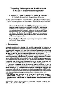
4. Testbed Our experimental testbed is comprised of three robots— a crane, a roving eye and a mobile manipulator (Figure 2). The crane, called Robocrane, is a 20-foot high, inverted Stewart platform built by the National Institute of Standards and Technology (NIST) [1]. Robocrane consists of a large triangular platform supported by six cables attached to winch motors. This enables Robocrane to move freely with six degrees of freedom in a roughly 10 foot cubed workspace. We have added a winch motor on the platform, which pays out a cable to which an 8-foot long beam is attached. The roving eye is the robot Xavier, a 4-foot tall, 2-foot diameter synchro-drive robot with stereo cameras mounted on a pan-tilt head [17]. The mobile manipulator is built on top of a four wheeled robot testbed, called Bullwinkle, which can drive and avoid obstacles using stereo vision [19]. The manipulator itself, which mounts to the front of Bullwinkle, is a 5 DOF arm designed and built at NASA Johnson Space Center. The end effector is an electromagnet mounted on springs at the end of the wrist and is used to attach to the underside of the hanging beam. The three robots communicate with each other and an off-board workstation using Wavelan radio Ethernet.
Figure 2. Experimental testbed consisting of 6 DOF crane, mobile manipulator, and roving eye robots.
5. Distributed Coordination To perform large-scale assembly tasks, the robots must coordinate their actions. For instance, the crane and the mobile manipulator must coordinate so the manipulator has enough freedom to move the beam without having to support much of the beam’s weight. Similarly, the roving eye and crane must coordinate so that the position of the beam can be well estimated. Our approach to the problem of distributed coordination extends work we have done in single robot task-level control [16],[18]. The basic idea is that agents execute plans by dynamically constructing task trees. Nodes in a task tree represent com-
mands (which are primitive behaviors executed by the robot), goals (which are further decomposed into subgoals and/or commands), or monitors (which are periodically executed). Tasks within the tree are partially ordered, with temporal constraints between them. For instance, one can constrain goal B to start after goal A ends, which implies that no subtask of B can start until all the subtasks of A have completed. Tasks can also raise exceptions and terminate other tasks. Temporal constraints and goal decomposition strategies are encoded using the Task Description Language (TDL), a superset of C++ that has explicit syntax to support creating tasklevel control programs [18]. For this work, we are extending TDL to deal with synchronization of multiple agents. The idea is to distribute the task tree representation so that each of the robots maintains only a part of the complete tree (that portion dealing with their own goals and actions). Temporal constraints can be associated between nodes on different robots. For instance, one can encode that task A on robot 1 must start 10 seconds after task B on robot 2 starts. The extensions made to TDL also enable robots to monitor each other’s execution, handle exceptions raised by others, and terminate tasks of other agents. The multi-agent version of TDL forms an infrastructure for coordination— it allows expression of the necessary synchronization constraints. However, it does not address what coordination needs to take place to do the task. This is the responsibility of the planning layers. Consider, for instance, the following scenario for the task of connecting a beam at a given location: A call is put out for a foreman to manage this task, which could be filled by an agent that has sufficient knowledge and available computational resources. The chosen foreman would put out a request for an available crane, a roving eye or two and, possibly, a mobile manipulator, depending on the precision needed for the particular task at hand. Agents can participate in more than one task— for instance, a roving eye with a pan-tilt head could conceivably assist in two different assembly subtasks, if they are within proximity. Once a team is chosen and roles assigned, the agents coordinate amongst themselves. For instance, the roving eye and the crane coordinate to exchange information, and the crane and mobile manipulator coordinate to decide which will move when, and by how much. While the scenario described above illustrates our longer-term goals for multiagent coordination, our current implementation uses a fixed set of three robots, a fixed “foreman” agent, and fixed task assignments (Figure 3). The foreman agent decides which robot should be moving the beam at which times. It initially tasks the crane to move the beam to the vicinity of the emplacement point, which the crane does based solely on encoder feedback. This gets the fiducials on the beam within the roving eye’s field of view. The foreman then sets up a behavioral loop between the roving eye and crane robots to servo the beam to near the emplacement point (Section 6). The foreman monitors the progress and, when the difference between the desired and observed poses of the fiducials is within the resolution of the crane’s motion, it tasks the roving eye and the mobile manipulator to servo the arm to grasp the beam. When the arm indicates that it is in contact with the beam, the foreman initiates the task of having the roving eye and mobile manipulator coordinate to servo the beam to the emplacement point, which completes the task. The foreman also handles some
Crane Roving Eye
(tracking, positioning)
Foreman
future
Mobile Manipulator
Figure 3. Robot agents for the assembly task. Agents can communicate directly with each other, or through a foreman agent. In the future, the crane and mobile manipulator will be able to negotiate directly with each other.
simple task failures. For instance, if the arm loses contact with the beam, the foreman restarts the arm-grasp-beam task. In the near future, if the mobile manipulator finds itself at the limits of its workspace, it will negotiate directly with the crane robot to provide it more slack on the beam.
6. Distributed Visual Servoing An important step in our research has been to develop a technique for distributed visual servoing. The roving eye uses a pair of cameras to track fiducials that are placed on the beam, the mobile manipulator arm, and the destination site (Figure 4).
Figure 4. Tracking fiducials by the roving eye robot (left). Fiducials (right) are mounted on the fixed structure, on the beam being emplaced, and on the mobile manipulator.
The roving eye moves in order to maintain the best view of the fiducials. It pans and tilts the cameras and drives around the workspace to keep the targets in sight and centered in the image, and it moves back and forth to ensure that the targets fill most of the cameras’ fields of view. Stereo is used to compute the 6 DOF pose of each object marked with fiducials, and the differences between the poses of the objects are used to compute manipulator motion commands. Figure 5 illustrates the data flows between modules. The visual servoing runs as a set of distributed behaviors, implemented using the Skill Manager from the 3T architecture [3]. Information flow between modules is implemented using message passing.
behavior control
Visual Tracking
Motion Hints
6DOF pose differences
Executive
Manipulation Manager
Crane 6DOF motion commands
Foreman Roving Eye Behaviors
Arm
Roving Eye
Figure 5.
Data flow between the distributed visual servoing modules.
6.1. Servo Control The roving eye needs to communicate to the crane and mobile manipulator how to move the beam in order to position it properly. Since none of the robots knows anything about the others’ positions, they must communicate information solely in terms of the task space (i.e., the relationship between the beams, or the beam and the arm). The Manipulation Manager module (a component of the “foreman” agent) is used to perform geometric transformations between task space and manipulator space. It uses the pose differences between the objects, combined with knowledge of goal positions, to compute the end-effector motion needed. This motion transform is sent to the appropriate robot agent, which uses its own kinematic model to determine how to move to achieve the desired transform. The servoing process starts with the roving eye providing information to the crane. It continues until the crane is close enough to the destination, where “close enough” is based on how accurately the crane can be expected to move the beam and how close the beam must be before the arm can grasp it for the final positioning. After the crane moves the beam close to the goal position, the arm is visually servoed to grasp the beam. The grasping motion of the arm works similarly to the crane motion. The roving eye tracks the end-effector of the arm and the horizontal beam held by the crane. The Manipulation Manager computes desired end-effector motion from this combined with knowledge of the desired grasp point on the beam. The arm motion uses a dynamic look-then-move scheme, in which position commands are given to the arm, but they can be interrupted by new ones before they complete. This allows for smooth arm motion combined with the safety that the arm will stop if it does not receive new motion commands for some reason. This servo loop stops when the gripper (an electromagnet) contacts the beam and sticks to it. In the final phase of the task, the arm moves the beam to dock with the stationary beam. The grasped beam hangs from the crane by a cable, which provides compliance but also complicates motion since the arm does not have full control of the beam. It can effectively control only the position of the end of the beam, but not its orientation. In addition, if the angle between the beam and the arm’s end-effector is too large, the magnet will not be able to hold the beam. Therefore for this subtask the roving eye tracks three objects: the positions of the stationary beam, the moving
beam, and the arm end-effector. The Manipulation Manager computes end-effector motions which will move the end of the beam to the correct position while keeping the angle of the end-effector matched to the angle of the grasped beam. This servo loop stops when the end of the moving beam has been placed into a slot atop the fixed beam. This currently operates with about 5mm accuracy in the placement of the hanging beam. The visual servoing runs as a set of behaviors distributed over the robots. The roving eye continually tracks the fidicuals (at about 3 Hz) and the Manipulation Manager calculates motion commands for the crane or the arm, as appropriate. The crane and the arm each obey these commands as often as they can. The crane can not yet move continuously, so it makes discrete moves one at a time, ignoring new commands until the previous one finishes. The arm can move continuously, so it adjusts its motion with every new command. An executive module implemented using TDL (a part of the Foreman), manages the process by starting, monitoring, and stopping these behaviors. The bar coded fiducials used on the beams allow unique identification of several fiducials (8 in the current scheme), and is quite robust to background noise. The tracking starts with an adaptive threshold, to correctly separate black and white even if some fiducials are in shadow and some in strong light. Next, connected components are found which have the same centroids, thus picking out the “bullseyes” on each end of each fiducial. Each pair of bullseyes are used as the endpoints for a bar code scan line, and the pairs with valid bar codes between them are kept as fiducials. 3D data is found by triangulating the positions of the corners of the bullseyes and fitting a model of the object’s fiducials to this sensed data. 6.2. Roving Eye Motion Control of the roving eye motion is accomplished with three behaviors: panning to keep the fiducials centered in the images, moving forward or backward to keep the cameras as close as possible to the fiducials, and lateral motion to move to face the fiducials as directly head-on as possible. Running concurrently, these behaviors keep the roving eye directly in front of the fiducials and close enough to see them well, but not so close that they are in danger of moving outside the field of view of the cameras. The behaviors are diagrammed in Figure 6 (a) and the resulting motion is depicted in Figure 6 (b). The roving eye behaviors receive information from the vision system in the form of “eye motion hints”. These consist of the bounding box of the fiducials in the images and the average angle of the surface normals relative to the camera pointing angle. The bounding box of the fiducials is used by the panning behavior to keep the edges of the fiducials as far as possible from the edges of both fields of view simultaneously. This bounding box is also used by the forward motion behavior that drives the roving eye towards or away from the fiducials. If any side of the bounding box is too close to the edge of the frame, the roving eye backs away. If all sides are too far from the edges of the frame, it drives forward. The lateral motion behavior uses the average of the fiducial surface normal angles projected onto the ground plane. It moves the robot left or right to be most directly in front of the fiducials. This is
Zoom to fill frame
Vector sum
Move to face targets squarely
(a)
(b)
Pan to center targets
Figure 6. (a) The three motion behaviors of the roving eye robot. (b) The resulting motion of the roving eye.
important since the fiducials are planar: when viewed from an angle that is too steep, tracking will fail. The three roving eye behaviors combine to produce smooth motion when the vision updates are fast enough relative to the driving speed of the roving eye. Figure 6 (a) shows how the lateral motion and forward motion behaviors’ outputs are combined in a vector sum. These vectors are defined relative to the orientation of the cameras so that when the panning behavior turns the cameras, the directions of the vectors from the other behaviors change accordingly. Lateral robot motion moves the fiducials off-center in the images, triggering the panning behavior. Together these two effects generate smooth motion in a spiral arc.
7. Conclusions We have demonstrated preliminary results for the coordination of a team of heterogeneous robots performing an assembly task. The roving eye provides higher servoing accuracy more consistently for a larger workspace than a fixed camera system. The roving eye has greater robustness to tracking failures because of its ability to stay aligned with the fiducials. Accurate camera calibration has not been necessary because visual servoing provides relative positions of the fiducials— errors due to calibration affect all measurements roughly equally. Currently, our implementation with a Manipulation manager falls short of the ideal distributed three layer architecture (Figure 1). In the near future, we will distribute the functionality of the Manipulation Manager amongst the behavioral layers of the multiple agents to remove a bottleneck from the high bandwidth behavior-level communication. In this scenario, each robot will be more autonomous as well, since each will calculate its own motion rather than being commanded by the Manipulation Manager.
Acknowledgements This research was sponsored in part by a grant from NASA (NAG9-1226). The robot arm used on the mobile manipulator was developed by Metrica under a NASA grant. Josue Ramos was funded by a grant from CNPq-Brazil (200501/86-0).
References [1] J. Albus, R. Bostelman, N. Dagalakis, 1992 The NIST ROBOCRANE, Journal of Robotics System, 10:5. [2] R. Arkin, 1992 Cooperation without Communication: Multiagent Schema-Based Robot Navigation, Journal of Robotic Systems, 9:3, pp. 351-364. [3] P. Bonasso, D. Kortenkamp, D. Miller, M. Slack, 1997 Experiences with an Architecture for Intelligent, Reactive Agents, Journal of Artificial Intelligence Research, 9:1. [4] M.B. Dias, A. Stentz, 2000 A free market architecture for distributed control of a multirobot system, In Proc. 6th International Conference on Intelligent Autonomous Systems (IAS6), pp 115-122. [5] L. Chaimowicz, T. Sugar, V. Kumar, and M. Campos 2001 An Architecture for Tightly Coupled Multi-Robot Cooperation , in Proceedings International Conference on Robotics and Automation, Seoul, Korea, May 21-26. [6] B. Donald, 1995 Distributed robotic manipulation: experiments in minimalism, In: Proc. International Symposium on Experimental Robotics (ISER), Springer-Verlag, pp 11-25. [7] D. Hershberger, R. Burridge, D. Kortenkamp, R. Simmons, 2000 Distributed Visual Servoing with a Roving Eye, In Proc. Conference on Intelligent Robots and Systems (IROS), Takamatsu Japan, October. [8] N.R. Jennings. 1993 Specification and Implementation of a Belief-Desire-Joint-Intention Architecture for Collaborative Problem Solving, International Journal of Intelligent and Cooperative Information Systems, 2(3), pp. 289-318. [9] J. Jennings, C. Kirkwood-Watts, 1998 Distributed mobile robotics by the method of dynamic teams, In Proc. Conference on Distributed Autonomous Robot Systems (DARS). [10] O. Khatib, 1995 Force Strategies for Cooperative Tasks in Multiple Mobile Manipulation Systems, In Proc. International Symposium of Robotics Research, Munich, October. [11] M. Mataric, 1992 Distributed Approaches to Behavior Control, In Proc. SPIE Sensor Fusion V, pp. 373-382. [12] N. Muscettola, P. P. Nayak, B. Pell, and B. Williams, 1998 Remote Agent: To Boldly Go Where No AI System Has Gone Before, Artificial Intelligence 103(1-2), pp. 5-48, August. [13] L. Parker, 1998 ALLIANCE: An Architecture for Fault Tolerant Multirobot Cooperation, IEEE Transactions on Robotics and Automation, 14:2, pp. 220-240, April. [14] T. Sandholm, O. Shehory, M. Andersson, K. Larson, and F. Tohm , 1998 Anytime Coalition Structure Generation with Worst Case Guarantees, In Proc. Fifteenth National Conference on Artificial Intelligence (AAAI), pp. 46-53, Madison WI, July. [15] O. Shehory O, S. Kraus,1998 Methods for task allocation via agent coalition formation, Artificial Intelligence Journal, 101:1-2, pp 165-200, May. [16] R. Simmons, 1994 Structured Control for Autonomous Robots, IEEE Transactions on Robotics and Automation, 10:1, pp 34-43, February. [17] R. Simmons, R. Goodwin, K. Haigh, S. Koenig, J. O Sullivan, 1997 A Layered Architecture for Office Delivery Robots, In Proc. First International Conference on Autonomous Agents, Marina del Rey, CA, February. [18] R. Simmons and D. Apfelbaum, 1998 A Task Description Language for Robot Control, In Proc. Conference on Intelligent Robotics and Systems, Vancouver Canada, October. [19] S. Singh, R. Simmons, T. Smith, A. Stentz, V. Verma, A. Yahja, and K. Schwehr, 2000 Recent Progress in Local and Global Traversability for Planetary Rovers In Proc. International Conference on Robotics and Autonomous, San Francisco CA, April. [20] R. Smith, 1980 The contract net protocol: high-level communication and control in a distributed problem solver, IEEE Transactions on Computers, C-29:12, pp 1104-1113, [21] K. Sycara and D. Zeng, 1996 Coordination of Multiple Intelligent Software Agents, International Journal of Cooperative Information Systems, 5:2-3. [22] M. Tambe, 1997 Towards Flexible Teamwork, Journal of Artificial Intelligence Research, No. 7, pp. 83-124.