FLEXIBLE PROTECTION ARCHITECTURES USING DISTRIBUTED OPTICAL SENSORS P. Orr1, G. Fusiek1, C.D. Booth1, P. Niewczas1, A. Dyśko1, F. Kawano2, P. Beaumont2, T. Nishida3 1
Institute for Energy and Environment, University of Strathclyde, Glasgow, UK,
[email protected] 2 Toshiba International (Europe), UK,
[email protected] 3 Toshiba Corporation, Japan,
[email protected]
Keywords: NCIT, passive, optical, distributed protection, wide-area.
immune to electromagnetic interference, and able to be interrogated over long distances [5].
Abstract
Optical current transducers (OCTs) are now relatively well established and are developed by a range of manufacturers for their passive and highly accurate measurement of electrical current [6,7]. The common design is based on either spun or annealed optical fibre (to reduce shape-induced linear birefringence) that is coiled around the conductor or current path. The contour integral of the circulating magnetic field around the conductor then yields a polarimetric or interferometric measurement of enclosed current based on the Faraday effect [8]. Optical voltage transducers (OVTs) have also been developed, primarily based upon either the electrooptic (Pockels) effect or the piezoelectric effect [7,9]. Both conventional OCTs and OVTs rely on interferometric or polarimetric measurement techniques, and thus the distance from interrogator to measurement point cannot be greater than around 100 metres. Additionally, similarly to conventional electrical transducers, it is not possible to discriminate between superimposed sensor responses and thus serial multiplexing is not possible. For these reasons, wide-area coverage, measurement over long distances, and high numbers of sensors are not presently achieved by optical current or voltage measurement schemes.
In this paper we describe recent developments in flexible protection schemes that make use of passive fibre Bragg grating (FBG) based transducers for the distributed measurement of voltage and current. The technology underpinning the passive optical approach is described in detail, and both the present development and the future potential of the approach are discussed. In co-operation with Toshiba, the integration of the technique with an existing busbar protection relay is demonstrated, illustrating the flexibility offered by protection schemes that are based on the use of small, passive, multiplexable, dielectric transducers.
1 Introduction Conventional unit type protection schemes rely on the communication of measured currents and/or voltages between relays at different locations. In most cases this continuous communication of sampled values, phasors, or Boolean flags is transmitted digitally using optical fibre [1]. In this configuration, the protection relays are always situated close to the measurement points, and additional relays are required for non-local measurements. Differential schemes based on this historical approach are therefore limited in flexibility and extensibility by the communication bandwidth, the requirement for local power at each measurement point, and the size, weight and insulation requirements of conventional transducers. The latency of the communications link and the requirement to encode and decode the communicated data can also result in the communications system contributing to an increase in the operating time of the protection system. Optical sensing is an established technology that provides solutions to a number of measurement problems posed by adverse environmental conditions, such as those commonly encountered in the oil and gas sector, nuclear industry and electrical power generation and distribution [2–4]. In many cases, conditions in these environments are such that conventional electronic sensors cannot operate to the required standards. Fibre-optic sensing is a high-performance measurement technology incorporating transducers and sensor networks that are passive, compact, chemically inert,
In this paper, we describe a scheme for optical measurement of voltage and current that is based on in-fibre point sensors. The proposed sensors are physically small and are able to be multiplexed, thus overcoming problems with conventional optical schemes and allowing the implementation of novel protection architectures that are not achievable with present electrical or optical sensing schemes. Such an approach has the potential to address the limitations of standard protection architectures by presenting, at a single point, information on voltage and/or current from multiple widespread locations on a network. As a proof of concept, we report on the integration of this measurement scheme with a Toshiba busbar protection relay. Additionally, we discuss the potential of the approach to address the protection challenges of the future.
2 Optical Measurement of Current and Voltage Current transducers may be classified [10] as: conventional, i.e. utilising resistive shunts or iron core or Rogowski type
transformers; pure optical based on the Faraday effect as described above; or extrinsic optical. It is the latter category that is proposed here, where an intermediate transducer is used to convert current into a secondary quantity – often strain – that is measurable by the chosen all-optical transducer.
It was demonstrated previously that these fibre-optic voltage and current sensors can be used for measuring variable frequency voltage and current waveforms for use in future aero-electric power systems [16]. Their use in simplified differential and distance protection schemes (implemented within the sensor interrogation unit) has also been reported previously in a preliminary form [17,18].
2.1 Fibre Bragg Gratings (FBGs) Fibre Bragg gratings (FBGs) are periodic perturbations of the refractive index along a fibre core, having peak optical reflection at a specific wavelength, known as the Bragg wavelength [11], and a physical length of ~10 mm. In sensor applications, their wavelength-encoding nature coupled with their simple reflected spectra mean that FBGs are relatively easy to interrogate and multiplex, and are effectively immune to the problems of intensity fluctuations and attenuation [3]. For these reasons the FBG is now ubiquitous in the field of optical instrumentation [4,12]. Peak optical reflection from FBGs is experienced where the wavelength λ is equal to twice the grating period, i.e. at λ/n = 2Λ where n is the fibre refractive index and Λ is the grating pitch. Thus, straining the fibre longitudinally at the location of the grating redshifts the peak reflected wavelength. Illumination of the FBG by broadband light, and some form of peak wavelength detection and tracking, may therefore be employed to utilise the FBG as a sensor for strain.
2.3 Sensor Network Topology and Interrogation The generic architecture of an FBG sensor scheme is illustrated in Figure 2. Light from an optical source is guided by fibre to the array of serially-multiplexed FBGs. Reflections from all FBGs are returned via a coupler to the interrogating device, at which the peak reflected wavelength from each sensor is extracted.
Figure 2: A generic FBG measurement scheme illustrating the multiplexed and reflection-mode topology. λ1 and λ2 are peak reflected wavelengths. In this work, we utilise a long-distance multiplexing FBG interrogator developed by Strathclyde for the monitoring of subsea electrical submersible pumps (Figure 3) [5].
2.2 FBG-Based Voltage and Current Sensors The authors have previously developed fibre-optic point sensors for both voltage and electrical current, based on FBG technology, that have been applied successfully to power system plant diagnostics [13,14]. The complete optical sensor system has been shown to be capable of measuring dynamically changing signals and has been successfully used for detecting higher order voltage and current harmonics [15].
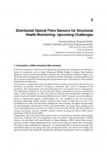
b) Burden Resistor
FBG
a) Piezoelectric Stack E
~ i Conductor
Current Transformer
Figure 1: a) Hybrid voltage sensor; b) Current sensor employing a voltage sensor and a current transformer. The hybrid voltage sensor employed in this work utilises an FBG bonded to a multilayer piezoelectric stack, while the current sensor uses a small, high-bandwidth current transformer monitored by a dedicated voltage sensor as shown in Figure 1. In both cases an FBG peak wavelength shift can be calibrated in terms of voltage or current, while for ac voltages or currents, a temperature measurement can also be performed simultaneously using the same sensors.
Figure 3: Scanning filter based FBG interrogator. SFS is broadband optical source. In this scheme, a tunable filter is scanned over the bandwidth of the source and the photodetector output is sampled continuously. Extraction and tracking of FBG peaks is performed in software based on the recorded spectra. It should be noted that alternative interrogation schemes may be used. In general, present interrogation schemes possess a trade-off between the extensibility (number of sensors) and the performance (rate, accuracy, resolution). However, recent schemes are beginning to address this [19].
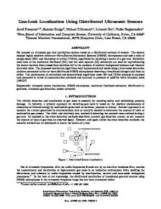
A
B Ip1
Ip2 I1
FBG Relay 1
Singlemode fibre
I2
FBG Relay 2
To next sensors
To interrogator/relay Interrogation system
Analog
PXI (A/D)
Digital
Transceiver unit
Optical link GRB100
PC (LabVIEW)
Figure 4: Illustration of processing and subsystems in an extensible differential protection scheme based on the optical/GRB100 hybrid scheme.
3 Integration with Toshiba GRB100 CU
3.2 Real-Time Current Measurement Performance
In order to demonstrate the integration of multiplexed optical current measurement with protection hardware, the measurement scheme described above was configured to emulate the output of a Toshiba GRB100 bay unit [20]. The hybrid system was then tested successfully with real-time measured currents.
In order to verify the correct functioning of the communication interface, ac currents were applied to three optical current sensors simultaneously. The waveforms, as recorded by the optical scheme and on the GRB100 disturbance records, were then compared directly.
3.1 Implementation of GRB100/Optical Hybrid In order to facilitate communication between the optical measurement scheme and the GRB100, Toshiba’s bespoke communication protocol for interfacing between the relay central unit (CU) and associated bay units (BUs) was implemented within the optical measurement scheme. This allowed for direct communication with the GRB100 central unit by emulation of the BU output format. The optical scheme thus behaves as a BU by delivering sample-by-sample data relating to the three measured currents in the expected format. With reference to Figure 4, which illustrates data flow in the scheme, two multifunction National Instruments PXI cards were used. This permitted acquisition of signals from three optical current sensors and realisation of data communication between the optical system and the GRB100 CU. The optical sensors were interrogated by a bespoke interrogation system and a PXI-6259M card was used to acquire and generate signals required for the interrogation unit control. The card sampling rate was adjusted such that 48 samples per period of the current waveform were acquired in accordance with the GRB100 protocols. After coding the data in the expected format, current samples for all phases are transmitted via an optical transmitter following the receipt of each synchronisation signal from the GRB100 CU. In this way, the optical scheme emulates a GRB100 bay unit and delivers data in the expected format. It should be noted that although this preliminary scheme delivers three current measurements to the protection relay, future development of the hybrid optical scheme will focus on delivering large numbers of measurements originating from different system locations to an appropriate protection device in order to realise the full potential of the optical approach.
Figure 5 illustrates the test configuration adopted. The scheme incorporates the interrogation scheme of Figure 3, with the addition of three fibre-optic current sensors, synchronous output to a GRB100 CU, and an APTS3 current injection unit [21]. A function generator was used to generate current waveforms to be driven through each CT primary winding. The optical scheme records all sensor responses simultaneously. After interrogating for current, the three currents are treated as phases A–C of a three-phase scheme and the data is packaged appropriately for quasi-synchronous transmission to the GRB100. As described in the previous section, 48 samples per cycle are acquired and thereafter transmitted within the sampling intervals.
Figure 5: Three-phase single-fibre laboratory test scheme using APTS3 current injection unit. λ1-3 are sensor Bragg wavelengths, RB1-3 are burden resistors, BBS is broadband optical source, SFP is scanning optical filter. Current testing was performed with and without the 24 km link of single-mode fibre shown in Figure 5. Figures 6 and 7 represent situations where measurements were taken locally,
while Figures 8 and 9 were recorded at a full distance of 24 km from interrogator/relay to the three sensors.
Current measurement performance is clearly superior for the local sensors (as opposed to the remote sensors) in terms of current resolution. It is clear that using the present optical measurement scheme, sensors operating at a distance (in this instance 24 km) are subject to increased attenuation, resulting in larger errors in interrogation. This can be readily corrected in future iterations of the scheme by adjusting photodetector gains or source output power.
4 Novel Protection Applications and Topologies
Figure 6: Simultaneous local measurement of three phase currents (in phase) as recorded by the optical scheme (black) and fault record (red).
The main attraction and differentiator of this approach from both conventional electrical and optical techniques is that both currents and voltages can be acquired passively from multiple (potentially >100) widely-spaced locations and made available simultaneously at an interrogation point. This presents possibilities for extremely fast (and possibly singlerelay) differential/distance protection schemes without the need for additional dedicated communications channels for data transfer and/or to enhance the speed of operation. Building on this unique capability, a number of key applications for this technology may be proposed. 4.1 Protection of Hybrid OH/UG Lines
Figure 7: Detail of local Phase C waveforms during current build up. A constant offset of 2 A is applied to the optical waveform (black) for clarity.
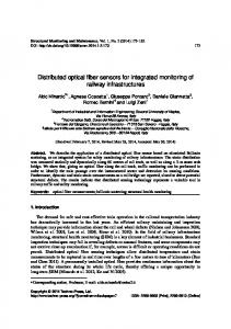
Figure 8: Measurement at 24 km of Phase C current as recorded by the optical scheme (black) and GRB100 fault record (red).
Figure 9: Detail of 24 km Phase C waveform during current build up. A constant offset of 2 A is applied to the optical waveform. It is clear that there is excellent agreement between waveforms either side of the communication interface. Small “smoothing” differences can be seen in the GRB100 waveforms: this is due solely to input signal filtering. It should be noted that a comparison of the optical and relay waveforms must take into account the digital filtering, which reduce the noise components in the GRB100 disturbance records compared with the raw measurement waveforms.
In certain network locations, hybrid lines exist comprising a mixture of overhead line and underground cable. From a protection standpoint, it is desirable to attempt re-closure of the breaker after the fault has cleared if the fault lies on the overhead line, but not if the fault lies on the underground section. In present protection schemes, it is not possible to discriminate which section of a hybrid line is subject to the fault, and to install additional measurement and protection devices at the cable terminals would be costly and impractical.
Figure 10: Optical multi-differential relay for protection of hybrid circuits comprising overhead line (OHL) and underground cable (UGC). On this basis, an optical fibre multi-differential relay could be developed that would provide passive current measurement at multiple locations along the hybrid line, including at cable terminals (Figure 10). In this way, the relay would be able to determine, with a high level of discrimination, which section of the line is affected by the fault and could initiate (or inhibit) re-closure accordingly. 4.2 Multi-Terminal Protection – Faster and Simplified The requirement in present protection architectures for the continual communication of measured values or Boolean flags between co-operating relays is most evident in multiterminal networks. As illustrated in Figure 11, since each relay is measuring independently, their tripping states must be
communicated to all other relays for effective operation of the overall protection scheme. Compared to the centralised, passive optical approach, this architecture is expensive and convoluted (see Figure 11), requiring many relays and dedicated communication channels. There is clear justification in this instance for development of a centralised protection.
Figure 11: A multiple terminal network, illustrating the timeintensive circuital communications architecture of the standard protection scheme. 4.3 UHV Transformer Protection Protection for UHV transformers (involving primary, secondary and tertiary windings) is extensive and complex due to the requirement for multiple measurement points [22]. As an example, UHV transformers can often incorporate 40– 50 transducers (CTs and VTs) which must deliver measurements to the protection relay(s). The use of smaller, isolated transducers for this purpose is desirable. In particular, the optical scheme’s flexibility to multiplex all transducers on a single or multiple fibres would be highly convenient. Additionally, FBG sensors are capable of measuring secondary parameters such as temperature, vibration, and pressure [4]. A single “protection and monitoring” scheme could be developed on this basis, delivering full electrical and mechanical coverage of these large, valuable items of plant. 4.4 Wide-Area Backup Protection Due to their capability for long-distance (>100 km) interrogation, FBG sensor schemes will be eminently suitable for the wide-area backup protection of multiple areas on a large network (Figure 12). Monitoring and protection based on voltage and current measurements taken at multiple locations will be possible from a single central location.
4.5 Fibre-enabled Synchrophasors (Without GPS) Presently, phasor measurement units (PMUs) require use of the GPS network to accurately time-stamp voltage or current measurements for direct comparison of phasors at diverse locations on the network [23]. Access to the GPS radio clock is required primarily because otherwise it is not possible to synchronise measurements that are taken by a variety of different measurement schemes at different locations. Alternatively, the precision time protocol may be applied to synchronise clocks on a network, but this requires infrastructure for continuous communication between all measurement devices [24]. Use of the long-distance passive fibre sensor network for voltage and/or current could facilitate synchrophasor measurement without the use of GPS, since in the optical scheme the relative delay between measurement points is measurable. A constant delay of approximately 4.9 μs/km (9.8 μs/km round trip) will exist between sensor reflections arriving at the interrogation unit, which can be corrected for at the central interrogator/relay. Since FBG interrogators can make measurements of a span of 100 km or more, there is potential for centralised wide-area synchrophasor coverage without a requirement for absolute time-stamping or access to the GPS network. 4.6 Centralised Management of Smart Grids At lower voltages, the possibility of having many measurements of current and voltage available at a single location presents opportunities for the development of new protection, control and monitoring systems that will be required for future “smart” grids or active networks. It is anticipated that these networks will connect to many distributed energy sources and storage devices; thus it will be critical that protection and control systems have visibility of voltages and current throughout the networks. The approach proposed here will be ideally suited to the provision of this information, since it is able to take voltage and current measurements from several locations simultaneously. As mentioned above, use of an all-fibre approach will eliminate the need for time stamping or dedicated communications networks, which would complicate and congest future networks as the density of required measurements increases.
5 Conclusions Central Unit – Protection Calculation Optical Fibre Optical Coupler
FBG sensors
A S/S
Superluminescent Diode: SLD
B S/S
Figure 12: FBG-enabled wide-area backup protection
In this paper we have proposed that established optical fibre measurement technology has excellent potential in improving present power system protection systems and meeting the protection demands of future networks. The key benefits of this technology compared with conventional electrical and existing optical techniques include passive sensing at a distance, single-fibre multiplexing, and reflection-mode operation, facilitating the development of novel schemes that are not achievable with conventional methods. The technology for voltage and current measurement using FBG-based sensors has been described, leading to a standard
system design for the centralised monitoring of voltage, current, and mechanical parameters. The integration of this measurement technology with a Toshiba GRB100 busbar protection relay has been reported, illustrating the immediate application of this technique to industry. The field implementation of any new technology in the safety critical power system protection domain requires a high level of resilience to failure. Therefore, it is recommended that future work in this area should focus on assessing and improving reliability (including the provision of redundancy for passive remote measurement), determining ratio and phase errors, delivering tripping, indication and other protection scheme logic signals using the same fibre, and improving the design of the voltage and current transducers with a view to size reduction and the reduction or removal of high-current saturation phenomena.
[11]
[12] [13]
[14]
[15]
Acknowledgements The authors acknowledge the funding and collaboration of Toshiba International (Europe) and Toshiba Corporation.
[16]
References [1] Phadke, A.G. and Thorp, J.S. (2009) Computer Relaying for Power Systems, Research Studies Press, London/John Wiley & Sons, Inc., New York [2] A. Moghadas, R. Barnes, M. Shadaram, “An innovative Fiber Bragg Grating sensor capable of fault detection in radial power systems,” Systems Conference, 2010 4th Annual IEEE , pp.165-168, 5-8 April 2010 [3] P. Niewczas, J. R. McDonald, “Advanced optical sensors for power and energy systems,” IEEE Instrumentation and Measurement Magazine, vol. 10, no. 1, pp. 18–28, February 2007 [4] A. D. Kersey et al, “Fiber Grating Sensors,” J. Lightwave Tech., vol. 15, no. 8, pp. 1442-1463, August 1997. [5] G. Fusiek, P. Niewczas, J. R. McDonald, “Extended Step-out Length Fiber Bragg Grating Interrogation System for Condition Monitoring of Electrical Submersible Pumps”, Optical Engineering, Vol. 44, No. 3, pp 034404-1-10, March 2005 [6] Alstom NXT Phase COSI Products, http://www.nxtphase.com (Accessed 24/01/2012) [7] K. Bonhert, P. Gabus, J. Kostovic, H. Brandle, “Optical fiber sensors for the electric power industry,” Optics and Lasers in Engineering (Elsevier), vol. 43, pp. 511–526, 2005. [8] Y. N. Ning, Z. P. Wang, A. W. Palmer, K. T. V. Grattan, and D. A. Jackson, “Recent progress in optical current sensing techniques,” Rev. Sci. Instrum., vol. 66, no. 5, pp. 3097-3111, 1995. [9] Pan, F., Xiao, X., Xu, Y., and Ren, S., “An Optical AC Voltage Sensor Based on the Transverse Pockels Effect,” Sensors (Basel) 11(7), 6593–6602 (2011) [10] J. Horak and J. Hrabliuk, “Current transformer errors and transformer inrush as measured by magnetic, optical
[17]
[18]
[19]
[20]
[21]
[22]
[23]
[24]
and other unconventional CTs,” Available from www.basler.com/downloads/CTerrors.pdf G. Meltz, W. W. Morey, W. H. Glenn, “Formation of Bragg gratings in optical fibers by a transverse holographic method,” Opt. Let., vol. 14, no. 15, pp. 823–825, August 1989. A. Mendez, “Fiber Bragg grating sensors: a market overview,” Proc. SPIE, vol. 6619, p. 661905, 2007. L. Dziuda, P. Niewczas, G. Fusiek, J. R. McDonald, “Hybrid Fiber-Optic Voltage Sensor for Remote Monitoring of Electrical submersible Pump Motors”, Optical Engineering, Vol. 44, No. 6, pp 64401-1-6, June 2005 L. Dziuda, G. Fusiek, P. Niewczas, G. Burt, and J.R. McDonald, “Laboratory Evaluation of the Hybrid FiberOptic Current Sensor”, Sensors and Actuators, A: Physical, Vol. 136, No. 1, pp. 184-190, May 1, 2007 P. Niewczas, G. Fusiek, J. R. McDonald, “Dynamic capabilities of the hybrid fiber-optic voltage and current sensors”, IEEE Sensors Conference, Daegu, Korea, Oct. 22-25, 2006 G. Fusiek, P. Niewczas, J. R. McDonald, “Concept Level Evaluation of the Optical Voltage and Current Sensors and an Arrayed Waveguide Grating for AeroElectrical Systems’ Applications”, the 24th IEEE IMTC 2007 Instrumentation and Measurement Technology Conference, Warsaw, Poland P. Orr, P. Niewczas, A. Dysko, C. Booth, "FBG-based fiber-optic current sensors for power systems protection: Laboratory evaluation," Universities Power Engineering Conference (UPEC), 2009 Proceedings of the 44th International , pp.1-5, 1-4 Sept. 2009 P. Orr, P. Niewczas, A. Dysko, C. Booth, F. Kawano, G. Baber, “Distributed optical distance protection using FBG-based voltage and current transducers,” IEEE Power and Energy Society General Meeting, pp. 1-5, 2429 July 2011 P. Orr and P. Niewczas, “High-speed, solid-state, interferometric interrogator and multiplexer for fiber Bragg grating sensors,” J. Lightwave Tech., vol. 29, no. 22, Nov 2011 GRB100 Busbar Protection, http://toshiba.co.jp/sis/en/tands/protect/grb100.htm, Toshiba Corporation (Accessed 27/01/2012) ATPS3 Protection Relay Test Set, http://www.relayeng.com/apts/apts.htm, Relay Engineering Services Limited (Accessed 27/01/2012) X. Tang, K. Kobayashi, Y. Sonobe, M. Okazaki, A. Morimoto, P. Beaumont, “Development of 765kV Transformer Protection Relay,” Proc. Advanced Power System Automation and Protection, 2011. I. Hall, P. G. Beaumont, G. P. Baber, I. Shuto, M. Saga, K. Okuno, H. Uo, “New line current differential relay using GPS sycnhronization,” Proc. IEEE Power Tech Conference, Bologna, p. 8, June 2003 A. Carta, N. Locci, C. Muscas, “A PMU for the Measurement of Synchronized Harmonic Phasors in Three-Phase Distribution Networks,” IEEE Trans. Instr. and Meas., vol. 58, no. 10, pp. 3723–3730, Oct 2009