Proceedings of the SPIE Defense and Security Symposium, Unmanned Ground Vehicle Technology VI (OR54), Orlando FL, 12-16
FLEXnav: A Fuzzy Logic Expert Dead-reckoning System for the Segway RMP Lauro Ojeda1, Mukunda Raju2, and Johann Borenstein 3 1,2,3)
The University of Michigan Advanced Technologies Lab 1101 Beal Ave, Ann Arbor, MI 48108 3 Ph.: 734-763-1560 (POC) 1
[email protected];
[email protected];
[email protected]
ABSTRACT Most mobile robots use a combination of absolute and relative sensing techniques for position estimation. Relative positioning techniques are generally known as dead-reckoning. Many systems use odometry as their only deadreckoning means. However, in recent years fiber optic gyroscopes have become more affordable and are being used on many platforms to supplement odometry, especially in indoor applications. Still, if the terrain is not level (i.e., rugged or rolling terrain), the tilt of the vehicle introduces errors into the conversion of gyro readings to vehicle heading. In order to overcome this problem vehicle tilt must be measured and factored into the heading computation. A unique new mobile robot is the Segway Robotics Mobility Platform (RMP). This functionally close relative of the innovative Segway Human Transporter (HT) stabilizes a statically unstable single-axle robot dynamically, based on the principle of the inverted pendulum. While this approach works very well for human transportation, it introduces as unique set of challenges to navigation equipment using an onboard gyro. This is due to the fact that in operation the Segway RMP constantly changes its forward tilt, to prevent dynamically falling over. This paper introduces our new Fuzzy Logic Expert rule-based navigation (FLEXnav) method for fusing data from multiple gyroscopes and accelerometers in order to estimate accurately the attitude (i.e., heading and tilt) of a mobile robot. The attitude information is then further fused with wheel encoder data to estimate the three-dimensional position of the mobile robot. We have further extended this approach to include the special conditions of operation on the Segway RMP. The paper presents experimental results of a Segway RMP equipped with our system and running over moderately rugged terrain.
1. INTRODUCTION Proprioceptive position estimation (PPE), more commonly known as dead-reckoning, is widely used for measuring the relative displacement of mobile robots. Many conventional high-end dead-reckoning systems for ground-vehicles (typically, mobile robots) appear to be implemented according to a common approach: A 6-axes INS is fused with odometry using a Kalman Filter technique. Kalman Filters use statistical error models [Tonouchi, et al., 1994; Krantz and Gini, 1996, Baumgartner et al, 2001] to predict the behavior of sensor components. We believe that this approach is not ideal for odometry, because the statistical models can’t represent well single “catastrophic” events – and the encounter of a large bump or rock is indeed catastrophic for an odometry-based system. For many years the University of Michigan’s Mobile Robotics Lab has been developing an approach that favors indepth physical understanding of sensors and their associated error sources over the statistics-based Kalman Filter methods. Our basic philosophy is that many error mechanisms can be defined more specifically and accurately by expert reasoning. The result of our effort is a proprioceptive position estimation system called Fuzzy Logic and Expert rule-based navigation system (FLEXnav) [Ojeda and Borenstein, 2002]. The remainder of this paper is organized as follows. Section 2 describes our FLEXnav system in detail. Section 3 discusses the unique difficulties associated with the measurement of terrain pitch when using a dynamically balanced platform. Experimental results from our FLEXnav system implemented on our Segway RMP [SEGWAY] and driving over flat, horizontal terrain, as well as over moderately sloped terrain, are presented in Section 4.
CAN connector to host (user computer)
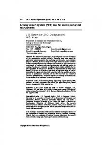
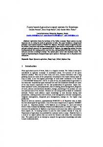
2. THE FLEXNAV SYSTEM A block diagram of the FLEXnav sensor suite is shown in Figure 1. The main inertial sensors are three single-axis fiber optic gyroscopes (FOGs) that measure rates of yaw, roll, and pitch; the two accelerometers are of lesser importance, and will be used to measure tilt on static conditions. The inertial sensors are mounted in an aluminum case on top of the Segway RMP as shown in Figure 2.
FLEXnav Dead-reckoning system PC-104 embedded computer To host, via CAN θ,Φ,Ψ Expert system
CAN Bus
attitude estimation CAN
CAN-toPC104 adapter
To θ,Φ,Ψ host, via CAN X,Y,Z Expert system
2.1 Attitude Estimation
Fiber-optic Gyro Group Gyro Roll Gyro Pitch Gyro Yaw
Accelerometer Group Y
position
The attitude of a robot is a set of three angles measured estimation X between the robot’s body and the absolute world coordinate From Host, via CAN CAN Bus X ,Y ,Z , θ ,Φ ,Ψ system. The term “navigation frame” is used for a world Pos. initialization, Odometry Real-time coordinate system, in which the x-axis points east, the y-axis self-calibration points north, and the z-axis is parallel but opposite in sign to the Accelerometer Slippage detection local gravity vector. Another coordinate system, called “body compensation frame,” can be thought of as embedded in the robot body. The From RMP via CAN body frame follows a prevailing convention used in ground encoder left & right vehicles for assigning the axes of coordinate systems, so that its xaxis points to the right, the y-axis points forward, and the z-axis Motor torque sensing points upward. Body axes are labeled xb, yb, and zb [Kelly, 1995], CAN connector to Segway RMP and the accelerometers and gyros described in this paper were mounted in alignment with these axes. Three angles express the Figure 1: Block diagram of the FLEXnav deadrelative orientation between the body frame and the navigation reckoning system for the Segway RMP. frame, as shown in Figure 3. 0
0
0
0
0
0
2003 DARPA MARS PPE for Segway.flo
The most common form of representation for these three angles is the so-called set of Euler angles, φ, θ and ψ. These three angles are called roll (sometimes also called “bank angle”), pitch (also called “elevation”), and yaw (also called “heading” or “azimuth”), respectively. φ Is the angle between xb and the horizontal plane after rotating clockwise the pitch axis yb through an angle θ (i.e., the plane that is normal to the z-axis of the navigation frame), θ is the angle between yb and the horizontal plane, and ψ is the angle between x and the projection of xb on the horizontal plane [Biezad et al., 1999]. For the mathematical treatment in the following sections we define a vector Λ = [φ, θ, ψ]T that will represent the Euler angles throughout this paper. Rates of rotation of the body frame relative to the navigation frame can be expressed in terms of the derivatives of the Euler angles, called “Euler rates.” Specifically, Euler rates Ωε and body rates of rotation Ω b are related by: T Ω ε = θ& φ& ψ& = C bε Ω b (1) where ⎡ ⎤ 0 sin φ ⎢ cos φ ⎥ Cbε = ⎢tan θ ⋅ sin φ 1 − tan θ ⋅ cos φ ⎥ ⎢ ⎥ sin φ cos φ ⎢ − ⎥ 0 Figure 2: The University of Michigan's Segway cos θ cos θ ⎣ ⎦
[
]
RMP with FLEXnav PPE system installed.
2
[
Ωb = ωx
ω y ω z ]T
ωx, ωy, and ωz are the rates of rotation of the vehicle around the respective axes of the body frame. Euler angles can be calculated from Euler rates by integrating Ωε over time: Λ = [θ
φ ψ ]T = ∫ Ωε dt
(2)
For many indoor mobile robotics applications, where floors are typically level, it is an acceptable and widely used assumption that φ and θ can be considered to equal zero. With this assumption we can rewrite Eq. 1:
ψ& = ω z
(3)
Table I: Technical specifications for the E-Core RA1100 and RA2100 fiber optic gyroscopes. (Courtesy [KVH]) Performance RA1100 RA2100 Input Rate (max) ± °/sec 100 100 Resolution °/sec N/A 0.014 Scale factor mV/°/sec 20 20 Nonlinearity %, rms 0.27% of distance traveled
9
a
b
Figure 11: Experiment on carpet. a. Trajectory. b. Return position errors.
Experiment 2: On asphalt (see Figure 12) Average speed 60 cm/sec; total travel distance: ~250 m AEE ccw: Xe = 90 mm; Ye = 888 mm => 0.35% of distance traveled AEE cw: Xe = 09 mm; Ye = 440 mm => 0.18% of distance traveled
b
a
Figure 12: Experiment on asphalt. a. Trajectory. b. Return position errors.
Experiment 3: On grass (somewhat rough ride) (see Figure 13) Average speed 50 cm/sec; total travel distance: ~55 m AEE ccw: Xe = 81 mm; Ye = 70 mm => 0.19% of distance traveled AEE cw: Xe = 76 mm; Ye = 182 mm => 0.36% of distance traveled
10
a
b
Figure 13: Experiment on grass. a. Trajectory. b. Return position errors.
4.2 FLEXnav on Segway: 3-D Terrain
In order to test the IR range sensor-based terrain estimation algorithm, we performed several experiments on smooth 3-D terrain. We started each run on flat terrain. We then steered the robot up an incline and then back down to the original position (see Figure 14a). This procedure was performed three times for each inclination (3, 6 and 9 degrees), after each experiment, the average pitch error was computed and compared with the true platform inclination (see Figure 14b). For each experiment we computed the terrain inclination based on the rear (βR), front (βF), and both (βRF) infrared sensors. The average error in estimating the terrain inclination, E, for each method was: Rear sensor: E(βR) = 0.6° Front sensor: E(βF) = 1.1° Both sensors: E(βRF) = 0.5°
a
b
Figure 14: Experiment on variable-angle tilt platform. a. Trajectory of the robot going up and down the ramp (9°), b. average pitch angle error.
11
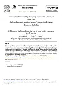
The following experiments were performed in similar fashion as the 2-D experiments. We remote-controlled the Segway to follow a near-rectangular, closed-loop path. Along the Y-axis of the trajectory, on one side of the rectangular path, we placed a double-sided ramp, which created a 3-D environment (see Figure 15a). The robot had to complete four laps going up and down the ramp before returning to the starting point. The final position errors without and with the range sensor terrain inclination algorithm are shown in Figure 15b. The slope of the ramp on both sides was about 9°, the average speed for these experiments was 200 mm/sec, and the total traveled distance 75 meters.
a
Since the ramp was placed along the Y-axis the most significant error can be expected to be in the Y-direction. Before applying IR range sensor correction: AEE ccw: Xe = 65 mm; Ye = 217 mm => 0.30% of distance traveled AEE cw: Xe = 132 mm; Ye = 285 mm => 0.42% of distance traveled After applying IR range sensor correction: AEE ccw: Xe = 82 mm; Ye = 37 mm => 0.12% of distance traveled AEE cw: Xe = 104 mm; Ye = 56 mm => 0.16% of distance traveled
5. CONCLUSIONS
b Figure 15: Experiment on 3D terrain. a. Trajectory. b. Return position errors, before and after using infrared range sensor-based terrain inclination estimation.
On rugged terrain momentary tilt information must be taken into account for correcting heading measurements, regardless of the quality of the main heading sensor (a fiber optic gyro, in our case here). To do so we developed and implemented a Fuzzy Logic expert rules-based navigation system, called FLEXnav. The Segway RMP raises a unique problem for proprioceptive position estimation: It is not possible to distinguish between the (constantly fluctuating) pitch of the robot and the actual terrain inclination. As a result, the FLEXnav proprioceptive pose estimation system (or any other Inertial Measurement Unit (IMU), for that matter), is unable to measure the terrain inclination. Consequently, odometry-based measurements of linear displacement are correct only on flat, horizontal terrain, but not if the robot traveled on a slope. To overcome this problem we developed an IR range sensor-based system that allows estimation of the relative angle between the Segway platform and the terrain. Continuous measurement of this so-called platform/terrain pitch allows our system to estimate the terrain inclination. We feel that the current IR range sensor-based system is not a very elegant solution, although it is practical and produced good experimental results. We are currently working on another approach, one that measures energy consumption based on motor current measurements, in order to estimate vertical displacement and thus, terrain pitch. This method, however, is not yet sufficiently developed to allow inclusion in this paper.
Acknowledgements This work was funded by the U.S. Department of Energy under Award No. DE-FG04-86NE3796 and by DARPA under Grant #F007571.
12
6. REFERENCES Barshan, B. and Durrant-Whyte, H.F., 1995, “Inertial Navigation Systems Mobile Robots.” IEEE Transactions on Robotics and Automation, Vol. 11, No. 3, June 1995, pp. 328-342. Biezad, D., 1999, “Integrated Navigation and Guidance Systems.” American Institute of Aeronautics and Astronautics, AIAA Education Series Borenstein, J. and Koren, Y., 1987, “Motion Control Analysis of a Mobile Robot.” Transactions of ASME, Journal of Dynamics, Measurement and Control, Vol. 109, No. 2, pp. 73-79. Borenstein, J. and Feng. L., 1996, “Measurement and Correction of Systematic Odometry Errors in Mobile Robots.” IEEE Transactions on Robotics and Automation, Vol. 12, No. 6, Dec., pp. 869-880 Jang, J.-S., Sung, C.-T. and Mizutani, E., 1997, “Neuro-Fuzzy and Soft Computing: A computational Approach to Learning and Machine Intelligence” Matlab Curriculum Series Janosi, B. Hanamoto, 1961, “Analytical Determination f Drawbar Pull as a Function of Slip for Tracked Vehicles in Deformable Soils.” Proc. of the First Int. Conf. On Terrain-Vehicle Systems, Edizioni Minerva Tecnica, Torino. Kelly, A., 1995, “An Intelligent, Predictive Control Approach to High-Speed Cross-Country Autonomous Navigation Problem.” Ph.D. Thesis. The Robotics Institute, Carnegie Mellon University, Pittsburgh, PA. Krantz, D. and Gini, M., 1996, “Non-Uniform Dead-Reckoning Position Estimate Updates.” Proc. of the 1996 IEEE Int. Conf. on Robotics and Automation Minneapolis, MN, April 22-25, pp. 2061-2066. Measurement Specialties, Inc. Fairfield, NJ 07004, http://www.msiusa.com. Ojeda, L. Chung, H., and Borenstein, J., 2000, “Precision-calibration of Fiber-optics Gyroscopes for Mobile Robot Navigation.” Proc. of the 2000 IEEE Int. Conf. on Robotics and Automation, San Francisco, CA, pp. 2064-2069. Ojeda, L. and Borenstein, J., 2002, “FLEXnav: Fuzzy Logic Expert Rule-based Position Estimation for Mobile Robots on Rugged Terrain.” Proc. of the 2002 IEEE Int. Conf. on Robotics and Automation. Washington DC, USA, 11 - 15 May, pp. 317-322. Ojeda, L. and Borenstein, J., 2004, “Methods for the Reduction of Odometry Errors in Over-constrained Mobile Robots.” Accepted for publication in Autonomous Robots. Rehbinder, H., Hu, X., 2001, “Drift-free attitude estimation for accelerometer rigid bodies.” Proc. of the 2001 IEEE Int. Conf. on Robotics and Automation, Seoul, Korea, May 21-26, 2001, pp. 4244-4249. Tonouchi, Y., Tsubouchi, T., and Arimoto, S., 1994, “Fusion of Dead-reckoning Positions with a Workspace Model for a Mobile Robot by Bayesian Inference.” Int. Conf. on Intelligent Robots and Systems (IROS '94), Munich, Germany, September 12-16, pp. 1347-1354. Companies
Analog Devices, Inc., Norwood, MA 02062, USA, http://www.analog.com. KVH Industries, Inc., 8412 W. 185th St., Tinley Park, IL 60477, USA, http://www.kvh.com. Segway LLC, 286 Commercial St., Manchester, NH 03101, USA, http://www.segway.com. Sharp Electronics Corp., 1300 Naperville Drive, Romeoville, IL 60446, USA http://sharp-usa.com.
13