Proceedings of the 2002 IEEE International Conference on Robotics and Automation. Washington DC, USA, 10 - 17 May 2002, pp. 317-322
FLEXnav: Fuzzy Logic Expert Rule-based Position Estimation for Mobile Robots on Rugged Terrain By Lauro Ojeda and Johann Borenstein* The University of Michigan, Dept. of Mechanical Engineering, Ann Arbor, Michigan, USA
[email protected] and
[email protected]* (*corresponding author) ABSTRACT Most mobile robots use a combination of absolute and relative sensing techniques for position estimation. Relative positioning techniques are generally known as deadreckoning. Many systems use odometry as their only dead-reckoning means. However, in recent years fiber optic gyroscopes have become more affordable and are being used on many platforms to supplement odometry, especially in indoor applications. Still, if the terrain is not level (i.e., rugged or rolling terrain), the tilt of the vehicle introduces errors into the conversion of gyro readings to vehicle heading. In order to overcome this problem vehicle tilt must be measured and factored into the heading computation. This paper introduces a new Fuzzy Logic Expert rulebased navigation (FLEXnav) method for fusing data from multiple low- to medium-cost gyroscopes and accelerometers in order to estimate accurately the heading and tilt of a mobile robot. Experimental results of mobile robot runs over rugged terrain are presented, showing the effectiveness of our FLEXnav method.
Coriolis gyro ($150) in conjunction with two low-cost accelerometers. A single high-quality fiber optic gyro (costing $2,000) is still used to measure the robot’s turning rate (i.e., the rotation about the platform’s z-axis). We introduce this system in Section 3. We also introduce in this paper a novel Fuzzy Logic and Expert rule-based navigation method (FLEXnav) for fusing the data from these different sensor modalities. Unlike the commonly used Kalman filter techniques for fusing sensor data [Krantz and Gini, 1996], our system is based on expert rules derived from careful observations of the physical functioning of each sensor. Our basic philosophy is that many error mechanisms can be defined more specifically and accurately by expert reasoning, based on indepth physical understanding of sensors and their associated error sources, than by the statistics-based Kalman Filter methods [Chung et al., 2001] (We do use Kalman filtering where appropriate, i.e., where noise is a dominant problem.). Our FLEXnav approach is explained in detail in Section 4. Section 5 presents experimental results, including actual robot runs over rugged terrain.
1. INTRODUCTION In recent years fiber optic gyroscopes have become very affordable, and in many mobile robots odometry and fiber optic gyroscope are combined, resulting in dramatically improved dead-reckoning accuracy [Borenstein et al., 1996]. One problem, however, is that a single gyro will not suffice to measure the change of heading of a vehicle if it turns on an incline, e.g., on rugged or rolling outdoor terrain. This is so because the sensitive axis of the vehicle-mounted gyro remains normal to the x-y plane of the vehicle, but not to the x-y plane of the world coordinate system, in which the heading angle is measured. A more detailed discussion on this issue and a definition of terms is presented in Section 2. For accurate computation of the heading of a platform it is therefore necessary to know the deviation of the platform from the horizontal plane. A good way of measuring this deviation is with a high-quality three-axis gyro system. However, while many such systems are commercially available, high-quality units typically cost over $10,000. Because this cost is inhibitive for most mobile robot applications we have developed a three-axes gyro system that measures tilt with one low-cost, two-axes
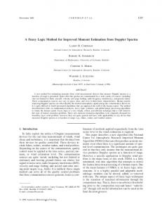
2. ATTITUDE ESTIMATION The attitude of a robot is a set of three angles measured between the robot’s body and the absolute world coordinate system. The term “navigation frame” is used for a world coordinate system, in which the x axis points east, the y axis points north, and the z axis is parallel but opposite in sign to the local gravity vector. Another coordinate system, called “body frame,” can be thought of as embedded in the robot body so that its x-axis points to the right, the y-axis points forward, and the z-axis points upward. Body axes are labeled xb, yb, and zb [Kelly et al., 1995], and the accelerometers and gyros described in this paper were mounted in alignment with these axes. Three angles express the relative orientation between the body frame and the navigation frame, as shown in Figure 1. The most common form of representation for these three angles is the so-called set of Euler angles, φ , θ , and ψ . These three angles are called roll (sometimes also called “bank angle”), pitch (also called “elevation”), and yaw (also called “heading” or “azimuth”), respectively. φ Is the angle between xb and the horizontal plane (i.e., the plane that is normal to the z-axis of the navigation frame), θ is the angle between yb and the horizontal plane, and
1
rain Eq. (3) does not hold and all three attitude parameters must be considered. 3. ATTITUDE ESTIMATION SENSORS Attitude relative to the horizontal plane xy (i.e., roll and pitch – φ and θ , respectively) is often referred to as “tilt.” Low cost tilt sensors are commercially available, typically in the form of electrolytic fluid sensors. However, most of these sensors are suitable only for static or quasi-static conditions because of their slow response time. In other words, they are suitable only for operation on very gently rolling terrain or slow speeds. For operation on rugged terrain faster tilt sensors are required. For dynamic applications requiring all three attitude parameters the conventional approach has been based on integration of rate information from sets of three mutually perpendicular gyroscopes. But such systems can be prohibitively expensive for most mobile robot applications. In this paper we described an approach that aims at using lower-cost sensing components while still providing high accuracy. We compensate for the relative poor performance of these low-cost components by taking into account the particularities of mobile robot navigation on rugged terrain, such as: 1. The mobile robot is horizontal, near horizontal or at constant tilt, most of the time. 2. Mobile robot velocities and accelerations are small – orders of magnitude lower than those of missiles or aircraft, for which most high-quality 3-axes gyro systems are designed. 3. Wheeled and even tracked vehicles allow for the use of odometry – an advantage entirely absent in aircraft or watercraft. In our system we use one accurate (but more costly) fiber optic gyro, the RA2100 made by [KVH] and two lowcost but inaccurate Coriolis gyros. In addition we used two low-cost accelerometers. In earlier work we developed a precision calibration system for this gyro that reduces the errors due to the non-linearity of the scale factor and temperature by about one order of magnitude compared to an off-the-shelf unit [Ojeda et al., 2000]. We use this rather accurate, calibrated gyro to measure the heading angle ψ, which, according to assumption (1) above, is the most important angle for land vehicles and is affected mostly by ω z (see Eq. 1). To measure the less
Figure 1: Robot axes and Euler angles (adopted from [Kelly, 1995])
ψ is the angle between x and the projection of xb on the horizontal plane [Biezad et al., 1999]. For the mathematical treatment in the following sections we define a vector Λ = [ φ , θ , ψ ]T that will represent the Euler angles throughout this paper. Rates of rotation of the body frame relative to the navigation frame can be expressed in terms of the derivatives of the Euler angles, called “Euler rates.” Specifically, Euler rates Ωε and body rates of rotation Ω b are related by:
[
Ωε = θD φD ψD
]
T
= Cbε Ω b
Where 1 sin φ tan θ ε Cb = 0 cos φ sin φ 0 cos θ
[
Ωb = ω x
ω y ωz
(1)
cos φ tan θ − sin φ cos φ cos θ
]T
ωx, ωy, and ω z are the rates of rotation of the vehicle around the respective axes of the body frame. Euler angles can be calculated from Euler rates by integrating Ωε over time:
Λ = [θ
φ ψ ]T = Ωε dt
∫
(2)
important angular rates ω x and ω y , we used a low cost
For many indoor mobile robotics applications, where floors are typically level, it is an acceptable and widely used assumption that φ and θ can be considered to equal zero. With this assumption we can rewrite Eq. (1):
ψD = ω z
two-axes Coriolis-based gyroscope made by [GYRATION]. Under assumption (1) these angular speeds will be affecting primarily φ and θ . The low-cost Coriolis gyros have significant limitations, such as large drift errors, noisy output, inaccuracy, sensitivity to acceleration, etc. We also incorporated two low-cost accelerometers made by [ANALOG DEVICES] along the xr and yr axes to estimate tilt (i.e., φ and θ ) when the robot is
(3)
According to Eq. (3) the heading angle ψ can be estimated by integrating only ω Z . However, on rugged ter-
2
static or moving linearly at constant speed (a similar sensor configuration was used in Rehbinder and Hu, 2001]). Under these conditions tilt can be calculated as follows:
Gyroscopes Gyro Roll
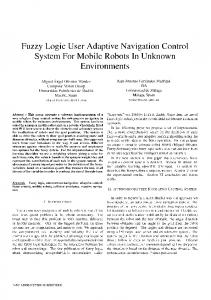
g φ = sin −1 x (4) g gy θ = sin −1 (5) g where g - gravitational acceleration gx/y - x/y-component of the gravitational acceleration Similar to gyroscopes, accelerometers suffer from bias drift problems. It is well established that accelerometers are generally not suitable for measuring linear displacement in mobile robots [Barshan and Durrant-Whyte, 1995]. This is because accelerometer measurements must be integrated twice to yield position, and thus even small amounts of drift will grow substantially and without bound. However accelerometers can be used as tilt sensors since tilt information can be derived directly from the accelerometer readings, according to Eqs. (4) and (5). No integration is needed and therefore drift is not a dominant source of errors. Rather, other error sources become relatively more significant, such as inaccuracy, noise, nonlinearity, and sensitivity to vibration. Nonetheless, accelerometers can be useful to bound and reset the tilt information calculated by the gyros when the vehicle is not moving. A block diagram of our system is shown in Figure 2, and a photograph is shown in Figure 3). Under dynamic conditions, i.e., when the robot accelerates, accelerometers will also measure the acceleration of the robot in addition to the robot’s tilt. This ambiguity can be resolved using encoder readings.
Expert system attitude estimation
Accel. X
φg ψ g
]T
Accel. Y
θ,Φ,Ψ Wheel-encoders Expert system position estimation
x,y,z
Left Front
Right Front
Left Rear
Right Rear
2001 Low-cost dead-reckoning.flo
Figure 2: Block diagram of our low-cost FLEXnav system for mobile robots.
rect for the bias drift errors of the gyroscope (see [Ojeda et al., 2000]) and reset the tilt parameters of the robot to the tilt estimated by the accelerometers (see Eqs. 4 an 5), therefore
φ ≈ φ a and θ ≈ θ a
(7)
where we define the symbol “ ≈ ” as meaning “weighted toward” instead of “equal.” Even though the sensor integration conditions are well defined and sensible, it is not feasible to implement them as strictly binary rules. This is due to the natural imprecision of the sensors and because conditions like “robot not turning” or “constant speed” are not realistic when the vehicle is in motion on rugged terrain. An integration algorithm that takes into account the physical capabilities and limitations of each sensor is therefore necessary. We found that fuzzy logic is well suited for this task. • Fuzzy logic uses rules to map inputs and outputs. Using natural language, expert rules as the ones described above can be translated easily into IF-THEN statements used by fuzzy logic rules. • Fuzzy logic is specifically designed to deal with the imprecision associated with the noisy low-cost sensors used in our system.
Based on the specific physical shortcomings and strengths of each sensor modality, we have defined the following basic expert rules: Rule 1: If the vehicle is in the process of turning about any of its axes, our best attitude estimate is the one derived from the gyroscope outputs, that is Λ ≈ Λ g , where
[
Gyro Yaw (fiber-optic)
Accelerometers
4. FUZZY DATA FUSION USING EXPERT RULES
Λg = θg
Gyro Pitch
(6)
and the index ‘g’ indicates that the value was derived from gyro data. θg, φg, and ψg are computed from gyro data according to Eqs. (1) and (2). Rule 2: If the robot is not turning around any axis and is not accelerating linearly, the accelerometers can directly measure the roll and pitch attitude parameters ( φ a and
θ a ). If the conditions of Rule 2 are met for several seconds uninterruptedly, then we can also measure and cor-
3
∆a y = a y [n ] − a y [n − 1]
(10)
∆a x ≈ 0 and ∆a y ≈ 0 means that the robot is either standing or moving with constant acceleration, and that it is standing or moving on terrain that has a constant slope. The “standing-or-moving” ambiguity is resolved using encoder information, which is the fourth input to the system. The first derivative of the velocity as measured by the encoders represents the robot’s acceleration a e = ∆v e = v e [n ] − v e [n − 1]
The outputs of the fuzzy fusion system, φτ and θτ , are dimensionless weighting factors that emphasize either the gyroscope readings, the accelerometer readings, or weigh one relative to the other. In practice these weighing factors can range from 0 to 1 and are used as follows.
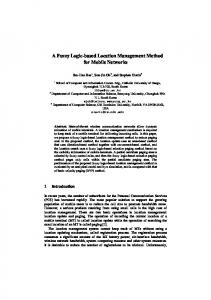
Figure 3: The components of the FLEXnav system: KVH fiber optic gyro, Gyration two-axes Coriolis gyro, and an Analog Devices two-axis accelerometer, all mounted on our Pioneer AT mobile robot.
• Trying to use a deterministic approach to solve this kind of problem would require the development of a highly non-linear system model, which, in turn, would increase the complexity and development time. Fuzzy logic, on the other hand, can handle nonlinear models of arbitrary complexity [Sang et al., 1997]. Our fuzzy data fusion uses four fuzzy membership functions1 inputs and two outputs, as shown in Figure 4. The first input represents the state of rotation (i.e., whether the platform is rotating about any axis). The parameter that determine this condition is calculated by:
ωt = ω x + ω y + ω z
φ = φ g + (φ a − φ g )φτ
(12)
θ = φ g + (θ a − θ g )θ τ
(13)
Once the inputs and outputs are identified and defined, the relationship between them must be establish. As mentioned above, fuzzy logic uses if-then rules to map inputs and outputs. For our fuzzy logic fusion system we translated our knowledge base (fusion rules) into the fuzzy rules shown in Table I. The membership functions used as input and output of our system are shown in Figure 5. It should be noted that the FLEXnav system described in this paper is only used to reduce errors in roll and pitch ( φ and θ , respectively), which would otherwise be very large because neither the accelerometers nor the low-cost gyros by themselves are very accurate. And since roll and pitch affect the computation of the heading angle ψ, as shown in Eq. (1), for rugged terrain, reducing the errors in roll and pitch reduces the errors in ψ. The experimental results in Section 5 substantiate this claim.
(8)
The second and third input use accelerometer data to determine if the acceleration of the robot is changing: ∆a x = a x [n ] − a x [n − 1]
(11)
(9)
Table I: Fuzzy logic rules used in our FLEXnav system
Figure 4: Inputs and outputs of the FLEXnav system. 1
In Fuzzy Logic, a “membership function” is defined as a curve that maps each point in the input space to a membership value or grade between 0 and 1.
ℜ1 : if ω t is not SLOW then φτ is GYRO and θτ is GYRO ℜ2 : if ∆a x is HIGH then φτ is GYRO ℜ3 : if ∆a y is HIGH then θτ is GYRO ℜ4 : if ae is HIGH then φτ is GYRO and θτ is GYRO ℜ5 : if ω t is SLOW and ∆a x is LOW and ae is LOW then φτ is ACCEL ℜ6 : if ω t is SLOW and ∆a y is LOW and ae is LOW then θτ is ACCEL ℜ7 : if ω t is SLOW and ∆a x is LOW and ae is MED then φτ is BOTH ℜ8 : if ω t is SLOW and ∆a y is LOW and ae is MED then θτ is BOTH ℜ9 : if ω t is SLOW and ∆a x is MED and ae is LOW then φτ is BOTH ℜ10 : if ω t is SLOW and ∆a y is MED and ae is LOW then θτ is BOTH ℜ11 : if ω t is MED and ∆a x is LOW and ae is LOW then φτ is BOTH ℜ12 : if ω t is MED and ∆a y is LOW and ae is LOW then θτ is BOTH ℜ13 : if ω t is MED and ∆a x is not LOW then φτ is GYRO ℜ14 : if ω t is MED and ∆a y is not LOW then θτ is GYRO ℜ15 : if ω t is MED and ae is not LOW then φτ is GYRO and θτ is GYRO
4
Figure 6: Partial view of the terrain on which the experiments were run. Moguls with up to 20° slopes were created by piles of bark surrounding the trees.
Figure 5: Membership functions of the fuzzy fusion algorithm: a), b), c) and d) are inputs; e) and f) are outputs.
5. EXPERIMENTAL RESULTS We performed several experiments to test our FLEXnav system on rugged terrain. The mobile platform used in all experiments was a Pioneer AT 4-wheel drive/skid-steer mobile robot (see Figure 3). The robot was remotely controlled to drive along a closed-loop path so that at the end of each run it returned to the initial position. The total path length was about 100 m and the durations of each trip ranged from 96-100 sec. Thus, the platform’s average speed was about 1 m/sec. During each experiment all the sensor signals where recorded for subsequent analysis. The experiments were performed on sloped and gently rolling lawn. Bark, heaped up highly around large trees on the lawn provided for somewhat steeper moguls, as shown in Figure 6. The remote operator took particular care to make the Pioneer turn right on those moguls, because we expected their slopes to introduce the largest errors. As a result, the trajectories looked irregular, as shown in Figure 7. We ran the robot several times approximately along the above described path. A set of roll and pitch angles computed only from readings from the accelerometers and Coriolis gyroscopes are shown in Figure 8a and Figure 8b for a typical run. Figure 8c show the roll and pitch angles after fusing the accelerometer and Coriolis gyro data with our FLEXnav method. Once the momentary tilt of the platform is computed (i.e., the data plotted in Figure 8c), the heading angle ψ can be computed using Eqs. (1) and (2) and the data from the high-quality fiber-optic gyroscope. Since in our experiments there was no way to measure the absolute attitude of the robot at any given time, we can compare in our experimental results only the final, computed pose (i.e., position and heading) with the actual pose of the robot. We recall that the robot was steered so that its final pose coincided with its starting pose. We performed a
Figure 7: The dashed line shows the robot’s path estimated using only the fiber optic gyro, the solid line is the estimated path of the robot according to the FLEXnav system.
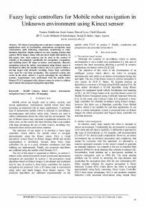
total of four runs in clockwise (cw) and four runs in counter-clockwise (ccw) direction. The resulting absolute heading errors after returning to the starting position were measured and are shown in Figure 9 for four different sensing configurations: a) with only the fiber optic gyro that measured heading (i.e., without any tilt information); and with tilt information based (b) only on the Coriolis gyros; (c) only on the accelerometers; or (d) on the FLEXnav system (Coriolis gyros and accelerometers). The results show that the FLEXnav system improves heading measurement accuracy by about one order of magnitude over the other three options. 6. CONCLUSIONS On rugged terrain momentary tilt information must be taken into account for correcting heading measurements, regardless of the quality of the main heading sensor (a fiber optic gyro, in our case here). To do so we have proposed and implemented a Fuzzy Logic Expert rules-based navigation system, called FLEXnav. The FLEXnav system compensates for the comparatively poor performance of the low-cost sensors that were used to measure tilt, thereby making them suitable for measuring tilt in a fast moving mobile robot. The tilt correction provided by our FLEXnav system results in a ten-fold improvement in heading estimation accuracy on moderately rugged ter-
5
Pitch angle θ Roll angle φ Figure 8: Roll angle (left pane) and pitch angle (right pane) of the robot as measured by a) the accelerometers, and b) the Coriolis gyroscopes. c) Roll angle φ and pitch angle θ as computed after merging accelerometer and Coriolis gyros data with our FLEXnav system.
rain, as compared to a system that uses only a single gyroscope for measuring heading or compared to systems that use only one low cost sensor modality to measure tilt (i.e., low-cost Coriolis gyros or accelerometers).
8. Krantz, D. and Gini, M., 1996, “Non-Uniform DeadReckoning Position Estimate Updates.” Proc. of the 1996 IEEE Int. Conf. on Robotics and Automation Minneapolis, MN, April 22-25, pp. 2061-2066. 9. KVH Industries, Inc., 8412 W. 185th St., Tinley Park, IL 60477, USA, http://www.kvh.com. 10. Merhav, S, 1996, “Aerospace Sensor System and Applications.” New York: Springer, 1996. 11. Ojeda, L. Chung, H., and Borenstein, J., 2000, “Precision-calibration of Fiber-optics Gyroscopes for Mobile Robot Navigation.” 2000 IEEE Int. Conf. on Robotics and Automation, San Francisco, CA, pp. 2064-2069. 12. Rehbinder, H., Hu, X., 2001, “Drift-free attitude estimation for accelerometer rigid bodies.” Proc. of the 2001 IEEE Int. Conf on Robotics and Automation, Seoul, Korea, May 21-26, 2001, pp. 4244-4249.
Acknowledgements This work was funded by DARPA under Award No. DAAE07-98-C-L029 and by DOE under Award No. DEFG04-86NE3796.
7. REFERENCES 1. Analog Devices, Inc., Norwood, MA 02062, USA, http://www.analog.com.. 2. Barshan, B. and Durrant-Whyte, H.F., 1995, “Inertial Navigation Systems Mobile Robots.” IEEE Transactions on Robotics and Automation, Vol. 11, No. 3, June 1995, pp. 328-342. 3. Borenstein, J., Everett, B., and Feng, L., 1996, “Navigating Mobile Robots: Systems and Techniques.” A. K. Peters, Ltd., Wellesley, MA, ISBN 1- ε [deg] 21.8 20.8 21.3 29.7 20.0 Fiber optic gyro only, no tilt correction 56881-058-X, Publication Date: February 1996. 19.0 Tilt correction from Corriolis gyro only 4. Chung, H., Ojeda, L. and Borenstein, J., 2001, 18.0 Tilt correction from accelerometer data only 17.0 Tilt correction from FLEXnav “Accurate Mobile Robot Dead-reckoning with a 16.0 Absolute average error for tilt correctPrecision-calibrated Fiber Optic Gyroscope.” 15.0 14.0 ion with accelerometers only (16.3 deg) IEEE Trans. on Robotics and Automation, Vol. 13.0 Absolute average error for tilt correct12.0 17, No. 1, Feb. 2001, pp. 80-84. ion with Coriolis gyros only (9.5 deg) 11.0 5. Gyration, 12930 Saratoga Avenue, Bldg. C, Sara- 10.0 9.0 toga, CA 95070, USA, http://www.gyration.com.. 8.0 Absolute average error for fiber optic 6. Jang, R, 1997, “Neuro-Fuzzy and soft computing: 7.0 gyro only, no tilt correction (9.4 deg) 6.0 a computational approach to learning and ma5.0 chine intelligence,” NJ: Prentice Hall, 1997. 4.0 Absolute average error for fiber optic gyro with FLEXnav (1.1 deg) 3.0 7. Kelly, A., 1995, “An Intelligent, Predictive Con2.0 trol Approach to High-Speed Cross-Country 1.0 0.0 Autonomous Navigation Problem.” Ph.D. Thesis. 1 2 3 4 5 6 7 8 Run # The Robotics Institute, Carnegie Mellon UniverFigure 9: Absolute return orientation errors after completing the sity, Pittsburgh, PA. 100 m run over rugged terrain.
6