Dataflow; Cloud computing; Stream processing; Cyber-physical systems; Resource ..... The Static look-ahead strategy assumes that the user (an âoracleâ) has .... and others insert/update these semantic triples to a 4Store semantic database.
Floe: A Continuous Dataflow Framework for Dynamic Cloud Applications Yogesh Simmhan and Alok Kumbhare University of Southern California Los Angeles CA 90089 {simmhan, kumbhare}@usc.edu
arXiv:1406.5977v1 [cs.DC] 23 Jun 2014
Abstract Applications in cyber-physical systems are increasingly coupled with online instruments to perform longrunning, continuous data processing. Such “always on” dataflow applications are dynamic, where they need to change the applications logic and performance at runtime, in response to external operational needs. F`oε is a continuous dataflow framework that is designed to be adaptive for dynamic applications on Cloud infrastructure. It offers advanced dataflow patterns like BSP and MapReduce for flexible and holistic composition of streams and files, and supports dynamic recomposition at runtime with minimal impact on the execution. Adaptive resource allocation strategies allow our framework to effectively use elastic Cloud resources to meet varying data rates. We illustrate the design patterns of F`oε by running an integration pipeline and a tweet clustering application from the Smart Power Grids domain on a private Eucalyptus Cloud. The responsiveness of our resource adaptation is validated through simulations for periodic, bursty and random workloads. Index Terms Dataflow; Cloud computing; Stream processing; Cyber-physical systems; Resource allocation; MapReduce
I. I NTRODUCTION Scientific and engineering applications have grown more data intensive and distributed over the past decade. Compositional models such as workflows and stream processing systems have proliferated to help design and execute complex application pipelines easily. As instruments and sensors become more pervasive – approaching the ubiquitous “Internet of Things” – these dataflow applications tend to operate over continuous data, run for extended periods, and evolve as the domain needs change. Recently, Clouds have emerged as a popular cyber-infrastructure to orchestrate and execute such dataflows. Their elastic scaling offers a unique runtime for dynamic dataflow applications. In the class of dynamic, distributed and data-intensive applications [1], the dynamism property is less well studied. Dynamism manifests both in the continuous and varying nature of data, and in the evolving application logic and performance. Consider the Smart Power Grid domain, a cyber-physical system where dataflow applications process real-time data from thousands of devices for grid operations [2]. Information integration from diverse sources and analytics on energy demand are two canonical applications here. Firstly, the integration pipeline constantly acquires data from smart meters, building sensors, and weather services, that arrive as events, XML documents and archived files, and at frequencies that vary from 1/minute to 1/day (Fig. 3(a)). As sensors expand and sampling frequencies are tuned, the performance profiles of the dataflow changes, requiring runtime adaptation to meet latency goals. The dataflow itself will also change for bug fixes and new cleaning techniques; but, the always-on nature of power grids requires in-place updates to a running dataflow’s logic. This exemplifies online application dynamism, both in the composition and in performance. Secondly, analytics help train demand forecasting models like regression tree over historical energy data using variations of the MapReduce dataflow [3]. Complex event processing [4] offers online analytics over real-time streams to detect situations like a mismatch between forecast power demand and expected supply. Graph analytics over social networks help target customers for real-time energy reduction [5]. Bulk
Synchronous Parallel (BSP) dataflows [6] are gaining traction for such graph algorithms. These diverse and specialized dataflow abstractions coexist within one domain and also need to coordinate with each other (e.g. integration → forecasting → detection → correction). These expose two key gaps in existing dataflow frameworks: (1) Missing support for application dynamism, and (2) Limited capabilities for holistic dataflow composition. Contemporary scientific workflow and stream processing systems [7], [8], [9], [10] allow eScience applications to be composed as directed task graphs, and launched for execution on computational resources such as workstations, HPC and Cloud resources. However, these frameworks do not support changes to the composition once the dataflow has been launched. Changes may include updates to the task logic or the data flow routing. Rather, the dataflow has to be stopped, recomposed, and (re)launched, or alternatively, an updated duplicate dataflow launched while the older one is quiesced. These can lead to lost data from unbuffered real-time streams, and data inconsistencies in the absence of tight coordination. There is better support for adapting to data dynamism [9] than application dynamism. But effective utilizing of Cloud elasticity to meet runtime performance metrics for continuous dataflows is still nascent. Directed cyclic or acyclic dataflow task graphs, offered by workflow and stream processing frameworks, allow a large class of applications to be composed. In practice, advanced dataflows constructs such as BSP and MapReduce are not natively supported. While MapReduce is a directed acyclic graph (DAG), the critical “shuffle” step, where mapper outputs are grouped by key and routed to specific reducers, is not efficiently handled by generic workflow frameworks, if at all. Like Hadoop for MapReduce 1 , BSP too requires special frameworks like Apache Hama 2 . Efforts to incrementally extended these frameworks with compositional semantics, such as iterative MapReduce (e.g. Twister [11]), still fail to offer rich dataflow abstractions. Else, users are forced to adopt and maintain multiple frameworks. Our own earlier work [12] addressed some issues related to flexible dataflows by integrating streams, collections and files as first-class data models (i.e. types of edges) that could be used in dataflows. This paper investigates more advanced patterns like BSP, but goes further to address issues of runtime dynamism in the application logic and adaptive resource allocations on Clouds to meet application performance needs. In summary, we make three contributions in this paper: 1) We propose design paradigms for a continuous dataflow framework to support dynamic, longrunning applications on Clouds. Besides basic dataflow patterns, the design is extensible to streaming MapReduce and BSP. Our ability to change the task logic at runtime facilitates application dynamism. (Sec. II) 2) We present the architecture of F`oε, a continuous dataflow framework for Cloud infrastructure, that supports the design paradigms for dynamic applications and uses adaptive resource allocation to meet dataflow latency goals under dynamic conditions. (Sec. III) 3) We validate our design and empirically evaluate our framework implementation on a Eucalyptus private Cloud for two real-world Smart Grid applications. In addition, our adaptive allocations are validated through simulations. (Sec. IV) II. D ESIGN PARADIGMS OF F`oε A. Flexible Dataflow Abstractions Workflow and dataflow patterns have been well examined, but scalable workflow systems, in practice, support a compact set of patterns. Here, we discuss basic and advanced patterns that go toward holistic dataflow compositional. Continuous Dataflow Model. A continuous dataflow design is foundational to F`oε, where applications are composed as a directed graph with tasks – known as pellets – as vertices and data channels connecting 1 2
Apache Hadoop, hadoop.apache.org Apache Hama, hama.apache.org
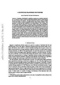
them. Pellets are user’s application logic that implement one of several compute() interfaces that are provided by the framework. Pellets expose one or more named input and output ports that can receive or emit a stream of messages. These messages may be small, serialized Java objects or large files. F`oε offers both a push and a pull model of triggering pellet execution on incoming messages. In a push interface, the framework invokes the pellet’s compute() method for each available message on the input port (Fig.1, P1). Pellet using a pull interface are designed for stream execution and their compute() method can access an iterator of messages (Fig.1, P2). Output messages can likewise be returned by the compute() interface or written to an output emitter stream. While every input message should generates one output message in a push model, pull pellets may consume zero or more messages to emit zero or more messages. For pellets with multiple ports, the inputs and outputs are a map (tuple) object whose keys are the port names and values are the corresponding message on that port (Fig.1, P5). Pellets can also receive a collection of messages that fall in a time or count window, the width of which is specified at graph composition time by the user (Fig.1, P3). Push pellets are implicitly stateless while those that pull may retain local state. F`oε provides pellets the ability to explicitly store and retrieve a state object that can be retained across pellet invocations. Using an explicit state object allows the framework to (in future) offer resilience through transparent checkpointing of the state object and resuming from the last saved state and the input messages available then. Support for large messages and a push mode of execution allows our continuous dataflow design to also be used for traditional batch processing workflows that operate on files. Basic Dataflow Abstractions. Pellets can be composed into directed graphs where ports are wired to each other to indicate dataflow between them. Control flow constructs such as if-then-else or switch can be easily implemented through pellets with multiple output ports, where the user logic emits an output message on only one of them. F`oε graphs can also have cycles, so that an output port can be connected to the input port of a “preceding” pellet. This allows iteration constructs like for-loops to be designed (Fig.1, P4). F`oε graphs support different patterns for aggregating messages from multiple pellets. A synchronous merge (Fig.1, P5) aligns messages that arrive on different input ports to create a single message tuple map, indexed by port name, that can be pulled by or pushed to the pellet. Alternatively, pellets multiple input edges can be wired to a single port as an interleaved merge (Fig.1, P6) where messages from either input edges are accessible on that input port immediately upon their arrival. Task parallelism is achieved explicitly by wiring output ports of a pellet to different pellets. When an output port of a (source) pellet is split to multiple (sink) pellets, users can decide at graph composition time an output message should be duplicated to all outgoing edges (Fig.1, P7) or sent to only one. In the latter case, a default round-robin strategy is used to select the edge as load balancing (Fig.1, P8) but a more sophisticated strategy can be employed in future (e.g. depending on the numbers of messages pending in the input queue for the sink pellet). Every pellet is inherently data parallel. The F`oε framework transparently creates multiple instances of a pellet to operate on messages available on a logical input port. The number of instances created is determined by our optimizations, discussed later. Pellet instances also share the same logical output port. One side-effect of this is that the output messages may not be in the same sequence as the input, since the pellet instances may complete out of order. Users can explicitly set an option that forces a pellet to operate sequentially without data parallelism to ensure messages flow in order. Advanced Dataflow Abstractions. The basic dataflow patterns can be composed to form complex applications and advanced constructs. For e.g., Bulk Synchronous Parallel (BSP) model has seen a revival off-late for large scale graph algorithms on Clouds [6]. BSP is an ’s’ stage (also called superstep) bi-partite dataflow where each superstep has ’m’ identical pellets that operate concurrently and emit messages to other pellets in that superstep. The message transfer itself is synchronous at superstep boundaries, and made available as input to pellets once the next superstep starts. The number of supersteps is decided at
P1: Single Execution Push
P2: Streamed Execution Pull
P3: Window Execution Push
P5: Synchronized Merge
P7: Duplicate Split
P4: Loop
P6: Interleaved Merge
P8: Round-Robin Split
M R
R
S
M R
R M
P9: Dynamic Data Mapping Map-Reduce-Reduce-… Fig. 1.
Data
M S
Control
P10: Bulk Synchronous Parallel
Subset of Dataflow Patterns supported in F`oε
runtime. We can compose a native BSP model using the basic F`oε patterns using a ’s’ fully pellets with all their output ports connected to each others’ input ports (Fig.1, P10). In addition, a manager pellet acts as a synchronization point to determine when a superstep is completed by all pellets. So “data” messages on the input port of superstep pellets are gated by a “control” message from the manager pellet on another the input port. MapReduce is another advanced dataflow pattern, constructed as a two-stage bi-partite graph from ’m’ mapper tasks to ’r’ reducer tasks. Since its “shuffle” between Mappers and Reducers does not naturally fit the basic patterns – a shortcoming of other dataflow frameworks– we introduce the notion of dynamic port mapping during a split pattern. This allows continuous MapReduce+ to be composed, with one Map stage and one or more Reduce stages (Fig.1, P9). Map and Reduce pellets are wired as a bipartite graph similar to a MapReduce dataflow, and they both emit messages as pairs. However, rather than use duplicate or round-robin split of messages from the output port of a Map pellet to the input port of the Reducer pellets, the F`oε framework performs a hash on the key to dynamically select one of the edges on which message passes, similar to Hadoop. The hash ensures that messages from any Map pellet having the same key reaches the same Reduce pellet. The Map and Reduce pellets can be used in any dataflow composition. This approach generalizes the pattern beyond just MapReduce, and allows even iterative MapReduce composition (but does away with the, often, unnecessary Map stage for the second and subsequent iterations). Also, our streaming version allows Reducers to start before all Mappers complete, and also allows operation over incremental datasets as they arrive rather than in batch mode. Pellets can emit user-defined “landmark” messages to indicate when a logical window of message streams have been processed to allow the reducer pellets to emit their result, say, when they are doing aggregation. B. Application Dynamism Continuous dataflow applications by definition run constantly, processing data streams. As a result, making updates to the application, say to fix a bug or the change the application’s behavior, can disrupt its execution; this may not be acceptable to operational dataflows. In F`oε, we explore two types of application dynamism, and mechanisms to mitigate disruption and ensure consistent results. Dynamic Task Update. A common form of application dynamism is when the logic for a single pellet needs to change during a during a dataflow execution. Stopping and starting the entire dataflow, while commonly supported, can lead to incorrect results if state is not preserved, and lead to time consuming resource reallocation. Even if we can pause a dataflow retaining the state of each pellet, it can cause data losses unless every data stream in-flight is be buffered – this can be resource intensive for high-frequency streams. We take a more nuanced approach to dynamic task updates in F`oε and allow individual pellets to be updated in-place without halting the execution of other pellets. There are several issues to consider here. An in-place task update requires that the number of ports in the old and new pellets has to be the same, as does their interfaces. Otherwise, this degenerates to dynamic dataflow update, discussed next. Internal state held by the pellet is retained if it is a stateful pellet – its state object will survive the update. Messages pending in its input ports will be retained and available to the new pellet. Depending on the degree of consistency required, task updates can be synchronous or asynchronous. If synchronous, messages being processed will finished to completion and messages already generated in its output port will be delivered before the new pellet is instantiated. The new pellet can optionally send an “update landmark” message to downstream pellets in the F`oε graph to notify them of a new logic in place. In an asynchronous update, messages being processed by pellet instances will continue to completion even while instances of the updated pellet are activated and get access to the input messages. Output messages from both the old and the new pellet instances may be interleaved.
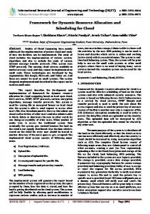
4. Instantiate 5. Wiring
Cloud Infrastructure
2. Allocate
3. Provision
Cloud Service Provider Fig. 2.
The F`oε Architecture
The advantage of this model is the zero downtime in case of asynchronous task updates, and minimal downtime for synchronous ones, limited to the time needed to finish processing input messages that have already been retrieved by a pellet instance. For pellet instances that take a long time to process a single message, the F`oε framework can optionally deliver an InterruptException to the pellet user logic to allow it to save its state and conclude processing its message. Dynamic Dataflow Update. Changes to the structure of a dataflow at runtime can have a more significant impact. One common scenario is when a sub-graph of the dataflow is added, removed or replaced. These can be reduced to the previous case of task update, where instead of one task, multiple individual pellets are added, removed or updated in-place from the dataflow in a coordinated manner. Here, synchronization goes beyond just a pellet and requires all pellets in the sub-graph to be added, removed or updated simultaneously. Here, the synchronization cost can be higher than before since the slowest pellet update becomes the bottleneck. While F`oε supports these “structural” updates, the user still needs to consider the impact on the application’s consistency in such a scenario and use the “update landmark” (or other custom mechanisms) to notify downstream pellets of the change. A more sophisticated mechanism for future, that better addresses consistency issues, is to perform a cascading update to the dataflow graph when a sub-graph is being replaced. Here, an “update tracer” message would traverse from the source pellet(s) of the sub-graph to the sink pellet(s), and perform an in-place update of each pellet when it reaches it. This form of “wave” propagation ensures that a clear distinction can be made between data streams emitted before an update and those emitted after. Pellets will still need to consider the impact of the update on stateful pellets. III. A DAPTIVE A RCHITECTURE The F`oε architecture incorporates the design patterns and dynamism we introduced, and is implemented on Cloud infrastructure. Pellets are Java classes that encapsulate the user’s application logic and implement one of several interfaces that determine the ports and the triggering mechanism. Input and output messages are Java serializable objects and may include file streams. F`oε applications are composed as a directed graph, described in XML, where vertices are pellets identified by their qualified class name and dataflow edges identify the input and output ports of the source and sink pellets they connect. Edges and
ports can be annotated with design pattern properties like data parallel execution, statefulness, window width and duplicate/round-robin split. Edges can also state if messages are transmitted synchronously from a source to a sink pellet, or is asynchronously retrieved by the sink from the source. These allow flexibility during application composition rather than deciding at pellet development time. The F`oε Cloud execution framework contains an application runtime and a resource runtime. The Coordinator and Flake are responsible for the application runtime at the F`oε graph and pellet granularities, respectively, while the Manager and Container handle resource runtime at the Cloud datacenter and Virtual Machine (VM) (Fig. 2). F`oε adopts a component model of application execution 3 so that a single centralized dataflow orchestrator is not a bottleneck. A flake is responsible for executing a single pellet in the F`oε graph and coordinating dataflow with neighboring flakes.A flake has an input and an output queue for buffering de/serialized messages to/from its pellet. Depending on the design pattern annotation, the flake aligns input messages from multiple ports or windows messages and makes it available to the pellet. Flakes also create data parallel pellet instances for consuming messages, either once for pull pellets that iterate over input messages or once per message/tuple for push pellets. Output messages from a pellet instance are placed in the output queue and the flake transmits messages to the sink pellets (flakes) directly, following the split rules, or supports asynchronous retrieval by a sink pellet (flake). F`oε offers multiple transport channels, including direct socket connections between flakes and (in future) Cloud queues, depending on performance and resilience requirements. Each flake runs on one Cloud VM, and resource provisioning within a VM is done by the container. Container manage instantiation of one or more flakes in a VM and allocates specific numbers of CPU cores to them using Java 7’s ForkJoinPool mechanism. Pellet instances created by a flake are restricted to run on the allocated core(s), allowing light-weight multi-tenancy within a VM. The ratio of the number of pellet instances to the number of cores is set to a static value (α = 4, presently). However, the numbers of cores allocated to a flake can be changed dynamically during execution time using control interfaces, giving fine-grained resource control. The coordinator parses the F`oε graph provided by the user and acquires cores on different VM containers to instantiate flakes corresponding to pellets in the graph. The coordinator negotiates with the resource manager for core allocation and the container location. The manager interacts with the Cloud service provider to acquire and release VMs on-demand based on the current need. Currently, we support the Eucalyptus Cloud fabric that is also compatible with Amazon AWS. Once flakes are active, the coordinator “wires” and activates the flakes based on the dataflow graph and design pattern annotations. The wiring is done as a bottom-up breadth-first search traversal of the dataflow (ignoring loops) to ensure that upstream pellets are not active and generating messages before downstream pellets are wired and active. The coordinator returns the input port endpoint of the initial flake(s) to the user to allow her to pass initial inputs to the dataflow, if required. Task and dataflow dynamism is handled by the coordinator, and it interacts with the flakes to pause, swap and resume the pellets. The coordinator, manager, container and flake expose REST web service endpoints for these management interactions. Resource Adaptation Strategies. The F`oε graph can be statically annotated with the number of CPU cores allocation for each pellet. The coordinator will use this information to request existing or newly instantiated containers from the manager using a best-fit algorithm. Multiple flakes may be packed in the same container, and these flakes can span multiple F`oε graphs for multi-tenancy. However, given the data dynamism, where stream rates may change over time, static core allocation can lead to over or under provisioning by the user. We investigate three resource adaptation strategies, static, dynamic, and hybrid, to handle different stream rates and periodicity, and processing latencies for pellets in the dataflow. Performance metrics we 3
Common Component Architecture, http://www.cca-forum.org
optimize for are to ensure that pellets can sustain continuous dataflow processing at the input data rate, and to bound the end-to-end processing latency for specific processing time windows. These strategies use instrumentation present within flakes for monitoring their queue lengths and average message latencies, and are used to adapt the core allocation to a flake at runtime. The Static look-ahead strategy assumes that the user (an “oracle”) has picked the best static allocation of cores for each pellet in the dataflow based on historical observations of its workload and data rates. Static allocation can be well suited when the workload is deterministic and periodic where a sample benchmark run can be extrapolated. For each of n pellets along the dataflow’s critical path, if l1..n are their per message processing latencies using one pellet instance, s1..n are the selectivity ratio of the number of output messages emitted for each input message, and m1 is the number of messages that arrive at the first pellet’s input port within a period t, then we can achieve a sustainable rate of processing along the critical path within a time tolerance of � by statically setting the number of instances of each pellet to Pi , where: Pi ' (li × mi )/(t + �) and mi = mi−1 × si . The corresponding number of cores, using a static instance to core ratio of α = 4, is Ci = dPi /4e. The dynamic strategy uses continuous monitoring of the pellet to adapt the number of its instances. It is better suited for workloads where the data rates are slow changing but not predictable a priori. The goal of this strategy is to ensure that the instantaneous rate at which input messages are arriving at a pellet can be matched by the rate at which output messages are being emitted by that pellet’s instances, after accounting for the selectivity ratio. The dynamic algorithm is triggered at regular intervals at which time it evaluates the rate of incoming data as well as the processing rate based on the task latency and the number of currently running pellet instances. If the data rate is observed to be greater than the data processing latency by a threshold, it increases the number of cores assigned to the pellet (and in turn the number of parallel instances by a factor of α). On the other hand, if the data rate is less than the data processing latency by a threshold, it further checks if decreasing the number of allocated cores would violate this condition, if not, it decreases the number of allocated cores. The second check is necessary to ensure that the number of allocated cores do not fluctuate too often. The static look-ahead strategy is well suited for periodic dataflows while the dynamic adaptation gradually evolves with changing rates. However, dataflows rarely fall under either extremes. We introduce a hybrid strategy that takes hints on data rate and periodicity, like the static strategy, but does not assume that the user is an “oracle”. Rather, it adapts and switches to a dynamic strategy when the expected data rates start to veer off beyond a threshold. It switches back to the static strategy when the data rate stabilizes close to the hinted average value and the number of pending messages in the queue is below a threshold. Data: DataRate D, ProcessingLatency L, # pellet instances N ; δ=D− N L if δ ≥ τ1 then increment allocated cores by 1; else if δ ≤ τ2 and δ < − NL−1 then decrement allocated cores by 1; end end
Algorithm 1: Dynamic Adaptation of Cores for Flake Dynamic adaptation requires continuous monitoring, and its effectiveness depends on the sampling frequency (with its associated overheads). Further, the dynamic approach can only increase the core allocation for a flake within a single VM (cross-VM elasticity and migration of flakes is planned for future) while the static look-ahead can help split resource intensive pellets across multiple flakes at design time. However, as our evaluation in Section IV shows that dynamic adaptation is more robust to dataflows with variability. The hybrid adaptation attempts to get the best of both worlds. Our current
I4
I7
Query & Insert
Recurrent Transport
I6
I0
Sensor Extract 1 → 20 0.01s
I1
I2 Push Transport
Parser
1 → 250 0.5s
1 → 10 0.5s
Sensor Pull 10 → 1 1s
Cluster Search
10 → 1 1.5s
TBD
I3
Semantic Switch
I7
1→1 0.1s
I8
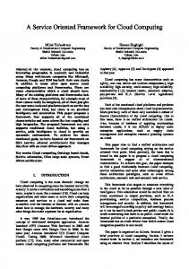
(a) Information Integration Pipeline
Bucketize
I5 Insert Where
Progress Meter
10 → 1 1.5s
1→1 0.5s
Sensor Extract TBD
Cluster Search
Text Cleaning Bucketize
T0
Cluster Search
Aggregator
T6
T1,2
(b) Online Stream Clustering
T3,4,5
Fig. 3. Smart Power Grid applications using F`oε. Pellets in the pipeline show selectivity ratio from input → output, and message processing time.
F`oε implementation supports the static strategy if provided by the user and defaults to the dynamic strategy; implementing hybrid is part of future work. IV. C ASE S TUDY A PPLICATIONS AND E VALUATION We present an illustrative evaluating of F`oε’s patterns in two representative real-world applications from Smart Power Grids, along empirical observations of their execution on a Eucalyptus private Cloud. Further, we also validate our resource adaptation stategies through simulation, for three different data stream workloads. A. Smart Grid Information Integration Pipeline A Smart Grid information pipeline integrates diverse data from the cyber-physical system into a knowledge database for analysis and grid operations. The pipeline used at the USC Campus Microgrid (Fig. 3(a)), a testbed for the Los Angeles Smart Grid project, is composed of pellets that periodically stream events from campus meters and sensors (I0 , I1 ), have historical CSV meter data uploaded in bulk occasionally (I6 ), and XML documents fetched from NOAA weather services (I7 ). Data from these sources are parsed by a pellet to extract information (I7 ), another pellet semantically annotates the event tuples to provide context (I3 ), and others insert/update these semantic triples to a 4Store semantic database (I4 , I8 , I9 ). The ingest progress is available by an output pellet (I5 ). This pipeline exhibits many of the F`oε design patterns, including streamed execution pull (I1 ), interleaved merge (I2 ), switch control flow (I3 ), and single execution push (T5 ). Many pellets use single messages but some use map tuples (I3 ). Task parallelism is apparent, and some (I2 , I4 ) allow multiple pellet instances for data parallel execution. This F`oε graph, in active use on USC campus, runs on the Tsangpo private Eucalyptus Cloud having 128 cores in 16 nodes. The graph uses containers on 7 Extra Large VM instances (8 cores and 16 GB RAM each), and by default, one flake is assigned to one container with dynamic adaptation strategy. Two additional VMs host the F`oε coordinator and manager. B. Distributed Online Stream Clustering Stream clustering is an important precursor for many real-time microblog post and tweet analytics algorithms. In Smart Grids, it can help utilities understand energy efficiency trends, and help recommend appropriate customers for demand reduction. Stream clustering distributes posts from incoming microblog feeds, which have a mix of topics, into output topic streams that groups posts with a high likelihood of being in a topic. A distributed version of Locality Sensitive Hashing (LSH) [13] algorithm for stream clustering can be composed as a F`oε graph. LSH is a family of hash functions H = {h : S → U } such that ∀p, q : p ∈ B(q, r1) ⇒ P rH [h(q) = h(p)] ≥ p1 and ∀p, q : p ∈ / B(q, r2) ⇒ P rH [h(q) = h(p)] ≤ p2, for some p1, p2, r1, r2. In other words, if two points are close together, then they remain close after a
12 8
100 50
8 4
50 0
4 0 25
0
25
50
75
100
Simulation Time (secs) 50
75
for Pellet for Pellet # of Cores # of Cores
8 7 8 6 7 5 6 4 5 3 4 2 3 1 2 0 1 0 0 0
0
100
Simulation Time (secs)
125 125
static hybrid
25
50
75
100
125
50
75
100
125
Simulation Time (secs) Simulation Time (secs)
hybrid dynamic data rate static
250 300
hybrid data rate
200 250 150 200 100 150 50 100
0 50 50 0 25 50 75 100 125 150 175 200 225 250 275 300 325 350 375 400 Simulation Time (secs) 0 0 0 25 50 75 100 125 150 175 200 225 250 275 300 325 350 375 400
7,000 6,000 7,000 5,000 6,000 4,000 5,000 3,000 4,000 2,000 3,000 1,000 2,000 0 1,000
35
Random Data Rate
0
100
200
300
400
500
0
100
200
300
400
500
0
30 35 25 30 20 25 15 dynamic 20 static 10 hybrid 15 dynamic data rate 5 static 10 hybrid 0 data rate 5 600 700 800 900 1000 1100 1200 1300 1400 1500 1600 Simulation Time (secs) 0 600 700 800 900 1000 1100 1200 1300 1400 1500 1600
Simulation Time (secs)
Simulation Time (secs) (a) Message 8Count in Input Queue (Y1) & Incoming Data Rate (Y2) for Pellet I1 over Time dynamic dynamic static hybrid dynamic
25
300
8
static 7 8 hybrid dynamic 6 static 7 5 hybrid 6 4 5 3 4 2 3 1 2 0 1 0 25 50 75 100 125 150 175 200 225 250 275 300 325 350 375 400 0 Simulation Time (secs) 0 25 50 75 100 125 150 175 200 225 250 275 300 325 350 375 400
for Pellet for Pellet # of Cores # of Cores
0 0
Random Data Rate
dynamic
Periodic Data Rate with static Spikes
Rate (1/sec) Rate (1/sec) Message Message Input Input
16 12
150 100
600 550 500 600 450 550 400 500 350 450 300 400 250 350 200 300 150 250 100 200 50 150 0 100
CountCount QueueQueue Pellet Pellet
20 16
CountCount QueueQueue Pellet Pellet
200 150
20
Rate (1/sec) Rate (1/sec) Message Message Input Input
250 200
Periodic Data Rate with Spikes dynamic static hybrid dynamic data rate static hybrid data rate
for Pellet for Pellet # of Cores # of Cores
CountCount QueueQueue Pellet Pellet
Periodic Data Rate
Rate (1/sec) Rate (1/sec) Message Message Input Input
Periodic Data Rate 250
7 8 6 7 5 6 4 5 3 4 2 3 1 2 0 1 0 0 0
100
200
300
400
500
600
100
200
300
400
500
600
700
800
900
dynamic static hybrid dynamic static hybrid 1000 1100 1200 1300 1400 1500 1600
Simulation Time (secs)
Simulation Time (secs)
700
800
900
1000 1100 1200 1300 1400 1500 1600
Simulation Time (secs)
(b) Number of Core Allocations for Pellet I1 over Time Fig. 4.
Simulation plots show resource behavior of pellet I1 for periodic, periodic w/ spikes and random data rates.
projection operation using a LSH, and these hash functions can significantly reduce the nearest neighbor search space. Fig. 3(b) shows the F`oε graph for stream clustering operating on streams from various news feeds. Text Cleaning pellet (T0 ) cleans the posts using stemming, stop-word removal, and spell-check to generate a feature vector based on dictionary of topic words. The Bucketizer (T1 , T2 ) applies LSH to the vector to generate a several hash values that indicate stream buckets with a high similarity to the post. We use F`oε’s dynamic data mapping pattern, that is similar to but more versatile than MapReduce, to continuously route and automatically group posts to specific Cluster Search pellets (T3 , T4 , T5 ). Data parallel pellet instances of Cluster Search find the closest locally matching cluster among the candidate buckets, acting as a local “combiner” on the reducer’s output. These locally closest results are sent to the Aggregator pellet (T6 ) to find the global best cluster for the post. A further feedback loop (with choice) notifies one of the Cluster Search pellets of the updated post in its bucket, to be include in future comparisons. The dynamic data mapping and loop offered by F`oε for continuous processing makes this an elegant and efficient solution for low-latency online analytics. C. Validation of Dynamic Allocation Strategies The F`oε framework currently supports static and dynamic adaptation, but not hybrid. To perform a uniform comparison, simulate the Information Integration Pipeline (Fig.3(a)) and compare the resource adaptation strategies under different load profiles of input messages entering the dataflow at I0 . We focus on three profiles observed in our applications: periodic with a constant data rate, random data rate with fluctuations similar to a one dimensional random walk, and periodic with spikes at random in the data rate. The I1 pellet is used representatively in the discussions, and we use a period of 5 mins and data duration of 60 secs for the periodic data rates (i.e. 1 min data stream, 4 mins of gap). Fig. 4(b)(left) shows the number of allocated cores for over simulation time as it is changed by the different strategies based on the periodic data rate. The static look-ahead strategy allows a user-defined tolerance latency (�=20 secs) to complete data processing in a period, on top of the data duration, and allocates the minimum number of cores to meet this latency goal. Fig. 4(a)(left) shows this threshold of 80 secs being met at 75 secs, when the pellet’s input queue has been drained. The dynamic strategy gradually allocates enough cores to achieve a steady state processing (output data rate = input data rate) and hence finishes earlier at 70 secs, but at the cost of some extra resources in that duration as seen by the area under the curve in Fig. 4(b)(left). For the periodic workload profile, the hybrid strategy performs
similar to the static look-ahead strategy, but additionally quiesces to 0 cores once done processing, like the dynamic strategy. For periodic with random spikes in the data rate, the static look-ahead strategy misses the specified latency tolerance since it optimizes for the expected periodic data and is unable to handle the unexpected data surges (Fig. 4(a)(center)). The dynamic strategy is able to process all messages within the given tolerance while having a larger peak in core allocation (Fig. 4(b)(center)). However, this is justified by its handling the data burst and gracefully draining its input queue, as seen by the flat message count level. The hybrid model performs better than the static model and finishes processing the messages within the given tolerance while using less resources than the dynamic model. The last load profile has a random data rate with a known long-term average rate and slow variation. (Fig. 4(a)(right)). We observe that the static look-ahead strategy that optimizes for only for the expected average data rate performs poorly and its input queue length (and hence the queuing latency) accumulates over time. In contrast, the dynamic and hybrid strategy adapt the number of cores dynamically to the data rate and are able to keep the pending input messages negligible. In addition, the ratio of cumulative resources (area under the curves in Fig.4(b)(right)) used by the static, the dynamic and the hybrid strategies is 0.87 : 1.00 : 0.98. This indicates that while the static look-ahead uses almost the same resources as the other two, it performs much worse. Hence, we can surmise that the hybrid approach gives the broadest measure of good results, in terms of limiting violation of the latency, while conserving the resources used by the pellets, under different load profiles. V. R ELATED W ORK Scientific workflow systems such as Kepler/ COMAD [8] and Pegasus [7] have explored different facets of distributed and data intensive processing of control and data flow applications. Most of these systems have been developed for one-shot batch processing workflows processing using files or objects while some such as Kepler/COMAD also support operations over collections. There has also been some work on incorporating stream processing into these workflow systems such as Kepler [14] and Confluence [15], however these systems lack support for rich programming abstractions for stream based execution, especially support for dynamic key mapping (MapReduce) and BSP models that are supported by F`oε. Systems such as granules [16], on the other hand, focus on particular abstractions such as MapReduce but fail to provide a generic stream processing model that can integrate various dataflow patterns with advanced patterns such as MapReduce. S4[9] and IBM Stream processing core (SPC)[10] provide a very similar distributed stream processing environment as F`oε. It also provides generic programming model where the use can define the processing elements, similar to F`oε’s pellets, that can be composed to form a continuous dataflow application. However, unlike F`oε, these system lack elastic scaling based on the dynamic data rate. There is yet another body of work on stream processing for continuous data streams and events, dating back to work on the TelegraphCQ[17] and Aurora [18]. More recently, Schneider et. al. [19] developed a system built on top of the SPADE system to allow Operator Elasticity, wherein the standard operators perform their computations in parallel, while also dynamically adapting parallelism level to obtain the best performance based on the current system load. These optimizations are similar to the dynamic resource allocation strategy in F`oε, however, in addition we exploit the estimated data characteristics though the static look-ahead and hybrid strategies that minimizes resource utilization while conforming to the latency requirements. StreamCloud[20] is another stream processing system that focuses on scalability with respect to the stream data rates. StreamCloud achieves this by partitioning the incoming data stream with semantic awareness about the operator in the downstream instance and achieves scalability with intra-operator parallelism and dynamic resource allocation. Esc [21] is a novel elastic stream processing platform that
offers a streaming model using Cloud resources on-demand to adapt to changing computational demands. Esc allows the end user to specify adaptation strategies in terms of data partitioning as well splitting individual tasks into smaller parallel tasks based on the workload. The optimizations in F`oε do not assume any pellet semantics and the optimizations are performed implicitly by the framework by exploiting the data parallel nature of the operations or explicitly by the application composer by using the data based choice or round robin split patterns for load balancing. Application dynamism have be explored using concepts such as frames, templates and dynamic embedding[22]. However, these are in the context of scientific workflows where the choice for the dynamic task is finalized before the execution of that task begins which is in contrast to the requirement in the continuous dataflows where an executing task needs to be seamlessly updated at runtime as is support by F`oε. VI. C ONCLUSIONS In this article, we have motivated the needs of an emerging class of dynamic, continuous dataflow applications, that are unique in the application and dynamism they exhibit, and the rich composition patterns they use. Our work has explored the design paradigms for a Cloud-based framework, F`oε, to meet these needs, with elastic optimizations to meet variable streaming data rates. Our future work will pursue research novel problems related to resiliency of these applications, and additional optimizations evaluated under real Cloud environments. R EFERENCES [1] D. S. Katz, S. Jha, N. C. Hong, S. Dobson, A. Luckow, O. Rana, and Y. Simmhan, “3dpas review for d3science,” in D3Science Workshop, 2011. [2] Y. Simmhan, V. Prasanna, S. Aman, S. Natarajan, W. Yin, and Q. Zhou, “Towards data-driven demand-response optimization in a campus microgrid,” in Workshop On Embedded Sensing Systems For Energy-Efficiency In Buildings (BuildSys). ACM, 2011, demo. [3] W. Yin, Y. Simmhan, and V. Prasanna, “Scalable regression tree learning on hadoop using openplanet,” in MAPREDUCE, 2012. [4] Q. Zhou, Y. Simmhan, and V. K. Prasanna, “Semantic complex event processing for smart grid information integration and management,” in Energy Forum: A System Approach Toward Green Energy Production and Adaptive Power Distribution. IEEE Coastal Los Angeles Section, 2010, poster. [5] P. Petkov, F. K¨obler, M. Foth, and H. Krcmar, “Motivating domestic energy conservation through comparative, community-based feedback in mobile and social media,” in Proceedings of the 5th International Conference on Communities and Technologies. ACM, 2011. [6] G. Malewicz, M. Austern, A. Bik, J. Dehnert, I. Horn, N. Leiser, and G. Czajkowski, “Pregel: a system for large-scale graph processing,” in Proceedings of the 2010 international conference on Management of data. ACM, 2010, pp. 135–146. [7] E. Deelman, J. Blythe, Y. Gil, and C. Kesselman, “Pegasus: Planning for Execution in Grids,” 2002. [8] B. Ludscher, I. Altintas, C. Berkley, D. Higgins, E. Jaeger, M. Jones, E. Lee, J. Tao, and Y. Zhao, “Scientific Workflow Management and the Kepler System,” Concurrency and Computation: Practice and Experience, 2005. [9] L. Neumeyer, B. Robbins, A. Nair, and A. Kesari, “S4: Distributed stream computing platform,” in Data Mining Workshops (ICDMW), 2010 IEEE International Conference on. IEEE, 2010, pp. 170–177. [10] L. Amini, H. Andrade, R. Bhagwan, F. Eskesen, R. King, P. Selo, Y. Park, and C. Venkatramani, “Spc: A distributed, scalable platform for data mining,” in Proceedings of the 4th international workshop on Data mining standards, services and platforms. ACM, 2006, pp. 27–37. [11] J. Ekanayake, H. Li, B. Zhang, T. Gunarathne, S.-H. Bae, J. Qiu, and G. Fox, “Twister: A runtime for iterative mapreduce,” in Workshop on MapReduce and its Applications (MAPREDUCE), 2010. [12] D. Zinn, Q. Hart, T. M. McPhillips, B. Ludscher, Y. Simmhan, M. Giakkoupis, and V. K. Prasanna, “Towards reliable, performant workflows for streaming-applications on cloud platforms,” in International Symposium on Cluster, Cloud and Grid Computing (CCGRID). IEEE, 2011. [13] A. Gionis, P. Indyk, R. Motwani et al., “Similarity search in high dimensions via hashing,” in Proceedings of the International Conference on Very Large Data Bases, 1999, pp. 518–529. [14] D. Zinn, Q. Hart, T. M. McPhillips, B. Ludscher, Y. Simmhan, M. Giakkoupis, and V. K. Prasanna, “Towards reliable, performant workflows for streaming-applications on cloud platforms,” in International Symposium on Cluster, Cloud and Grid Computing (CCGRID). IEEE, 2011, pp. 235–244. [15] P. Neophytou, P. Chrysanthis, and A. Labrinidis, “Confluence: Implementation and application design,” in Collaborative Computing: Networking, Applications and Worksharing (CollaborateCom), 2011 7th International Conference on, oct. 2011, pp. 181 –190. [16] S. Pallickara, J. Ekanayake, and G. Fox, “Granules: A lightweight, streaming runtime for cloud computing with support, for map-reduce,” in Cluster Computing and Workshops, 2009. CLUSTER’09. IEEE International Conference on. IEEE, 2009, pp. 1–10.
[17] S. Chandrasekaran, O. Cooper, A. Deshpande, M. Franklin, J. Hellerstein, W. Hong, S. Krishnamurthy, S. Madden, F. Reiss, and M. Shah, “Telegraphcq: continuous dataflow processing,” in Proceedings of the 2003 ACM SIGMOD international conference on Management of data. ACM, 2003, pp. 668–668. [18] D. J. Abadi, D. Carney, U. C ¸ etintemel, M. Cherniack, C. Convey, S. Lee, M. Stonebraker, N. Tatbul, and S. Zdonik, “Aurora: a new model and architecture for data stream management,” The VLDB Journal, vol. 12, pp. 120–139, August 2003. [19] S. Schneider, H. Andrade, B. Gedik, A. Biem, and K.-L. Wu, “Elastic scaling of data parallel operators in stream processing,” in Parallel Distributed Processing, 2009. IPDPS 2009. IEEE International Symposium on, may 2009, pp. 1 –12. [20] V. Gulisano, R. Jimenez-Peris, M. Patino-Martinez, and P. Valduriez, “Streamcloud: A large scale data streaming system,” in Distributed Computing Systems (ICDCS), 2010 IEEE 30th International Conference on, june 2010, pp. 126 –137. [21] B. Satzger, W. Hummer, P. Leitner, and S. Dustdar, “Esc: Towards an elastic stream computing platform for the cloud,” in Cloud Computing (CLOUD), 2011 IEEE International Conference on, july 2011, pp. 348 –355. [22] A. H. H. Ngu, S. Bowers, N. Haasch, T. M. Mcphillips, and T. Critchlow, Flexible Scientific Workflow Modeling Using Frames, Templates, and Dynamic Embedding, 2008.