Report 4: Flow Charts and Data Models for Initial Commissioning of Advanced and Low Energy Building Systems
Flow Charts and Data Models for Initial Commissioning of Advanced and Low Energy Building Systems A Report of Cost-Effective Commissioning of Existing and Low Energy Buildings Annex 47 of the International Energy Agency Energy Conservation in Buildings and Community Systems Program REPORT EDITORS Ömer Akın (Carnegie Mellon University) Natascha Milesi Ferretti (National Institute of Standards and Technology) Daniel Choiniere (Natural Resources Canada) David Claridge (Texas A&M University) AUTHORED BY Ömer Akın (Carnegie Mellon University), Natasa Djuric (Norwegian University of Science and Technology), Karel Kabele (Czech Technical University), Michal Kabrhel (Czech Technical University), Kwang Jun Lee, Christian Neuman (Fraunhofer Institute for Solar Energy Systems ISE), Alexis Versele (KaHo St-Lieven), Shengwei Wang (Hong Kong Polytechnic University), Harunori Yoshida (Kyoto University) ANNEX 47 OPERATING AGENTS Natascha Milesi Ferretti (National Institute of Standards and Technology) Daniel Choiniere (Natural Resources Canada)
November 2010
CITATION Flow Charts and Data Models for Initial Commissioning of Advanced and Low Energy Building Systems. A Report of Cost-Effective Commissioning of Existing and Low Energy Buildings. Energy Conservation in Buildings and Community Systems Program. Copies of this report may be obtained from the Annex 47 web site at: http://www.iea-annex47.org or from the IEA/ECBCS Bookshop at: www.ecbcs.org. DISCLAIMER This report is distributed for information purposes only and does not necessarily reflect the views of the Operating Agents (Government of the United States of America through the National Institute of Standards and Technology and Government of Canada through the Department of Natural Resources Canada) nor does it constitute an endorsement of any commercial product or person. All property rights, including copyright, are vested in the Operating Agent on behalf of the International Energy Agency Energy Conservation in Buildings and Community Systems Program (IEA/ECBCS) for the benefits of the Annex 47 Participants, provided, however, that the Participants may reproduce and distribute such material, but if it shall be published with a view to profit, permission should be obtained from the IEA/ECBCS. In particular, no part of this publication may be reproduced, stored in a retrieval system or transmitted in any form or by any means, electronic, mechanical, photocopying, recording or otherwise, without the prior written permission of the Operating Agent. Participating countries in ECBCS: Australia, Austria, Belgium, Canada, P.R. China, Czech Republic, Denmark, Finland, France, Germany, Greece, Italy, Japan, Republic of Korea, the Netherlands, New Zealand, Norway, Poland, Portugal, Spain, Sweden, Switzerland, Turkey, United Kingdom and the United States of America.
Preface International Energy Agency The International Energy Agency (IEA) was established in 1974 within the framework of the Organisation for Economic Co-operation and Development (OECD) to implement an international energy programme. A basic aim of the IEA is to foster co-operation among the twenty-eight IEA participating countries and to increase energy security through energy conservation, development of alternative energy sources and energy research, development and demonstration (RD&D). Energy Conservation in Buildings and Community Systems The IEA co-ordinates research and development in a number of areas related to energy. The mission of one of those areas, the ECBCS - Energy Conservation for Building and Community Systems Programme, is to develop and facilitate the integration of technologies and processes for energy efficiency and conservation into healthy, low emission, and sustainable buildings and communities, through innovation and research. The research and development strategies of the ECBCS Programme are derived from research drivers, national programmes within IEA countries, and the IEA Future Building Forum Think Tank Workshop, held in March 2007. The R&D strategies represent a collective input of the Executive Committee members to exploit technological opportunities to save energy in the buildings sector, and to remove technical obstacles to market penetration of new energy conservation technologies. The R&D strategies apply to residential, commercial, office buildings and community systems, and will impact the building industry in three focus areas of R&D activities: Dissemination Decision-making Building products and systems The Executive Committee Overall control of the program is maintained by an Executive Committee, which not only monitors existing projects but also identifies new areas where collaborative effort may be beneficial. To date the following projects have been initiated by the executive committee on Energy Conservation in Buildings and Community Systems (completed projects are identified by (*)): Annex 1: Load Energy Determination of Buildings (*) Annex 2: Ekistics and Advanced Community Energy Systems (*) Annex 3: Energy Conservation in Residential Buildings (*) Annex 4: Glasgow Commercial Building Monitoring (*) Annex 5: Air Infiltration and Ventilation Centre Annex 6: Energy Systems and Design of Communities (*) Annex 7: Local Government Energy Planning (*) Annex 8: Inhabitants Behaviour with Regard to Ventilation (*) Annex 9: Minimum Ventilation Rates (*) Annex 10: Building HVAC System Simulation (*) Annex 11: Energy Auditing (*) Annex 12: Windows and Fenestration (*) Annex 13: Energy Management in Hospitals (*) Annex 14: Condensation and Energy (*) Annex 15: Energy Efficiency in Schools (*) Annex 16: BEMS 1- User Interfaces and System Integration (*)
2
Annex 17: BEMS 2- Evaluation and Emulation Techniques (*) Annex 18: Demand Controlled Ventilation Systems (*) Annex 19: Low Slope Roof Systems (*) Annex 20: Air Flow Patterns within Buildings (*) Annex 21: Thermal Modelling (*) Annex 22: Energy Efficient Communities (*) Annex 23: Multi Zone Air Flow Modelling (COMIS) (*) Annex 24: Heat, Air and Moisture Transfer in Envelopes (*) Annex 25: Real time HVAC Simulation (*) Annex 26: Energy Efficient Ventilation of Large Enclosures (*) Annex 27: Evaluation and Demonstration of Domestic Ventilation Systems (*) Annex 28: Low Energy Cooling Systems (*) Annex 29: Daylight in Buildings (*) Annex 30: Bringing Simulation to Application (*) Annex 31: Energy-Related Environmental Impact of Buildings (*) Annex 32: Integral Building Envelope Performance Assessment (*) Annex 33: Advanced Local Energy Planning (*) Annex 34: Computer-Aided Evaluation of HVAC System Performance (*) Annex 35: Design of Energy Efficient Hybrid Ventilation (HYBVENT) (*) Annex 36: Retrofitting of Educational Buildings (*) Annex 37: Low Exergy Systems for Heating and Cooling of Buildings (LowEx) (*) Annex 38: Solar Sustainable Housing (*) Annex 39: High Performance Insulation Systems (*) Annex 40: Building Commissioning to Improve Energy Performance (*) Annex 41:Whole Building Heat, Air and Moisture Response (MOIST-ENG) (*) Annex 42: The Simulation of Building-Integrated Fuel Cell and Other Cogeneration Systems (FC+COGEN-SIM) (*) Annex 43:Testing and Validation of Building Energy Simulation Tools (*) Annex 44:Integrating Environmentally Responsive Elements in Buildings Annex 45:Energy Efficient Electric Lighting for Buildings (*) Annex 46: Holistic Assessment Tool-kit on Energy Efficient Retrofit Measures for Government Buildings (EnERGo) Annex 47:Cost-Effective Commissioning for Existing and Low Energy Buildings Annex 48:Heat Pumping and Reversible Air Conditioning Annex 49:Low Exergy Systems for High Performance Buildings and Communities Annex 50:Prefabricated Systems for Low Energy Renovation of Residential Buildings Annex 51:Energy Efficient Communities Annex 52:Towards Net Zero Energy Solar Buildings Annex 53:Total Energy Use in Buildings: Analysis & Evaluation Methods Annex 54:Analysis of Micro-Generation & Related Energy Technologies in Buildings Annex 55:Reliability of Energy Efficient Building Retrofitting - Probability Assessment of Performance & Cost (RAP-RETRO) Annex 56:Energy and Greenhouse Gas Optimised Building Renovation Working Group - Energy Efficiency in Educational Buildings (*) Working Group - Indicators of Energy Efficiency in Cold Climate Buildings (*) Working Group - Annex 36 Extension: The Energy Concept Adviser (*) Working Group - Energy Efficient Communities (*) – Completed Annex 47
3
The objectives of Annex 47 were to enable the effective commissioning of existing and future buildings in order to improve their operating performance. The main objective of this Annex was to advance the state-of-the-art of building commissioning by: Extending previously developed methods and tools to address advanced systems and low energy buildings, utilizing design data and the buildings’ own systems in commissioning Automating the commissioning process to the extent practicable Developing methodologies and tools to improve operation of buildings in use, including identifying the best energy saving opportunities in HVAC system renovations Quantifying and improving the costs and benefits of commissioning, including the persistence of benefits and the role of automated tools in improving persistence and reducing costs without sacrificing other important commissioning considerations To accomplish these objectives Annex 47 has conducted research and development in the framework of the following three Subtasks: Subtask A: Initial Commissioning of Advanced and Low Energy Building Systems This Subtask addressed what can be done for (the design of) future buildings to enable cost-effective commissioning. The focus was set on the concept, design, construction, acceptance, and early operation phase of buildings. Subtask B: Commissioning and Optimization of Existing Buildings This Subtask addressed needs for existing buildings and systems to conduct cost-effective commissioning. The focus here was set on existing buildings where the conditions for commissioning need to be afforded without documentation and limited means for integrated commissioning. Subtask C: Commissioning Cost-Benefits and Persistence This Subtask addressed how the cost-benefit situation can be represented. Key answers were provided by developing international consensus methods for evaluating commissioning cost-benefit and persistence. The methods were implemented in a cost-benefit and persistence database using field data.
4
Annex 47 was an international joint effort conducted by 50 organizations in 11 countries: KaHo St-Lieven, Ghent University, PHP Passive house platform, Université de Liège, Katholieke Universiteit Leuven Natural Resources Canada (CETC-Varennes), Public Works and Governmental Services Canada, Palais de Congres de Montreal, Hydro Quebec, Profac Czech Technical University
Belgium
Canada
Czech Republic
Finland
Germany
Hong Kong/China
VTT Technical Research Centre of Finland, Helsinki University of Technology Ebert-Baumann Engineers, Institute of Building Services and Energy Design, Fraunhofer Institute for Solar Energy Systems ISE Hong Kong Polytechnic University
Hungary
University of Pécs
Japan
Netherlands
Norway
USA
Kyoto University, Kyushu University, Chubu University, Okayama University of Science, NTT Facilities, Osaka Gas Co., Kansai Electric Power Co., Kyushu Electric Power Co., SANKO Air Conditioning Co, Daikin Air-conditioning and Environmental Lab, Tokyo Electric Power Co, Tokyo Gas Co., Takenaka Corp, Chubu Electric Power Co., Tokyo Gas Co., Ltd., Tonets Corp, Nikken Sekkei Ltd, Hitachi Plant Technologies, Mori Building Co., Takasago Thermal Engineering Co., Ltd. Institute for Building Environment and Energy Conservation TNO Environment and Geosciences, University of Delft Norwegian University of Science and Technology, SINTEF National Institute of Standards and Technology, Texas A&M University, Portland Energy Conservation Inc., Carnegie Mellon University, Johnson Controls, Siemens,
5
Lawrence Berkeley National Laboratory
6
FOREWORD This report summarizes part of the work of IEA-ECBCS Annex 47 Cost-Effective Commissioning of Existing and Low Energy Buildings. It is based on the research findings from the participating countries. The publication is an official Annex report. Report 1 can be considered as an introduction to the commissioning process. Report 2 provides general information on the use of tools to enhance the commissioning of low energy and existing buildings, summarizes the specifications for tools developed in the Annex and presents building case studies. Report 3 presents a collection of data that would be of use in promoting commissioning of new and existing buildings and defines methods for determining costs, benefits, and persistence of commissioning, The report also highlights national differences in the definition of commissioning. Report 4 provides a state of the art description of the use of flow charts and data models in the practice and research of initial commissioning of advanced and low energy building systems. Abbreviations are presented before the Executive Summary to facilitate the understanding of the terms used. In many countries, commissioning is still an emerging activity and in all countries, advances are needed for greater formalization and standardization. We hope that this report will be useful to promote best practices, to advance its development and to serve as the basis of further research in this growing field. Natascha Milesi Ferretti and Daniel Choinière Annex 47 Co-Operating Agents
7
ACKNOWLEDGEMENT The material presented in this publication has been collected and developed within an Annex of the IEA Implementing Agreement Energy Conservation in Buildings and Community systems, Annex 47, “Cost-Effective Commissioning of Existing and Low Energy Buildings”. This report, together with the three companions Annex reports are the result of an international joint effort conducted in 10 countries. All those who have contributed to the project are gratefully acknowledged. On behalf of all participants, the members of the Executive Committee of IEA Energy Conservation in Building and Community Systems Implementing Agreement as well as the funding bodies are also gratefully acknowledged. A list of participating countries, institutes, and people as well as funding organizations can be found at the end of this report.
Foreword This report summarizes part of the work of IEA-ECBCS Annex 47 Cost-Effective Commissioning of Existing and Low Energy Buildings. It is based on the research findings from the participating countries. In many countries, commissioning is still an emerging activity and in all countries, advances are needed for greater formalization and standardization. We hope that this report will be useful to promote best practices, to advance its development and to serve as the basis of further research in this growing field. The publication is an official Annex report. Report 1 can be considered as an introduction to the commissioning process. Report 2 examines the cost-effectiveness for the client of the commissioning process especially in low- energy buildings Report 3 presents a collection of data that would be of use in promoting commissioning of new and existing buildings and defines methods for determining costs, benefits, and persistence of commissioning, The report also highlights national differences in the definition of commissioning.
Report 4 provides an overview of the various flow chart and data base needs and practices of building commissioners in the participating nations and the lessons learned and future directions.
8
Abbreviations are presented before the Executive Summary to facilitate the understanding of the terms used. Natascha Milesi Ferretti and Daniel Choiniere Annex 47 Co-Operating Agents
Acknowledgement TABLE OF CONTENTS
1.
Executive Summary..................................................................................16
2.
Justification and Introduction to Guidelines..........................................19
3.
Flow Chart and Data Model Practices in North America: USA and Canada.......................................................................................................25 3.1. Performance Metrics for Data Models in North America .........................28 3.2. Flow Charts and Process Models in North America ................................29 3.3. Performance Metrics for Process Models in North America ...................31 3.4. Summary Findings and Recommendations for North America ..............32
4.
Flow Chart and Data Model Practices in Europe ...................................34 4.1. Belgium ........................................................................................................35 4.1.1
Product Models .............................................................................35
4.1.2
Process Models ............................................................................37
4.1.3
Future expectations and Recommendations.................................43
4.1.4
Analyzing the workflow .................................................................44
4.1.5
Improving the workflow and the product quality ............................48
4.1.6
Conclusion ....................................................................................48
4.2. Czech Republic............................................................................................49 4.2.1
NKN: The National Calculation Tool of the Czech Republic .........50
4.2.2
Standardized profiles of use .........................................................53
4.3. Germany .......................................................................................................55 4.3.1
The Details of the steps ................................................................57
4.3.2
Step 1: Benchmarking (Operational Rating) .................................59
4.3.3
Step 2: Certification (Asset rating) ................................................60
4.3.4
Step 3: Optimisation – Overview...................................................61
4.3.5
Visualization..................................................................................62
9
4.3.6
Step 3b: Standard analysis (model based) ...................................67
4.3.7
Step 4: Regular Inspection............................................................68
4.4. Norway..........................................................................................................69
5.
4.4.1
Standard NS 3935:2005, ITB integrated technical building installations ...................................................................................69
4.4.2
Model description..........................................................................69
4.4.3
Norwegian procedures for the lifetime commissioning..................70
4.4.4
Model description..........................................................................72
4.4.5
Future expectation ........................................................................75
Flow Chart and Data Model Practices in Asia ........................................76 5.1. Japan ............................................................................................................76 5.1.1
Model Description .........................................................................77
5.1.2
Utilization of an Electronic CAD File .............................................77
5.1.3
Application of Database System ...................................................79
5.1.4
Application of IDEF0 .....................................................................79
5.1.5
Tool to transfer CSV data from BEMS to a SQL database ...........81
5.1.6
Tool to retrieve stored data arbitrarily from a SQL database ........82
5.2. China (Hong Kong)......................................................................................85
6.
5.2.1
Brief descriptions of commissioning documents ...........................85
5.2.2
Flow diagrams and process model ...............................................87
5.2.3
General data model ......................................................................88
5.2.4
Common data model for Interoperability in building automation system...........................................................................................89
5.2.5
The practice in ICC .......................................................................90
Summary and Conclusions .....................................................................96 6.1. Flow Charts (Process Modelling) ...............................................................96 6.2. Data Models (Product Modeling)................................................................98 6.3. Data and Flow Chart representation challenges in the commissioning of advanced and low-energy buildings .........................................................99
7.
Bibliography and Other Resources.......................................................101 7.1. Bibliography...............................................................................................101 7.2. Other Resources: Annex Participants .....................................................108
8.
Appendixes .............................................................................................110
10
Appendix A8.1.
Product Model Example Using UML Derived From ASHRAE 111
Appendix A8.2.
Process Model Example Using DFD Derived from ASHRAE 112
8.1.1
Program Phase ...........................................................................112
8.1.2
Design Phase..............................................................................113
8.1.3
Construction Phase.....................................................................115
8.1.4
Acceptance Phase ......................................................................116
8.1.5
Post-Acceptance Phase..............................................................117
Appendix A8.3.
Comparison of ASHRAE and SHASE Cx Flow Charts....119
8.1.1
Symbols Used.............................................................................119
8.1.2
Levels/Phases/Steps ..................................................................119
8.1.3
Actors..........................................................................................120
8.1.4
Documents..................................................................................120
8.1.5
Decisions ....................................................................................123
8.1.6
Activities......................................................................................125
Appendix A8.4.
Building Information Models.............................................128
8.1.1
Standard for the Exchange of Product Model Data (STEP)........129
8.1.2
Industry Foundation Classes (IFC) .............................................130
8.1.3
IFC Development Process ..........................................................130
8.1.4
IFC Model Architecture ...............................................................132
8.1.5
aecXML.......................................................................................135
8.1.6
aecXML Schema Development Process ....................................136
8.1.7
Automating Information Exchange (AEX) Project .......................137
8.1.8
cfiXML Schema Development Process.......................................138
8.1.9
cfiXML Schema Structure ...........................................................139
Appendix A8.5.
IDEF3 Representation of PECI-FPT ..................................142
8.1.1
Translation of a PECI – FPT into the IDEF3 Representation......142
8.1.2
Commissioner Perspective .........................................................143
8.1.3
Cx report generated from product model ....................................143
Appendix A8.6.
Software Applications in Cx..............................................147
8.1.4
Diagnostic Agent for Building Operation (DABO)........................147
8.1.5
LBNL Functional Test Data Analysis Tool ..................................148
8.1.6
Universal Translator (UT)............................................................150
11
8.1.7
Automated Demand Response (Auto-DR)..................................151
Appendix A8.7.
Energy Demand Calculation Method in the Czech Republic 154
Appendix A8.8.
Germany -- Flow Charts.....................................................157
12
Abbreviations ACCESS
Microsoft’s Database Software
ADR
Automated Demand Response
AEC
Architecture-Engineering-Construction
aecXML
Architecture-Engineering-Construction extensible markup language
AEX
Automating Equipment Information Exchange
AHU
Air Handling Unit
ASHRAE
American Society of Heating, Refrigerating, and Air-Conditioning Engineers
BACnet
A Data Communication Protocol for Building Automation and Control Networks
BEMS
Building Energy Management System
BER
Building Energy Rating
BIM
Building Information Modeling
BNF
Backus Naur Form
BNL
Brookhaven National Lab
BREEAM
Building Research Establishment’s Environmental Assessment Method
Building EQ
Building Energy Quotient
CAD
Computer Aided Design
CD
Class Diagram
CEN
Centre Europeen de Normalization – European Committee for Standardization
cfiXML
capital facilities industry extensible markup language
CHP
combined heat and power
CSN, ČSN
Czech technical standards.
CSV
Comma Separated Values
Cx
Building Commissioning
CxA
Building Commissioning Agent
DABO
Diagnostic Agent for Building Operations
DFD
Data Flow Diagram
DHW
Domestic hot water
DM
Dialogue Map
DT
Decision Table
EPBD
Energy Performance of Buildings Directive of Europe
EIB
European Installation Bus
EN
European Norm
13
EPB
Energy Performance of Buildings group
ERD
Entity Relation Diagram
EUR
Euros
FDD
fault detection and diagnosis
FPT
Functional Performance Tests
gbXML
Green Building extensible markup language
GIS
Geographic Information Systems
HDF5
Hierarchical Data Format version 5
HK-BEAM
Hong Kong Building Environmental Assessment Method
HKSAR
Hong Kong Special Administrative Region
HOBO
Type of data logger
HVAC
Heating Ventilation and Air Conditioning
IAI
International Association for Interoperability
IBmanager
Integrated Building Manager
IBMS
Integrated Building Management Systems
ICC
International Commerce Center, Hong Kong
IDEF
Integrated Definition Diagrams
IDEF0
Integrated Definition Diagram
IDEF3
Integrated Definition Diagram - Process Description Capture Method
IEE
Intelligent Energy – Europe
IFC
Industry Foundation Classes
IR
Infrared radiation
ISE
Institute for Solar Energy Systems
ISO
derived from the Greek word isos, meaning equal
ITB
Integrated technical building
LEED
Leadership in Energy and Environmental Design
LonMark
International organization promoting energy efficiency through standards
NKN
Czech national calculation tool
OO
Object Oriented
PAE
Procedure d’avis énergetique
PHP
PHP Hypertext Preprocessor
PHPP
PHP passive
PID
Proportional Integral Derivative
PVS
photovoltaic systems
14
RDBMS
Relational Database Management System
REVIT
Autodesk BIM product
SES
Solar energy systems
SFP
specific fan power
SHASE
The Society of Heating, Air-conditioning and Sanitary Engineering of Japan
SQL
Structured Query Language
STD
State Transition Diagram
STEP
STandardized Exchange of Product
SXF
Seadec Data Exchange
SXF
Seadec data eXchange Format
T&C
Testing and commissioning
TAB
testing, adjusting and balancing
TRH
Temperature/Relative Humidity
TTB
Tax and Trade Bureau
UML
Unified Modeling Language
UT
Universal Translator
WG
Wind Generators
XML
Extensible Markup Language
15
1. Executive Summary This report is devoted to providing a state of the art description of the use of Flow Charts and Data Models in the practice and research of Initial Commissioning of Advanced and Low Energy Building Systems. This is an area of practice with complex data and process management needs. Without digital tools to assist in this management task, there are significant losses of information, time and money. The countries which participated in the preparation of this report are grouped under North America, USA and Canada; Europe: Belgium, Czech Republic, Finland, Germany, Norway; and Asia: Japan, and China (Hong Kong). It concludes with recommendations and guidelines for future work in this area. In order to develop the information included in this report, we surveyed relevant Building Commissioning (Cx) documents including regulations, reports, contractual forms, and other official records. In addition, we culled information from data bases and process description formalisms and protocols like IDEF (Integrated Definition diagrams), IFC (Industry foundation classes), BACnet (Building Automation and Control networks), DFD (Data Flow Diagram), ERD (Entity Relation Diagram), STD (State Transition Diagram), DM (Dialogue Map), CD (Class Diagram), DT (Decision Table), and UML (Unified Modeling Language). Many challenges were encountered in this task due to difficulties of compatibility and interoperability. For instance IFC representations proved to be too complex, too inflexible and obtuse to visualize manually. In the end, the reporting here is confined to a few primary formalisms, IDEF, UML and DFD. The vision of the future suggested by this investigation is that the commissioning agent (CxA) is stationed at the console, able to access a very large portion of the data needed through data mining and sensor-control feeds; he/she produces reports,
recommendations,
and
persistent
data
stores,
digitally and
with
interoperability; and shares this with a variety of building professionals including architects, design engineers, facility managers, building operators, owners and equipment manufacturers. To enable this vision, Cx data and processes must be formally represented in data bases and associated algorithms in a format compatible with tools used by different practitioners and over long periods of time. Two key
16
requirements
emerging
from
this
vision
are
formal
representation
and
interoperability of information. The findings and recommendations of this report in the commissioning of advanced and low-energy building systems include the following:
The first recommendation of this report, based on the findings of the ANNEX-47 group, is to encourage the use of IDEF0 and IDEF3 nomenclature as a shared representation by all constituents involved.
The second recommendation of this report is to encourage the use of Functional Performance Tests (FPT) and similar Cx protocol data as a testbed for commissioning flow charts and process models.
The third recommendation of this report is to encourage the use of existing energy
auditing,
the “green
movement,”
and
building
occupancy
certification procedures as leverage to implement the purposes of commissioning.
The fourth recommendation of this report is to encourage the use the available product modelling software -- such as Express Language of the Industry Foundation Classes (IFC), Seadec data eXchange Format (SXF), and Green Building XML (gbXML) to represent building performance data and FPT protocols for the commissioning.
The fifth recommendation of this report is to encourage the use of conventional database representations such as ACCESS, RDBMS, HDF5 in order to formalize data representations and Flow Chart.
The final and the overarching recommendation of this report is to urge all commissioning participants to strive towards:
standardizing parameters of commissioning data, users, and practices
finding representations that can carry data from one phase of building delivery to the next one seamlessly, minimizing the loss of data
17
partnering with the current efforts in the area of building information modeling (BIM) and develop parallel models and software applications for commissioning of advanced and low-energy buildings
researching challenges of cost, function, and payback in digital Cx tools
developing historic data records for commissioning of advanced and lowenergy buildings based on pre-specified data and Flow Chart categories.
In the following sections we outline the state of the data and process representations we found in current practices of the participating nations, how they meet or fall short of the goals stated above, and what needs to be done in the future to accomplish these goals. The contents of this report include:
Justification and Introduction to Guidelines for Flow Charts and Data Models
Flow Chart and Data Model Practices in North America
Flow Chart and Data Model Practices in Europe
Flow Chart and Data Model Practices in Asia
Summary of Recommendations and Future Directions
Bibliography
Appendixes
18
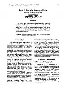
2. Justification and Introduction to Guidelines This report deals with issues that originate from the use of digital tools, whether they are sensors, actuators, system control software, building automation systems, automatic data access protocols, or any one of the myriad of computer hardware and software that find their way into HVAC equipment. The abundance of data that originates from these devices brings to the fore several challenging issues: standardization, formalization and interoperability of commissioning (Cx) data. Figure 2.1 shows how current manual practices in the building sector compare to those that digital tools and practices provide. The saw-tooth shaped (blue) curve indicates the expenditure of resources in the manual mode, over time. Each sharp increase marks a shift from one stage of the building delivery process to the subsequent one. The resources used to develop information are often in formats suitable only to the current stage that do not support work in the following stages. Each time a new stage begins, there is a sharp increase in the committed resources. The smooth (red) curve depicts the resources used in the same building delivery process with digital tools and practices, in which data representation is interoperable, that is transferable from one stage to the next, with ease. In this case, the commitment of resources is less than the manual mode owing to the reuse of data represented early on, in the later stages. These two modes of practice present the following tradeoffs: either pay in smaller amounts but frequently throughout the building delivery process or pay a lot, up front while paying less overall, due to the diminishing need for additional resources, in the later stages. The fragmented building delivery process and the multitude of consultants from different disciplines participating in the process insure a multi-dimensional (along the time and specialization dimensions) fragmentation of the data models and flow diagrams used in Cx. This is in addition to the variations that are endemic when considering practices along the intra-national realm. Figure 2.1 shows how information and data accumulation in each phase of building delivery first builds up but then is mostly discarded when the next phase commences. This “saw tooth” effect means that time and effort is wasted with the discarded data that is needed in a later phase of the commissioning process.
19
Figure 2.1 “Pay now or pay later” diagram motivating interoperable and persistent information models for the Architecture-Engineering-Construction (AEC) industry Courtesy of Andy Fuhrman, International Facility Management Association, 1 E. Greenway Plaza, Suite 1100, Houston, TX
“Historic” information and information from co-lateral areas of specialty can save time and effort in carrying out current tasks. This requires that interoperable, persistent and accurate data as well as process models are made available to the CxA. Several questions can be posed to underscore these properties.
How can we represent this data in a way so that it can be persistently and accurately stored and retrieved in digital devices? This is the problem of formalization.
How can we normalize these representations so that different devices can understand the semantics underlying these representations? This is the problem of standardization.
How can we represent this data so that different data processing equipment, hardware, and software can correctly interpret data originating from other devices, and vice versa? This is the challenge of interoperability.
While these are deep and persistent challenges which are not likely to be resolved during the span of a generation of digital devices there are many areas of digital application that have met these challenges within the span of a decade or two. Word processing, cell phones, and internet are some of the examples which are broadly used in daily interaction and communication where standards, formal models and interoperability make it possible for a variety of devices to interconnect users meaningfully and substantially. In more narrowly defined professional areas, similar goals have been achieved. These include BIM, or computer aided design, GIS, or geographic information systems, computer aided management and administration, and banking and finance management systems. It would be unthinkable to remove digital aids from these domains of application without causing all but ultimate chaos in these sectors. In a recent conference held in Berlin (2008) a room full of commissioning experts and academics, when asked, indicated that only 2 out of about 50 would be affected by a lack of access to digital technology in carrying out their tasks in the field of Cx. This is in stark contrast to other fields in the building sector.
It is important to verify the performance of HVAC systems and optimize the operation of systems in order to save energy. Since verification and optimization requires significant time, cost, and professional knowledge about the equipment in HVAC systems, many digital support tools have been developed in order to reduce the labor required for commissioning. However, these tools are not frequently used in the actual commissioning process. This is partly because the information needed when the tools are applied to an actual building (e.g., design drawings, performance statistics of building equipment, and operation data measured by sensors in the building) are not rationally organized. In this context it is difficult to obtain the necessary information for Cx. For the promotion of the use of these tools in Cx, it is important to develop a method by which to manage and organize the information rationally, through the building life cycle. The work done in this Subgroup of ANNEX-47 addresses the challenges that would take Cx to the next level of digital applications. To accomplish this, we had to address two application domains: Flow Charts and Data Models.
Flow Charts are representations that connect states and transitions of information and control over time (Appendix A8.2, A8.6, and A8.7). They capture information about events, actions and transitions.
Data Models are the corollary to this type of representation. They capture the steady state information about equipment, devices, their setting shown as “object entities” and their attribute-value information (Appendix A8.1 and A8.4).
In the following sections we report the state of the art in several national settings around the globe regarding Flow Charts and Data Models as they influence the commissioning of advanced and low-energy buildings; starting with North America, moving on to Europe and concluding with Asia. Before we go into the specifics of how Cx data and processes are used in each national context, there are two issues that apply to these national sections that are best addressed at this point: Integrated Definition diagrams, and source of national reports.
22
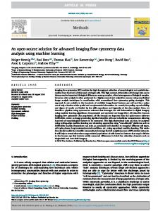
Integrated Definition diagrams (IDEF) systematically and hierarchically describe the internal information flow and the calculation algorithm of a process. IDEF methods come in different formats addressing representational aspects of products, processes, requirements, and the like. IDEF0 is a widely used process modeling method designed to model the decisions, actions, and activities of a system. It aims to analyze and communicate the functional perspective of the system. As shown in Figure 2.2, the IDEF0 diagram has a simple graphic representation consisting of boxes and arrows. The meaning of an arrow is determined by the semantic associated with the side of the box to which they connected (left side: INPUT, top side: CONTROL, right side: OUTPUT, bottom side: MECHANISM).
Figure 2.2: Integrated Description Method of IDEF0
The IDEF0 is useful in the data models and flow diagrams of Cx, for the following reasons.
Adopting a standardized modeling method in developing commissioning tools is very important because it greatly reduces the time or cost of future data modification. IDEF0 is one of the best methods for standardization because of its wide use.
Compared to other modeling methods the simplicity of the IDEF0 structure helps tool users to easily understand what the functions and needed information of a tool is even if they have little knowledge about IDEF0.
23
A method to describe clearly a Cx functionality using IDEF0 is can be based on the following steps (Figure 2.2) which describe:
the operational data that is variable with time is as INPUT.
the information about the building information modeling (BIM) data and the specifications of equipment, which do not vary with time, as CONTROL
the hardware and software requirement of the functionality as MECHANISM, and
the outcome of the tool as OUTPUT
The description of the tool using IDEF0 makes the algorithms to support these functionalities clear and facilitates the maintenance of tools represented by the process description.
Finally, the national reports that follow represent different sources and bases of acceptability. Some are national policies and practices that have the official stamp of approval by a government and its legislative powers. Others have the backing of research teams working on the problems they address and tools that they develop for many man-years and by top experts in the field. Others are a combination of the two. Belgium and the Czech Republic report on the National policies and practices. The German report on the other hand is mostly reliant on research done by practitioners and researchers in the area. The NORTH AMERICA, Japan, and Hong Kong reports base their findings both on existing national standards as well as specific research done in the area.
24
3. Flow Chart and Data Model Practices in North America: USA and Canada Cx data is readily found in component tables, relational diagrams, and other manually maintained notations. This is the current form of the Practice in North America. On the other hand computable forms of representation are also found in relational databases, and other proprietary systems and research prototypes such as the Diagnostic Agent for Building Operations (DABO, Choiniere, 2008), LBNL FPT analysis tool (LBNL, 2004), Universal Translator (UT, Stedl, 2007), and Automated Demand Response (ADR, Kiliccote, S. and Piette, M. A, 2008). The principal technologies used in the field, outside of these specialized software products, are the commercially available word processing, spread sheet and data base systems. The most comprehensive document that describes the flow of information and decisions in Cx is the ASHRAE Guideline 1-1996. We include a graphic representation of the processes described by this standard, in Appendix A8.1 and discuss them further in Section 3.2. Furthermore, we provide an example of the UML (Uniform Modeling Language)-based object class representation developed for Cx of the Air Handling Unit (AHU), in Appendix A8.1, and a simplified version in Figure 3.1. UML is a prevalent software engineering technology that captures user requirement information for business and industrial applications. Ultimately the representations in the Cx field will rely on such representations and standards developed for building information modeling (BIM), industry foundation classes (IFC), and other AEC specific software models. Figure 3.1 shows the principal (top level) categories of data essential for Cx that include all physical entities and events, all actions, tasks, and methods used in Cx.
Figure 3.1 Simplified Object Class Diagram (UML) of Cx Data Model based on ASHRAE and other sources.
25
Figure 3.2. Normalized Air Handling Unit.
Component object indicates that Equipment is made up of components. Equipment and Event are interlinked by System Context Inspection and Functional Performance Test procedures. This means that these procedures perform actions, step by step that involve the equipment and its components. Components on the other hand inherit properties like Product_ID information, Drawing_tag where the specification information resides, and Location, includes the physical place specifications of the element. This diagram which is in UML notation can be expanded indefinitely to include all equipment, components, their attributes, and all associated methods or procedures, as shown in Appendix A8.1 for the HVAC unit. The HVAC unit we have been modeling is shown in Figure 3.2. The UML representation allows one to define, as if in a dictionary or encyclopedia, all of the normally expected parts, types, attributes, and values of systems. The Data Models provided above are an illustration of the type of formal representations that are available in research and practice, in the North America. Based on a broader analysis of available building information models in the North America, we can make the following more general assessments of the Data Models relevant to the Cx field. An expanded version of the descriptions we include below can be found in Appendix A8.4. There are two general approaches to building product modeling. The first approach is employed by aecXML and AEX. These technologies organize the information as a thin layer of common domain components, which are necessary for the efficient communication between applications. However in this approach, limitations of XML technology prevent the creation of effective representation of building related data representations. The second approach, which originated in Europe and is also prevalent in North America, is represented by STEP and IFC. These technologies aim to capture the entire domain information and represent it in the model. In this approach, it is critical to maintain the relationships between entities and the integrity of the entire model when transmitting specific parts of a model to applications.
Both models follow an object-oriented approach for representing building information. They all identify building components as entities with attributes. These models have an underlying modular structure in which information is encapsulated in smaller subsets. In all models, building data is organized in levels where generic and domain specific data is separated. Generic data is sorted in resource levels and made available to other models. The IFC effort aims to capture information related to a building’s lifecycle and their relationships to each other. It represents the information in a hierarchical order from abstract to specific and provides a means for sharing the entire project stored in a model among diverse project participants. aecXML complements IFC’s capabilities by providing support to business related interactions over the Internet. In comparison to IFC, information in aecXML is flat; there is no hierarchy between entities. Since its main concern is data exchange, the data in aecXML is structured and packaged in a transactional context. While data exchange in IFC is done over a neutral file, in aecXML it is through message exchange over the Internet. During the model development process IFC, aecXML, and AEX follow a process oriented method. They first define industry processes from which the domain information is going to be extracted. IFC, aecXML and AEX utilize process models in this phase. None of these models specifically focus on building evaluation or commissioning. When IFC, AEX, and aecXML are used to model HVAC related data, the transfer of information is only partial. AEX’s cfiXML has a similar approach for data modeling, but its focus is narrower than aecXML. AEX is concerned only with building’s mechanical equipment.
3.1. Performance Metrics for Data Models in North America Product models of Cx, include a variety of potential representations including state diagrams, Flow Charts, decision trees; Computable (TTB review): algorithms (software), lambda-calculus; hybrid: spread sheets, use cases, and test cases. While we will not review each of these methods in detail, it should suffice to say that these methods are intended to:
represent a comprehensive and robust ontology of Cx; an ontology deals with questions concerning what entities exist and how such entities can be grouped, related within a hierarchy, and subdivided according to similarities and differences
28
provide flexibility for adaptation to changing contexts like building type, life-cycle stage, country of location, and so on.
allow for expandability and just in time modeling of data types and their attributes, including mapping between flows (process) and data (product) modeling
provide interoperability between different digital and manual platforms
persistence and seamless transition between lifecycle stages
evolve with changes in technology and practices, over long periods of time
3.2. Flow Charts and Process Models in North America Cx processes are documented in natural language based descriptions and other manually maintained notations of system inspection and Functional Performance Testing [FPT] of Cx equipment. This is the current form of the practice in North America. On the other hand, computable forms of representation are also found in relational databases, and other proprietary systems such as DABO, UT, and ADR.
Programming Cx
Design Cx
Construction Cx
PostConstruction Cx
Figure 3.3. A simplified Flow Chart of the ASHRAE Guideline 1-1996 for Cx
The principal technology analyzed in this section includes DF (Data Flow) and IDEF (Information Definition) diagrams, some of which has been developed and tested in the research work conducted at Carnegie Mellon University. Once again, in this section, a simplified version (Figure 3.3) and a detailed version (Appendix A8.2) of a Cx Flow Chart based on the formal descriptions in ASHRAE Guideline 1-1996 are presented. In the Program Phase, the needs of the occupants are established the first information set that is needed to design and evaluate a building’s HVAC performance,. The initial criteria of evaluation are determined and the commissioning team is selected. The key documents in this phase are the Design Intent and the Commissioning Plan. In the Design Phase, the concern of the commissioning agent (CxA) is to develop the design review which checks the operability and maintainability of the systems, the
29
clarity in the sequence of operations, and the ability to commission the designed system. The key document produced is the Commissioning Specification Report. In the Construction Phase, there are different levels of involvement according to the project scope and the owner’s expectations of the Cx process. The commissioning provider’s role is to review submittals, observe the construction process, and modify the commissioning plan and test procedures as part of the bid documents. When the constructed system is ready for inspection the designer inspects it and the construction manager certifies the system as complete and operational. Then the construction manager starts the testing, adjusting and balancing (TAB) process. The designer approves the new system. The construction manager prepares the TAB report and submits it to the CxA. In the Post-construction Phase, all commissioning activities are finalized. Two types of tests are conducted: (1) system verification and (2) functional performance tests. System verification confirms HVAC system checks, the operation of automatic control systems and the accuracy of TAB reports. It verifies that all components, equipment, systems and interfaces between systems operate in accordance with the contract documents. Functional performance testing checks the performance of the HVAC system. During these tests the commissioning provider verifies that the correct equipment is installed and whether or not it, is operational, and properly balanced. In this phase, the training of O&M personnel is also completed. If there are deficiencies reported during this phase, the construction manager makes the necessary corrections and the system is re-tested. The key documents produced include: Verification Report, Functional Testing Report, and System Manual Also findings from detailed observations of HVAC Cx practice and various interviews with practitioners in this area have been included. The Cx process Flow Chart is important for three reasons. First, it shows how people interact with each other during the Cx process. Second, one can track how and what kind of documents are produced in this process and how they evolve throughout the Flow Chart. Third, it helps identify the type of data used in Cx, which needs to be modeled. The model is also beneficial for evaluating the ASHRAE guideline in comparison to actual building Cx practice, particularly because it illustrates loops, parallel actions and some missing tasks
30
between phases. Building the Flow Chart has been helpful in relating different Cx procedures from different stages of the building lifecycle. ASHRAE’s Cx description is used as a starting point for identifying the Cx Flow Chart. This reveals a well-structured method that shows Cx activities step by step. This method aims to provide adequate information for the maintenance after the building is completed. However it does not present the details of the flow of the Cx process and its connections to different stages of building delivery, maintenance and operations. ASHRAE also requires full system training for the building’s operations and maintenance personnel. They are required to receive the entire documentation of the HVAC structure showing how the system is designed, installed, and intended to operate. CxA is defined as an employee of the owner who represents his needs and is expected to be a qualified specialist with appropriate experience and independence from all other actors. CxA would be responsible for verification and execution of the FPT; and organizing the Cx procedure. In the ASHRAE guidelines, Cx is defined as a five part process: program phase, design phase, construction phase, acceptance phase, and post-acceptance phase. They recommend that Cx should be started early in the programming phase so that it can control and document the flow of information. Finally, in comparing Flow Chart models between the practices that exist internationally, it became clear that the Japanese professional society SHASE (Society of Heating, Air-conditioning and Sanitary Engineering), which is the equivalent of ASHRAE in Japan, has a similarly documented process description. Taking ASHRAE as a benchmark, a comparison between these two process descriptions of Cx, which is included in Appendix A8.3, has been conducted.
3.3. Performance Metrics for Process Models in North America Flow Charts and process models of Cx take a variety of forms, such as FPT protocols, systems inspection; computable TTB review (Tax and Trade Bureau): IFC, parsers, mapPers; Hybrid: IDEF0, IDEF3. These representations are intended to:
31
represent a comprehensive and robust process description of Cx
provide flexibility for adaptation to changing contexts like building type, life-cycle stage, country of location, and so on.
allow for expandability and just in time modeling of process flows, including mapping between Flow Charts (process models) and data (product) models
provide interoperability between different digital and manual platforms
persistence and seamless transition between lifecycle stages
ability to adapt to changes in technology and practices, over long periods of time
3.4. Summary Findings and Recommendations for North America Flow Charts – ASHRAE vs SHASE are each good on their own way (comprehensive, detailed); leave them alone; other countries would be encouraged to adopt or develop versions of their own; these are good examples to emulate Data Models – little exists in this category except for IFC STEP-21 representations. There are other avenues that do not require international collaborations, like IDEF3 representations for describing Cx-FPT (Appendix A8.5). In addition some formal language like Backus Naur Form (BNF) could be useful in testing the logic of process descriptions – automated applications would be welcome Expand energy auditing and green building movements, such as LEED certification, (should) include Cx as part of their requirements; this will encourage practice by piggybacking on existing process product models BIM and its effect on the AEC industry must be anticipated – emphasis should be placed on semi-automated hybrid (manual + automated) and computational tools Much work needs to be done in this area. While automation of Cx is picking up steam through many independent efforts at building computer based Cx decision support software (Appendix A8.6), there is still a lot more work to do towards the goals of formalization of data and interoperability of processes. Future challenges include defining user parameters and preferences, formalization of data, and interoperability of processes. User groups are diverse and varied in their needs. There are in
32
surmountable difficulties with gathering and unambiguously representing user parameters and preferences. Furthermore there is little motivation to devote resources to such tasks until they become critical for the engineering task, at which time there is little time or motivation to complete these tasks. Data comes in different forms; in particular, data representing natural language input or devices that are non standard and comply with proprietary requirements rather than universal standards. Processes that are required by various phases of the building delivery and operations continuum are fragmented by data needs and formats. As one professional completes their task, most of the data they have processed has to be discarded or cannot be used by other professionals performing others task. Interoperability models and software can improve the usability of data and formats between phases of the building lifecycle. However, common obstacles like resistance to standardization, large data bases and proprietary information prevent software developers from making significant advances towards interoperability. .
33
4. Flow Chart and Data Model Practices in Europe Several of the European national practices and regulations require the Energy Performance of Buildings Directive (EPBD) as the basis of their standards. EPBD is based on the Directive 2002/91/EC of the European Parliament and Council on energy efficiency of buildings. The directive was adopted, after a lively discussion at all levels and with overwhelming support from Member States and the European Parliament, on 16th December 2002 and entered into force on 4th January 2003. It is considered as an important legislative component of energy efficiency activities of the European Union designed to meet the Kyoto commitment and responds to issues raised in the recent debate on the Green Paper on energy supply security (European Commission, 2000). The EPBD provides a general framework for the calculation procedures. A mandate has been given to the CEN committee to develop appropriate calculation procedures to support Member States in the national application of this article. This theme includes the assessment of the relevant EN (CEN) and EN ISO standards the way they are or will be implemented at national level, options for quality assurance of calculation methods, differences between methods or data input for new versus existing buildings, legal aspects (e.g. national versus CEN options), practicability as "simple" as possible and yet sufficiently accurate and distinctive, methodologies for innovative technologies. EPBD software is available to automate some of these requirements. These are based on a large number of building and installation characteristics. It calculates the Uvalues, the average insulation level (K-level) and the E-level (Primary energy consumption) of the building and controls compliance with energy-efficiency and indoor climate requirements. It also checks the minimum ventilation requirements. EPBD software is widely used in the Czech Republic, Belgium, and Germany. For instance, in Belgium, as part of the process of demonstrating compliance with required energy performance, assessment of the energy performance of design of new dwellings is mandatory in the Brussels Capital Region, Flemish Region and Walloon region.
34
4.1. Belgium Since the implementation of the European Directive 2002/91/EC and since the introduction of project-related energy performance requirements (e.g. the passive house concept), problems about guaranteeing (energy) performance and information flow among building partners and quality control have become more significant. The EPBD and passive house certification are conducive to being used to improve product and process modeling in commissioning for existing and new buildings as they are accompanied by a process of certification. For most buildings with a building permit, requirements are set for the energy performance and indoor climate (EPB requirements). The reporting of these requirements is undertaken by EPB reporters using EPB software or PAE software (procedure d’avis énergetique). Mandatory inspections of boilers and advisory support are mandatory since 2009. Through the use of EPBD software U-values, the average insulation level (K-level) and the E-level (primary energy consumption) of the building and controls compliance with energy-efficiency and indoor climate requirements are evaluated. The E-level cannot be used as an indicator for passive houses. Therefore PHP passive (PHPP) software is used for very low energy buildings (Table 4.1.1) PHPP software has been created as a design tool for passive housing and tertiary projects. It‘s used for the certification of projects built according to the passive house standards. 4.1.1 Product Models For EPBD three types of requirements exist:
Thermal insulation: maximum thermal transmittance of walls (U) and the building (K)
Energy performance (E)
Indoor climate: ventilation system and minimal risk of overheating
Application of these requirements depends on:
the kind of construction
purpose of the building
Table 4.1.1 gives an overview of the EPBD requirements in the Flemish Region.
35
A “normative” building is based on the K45–E100 Flemish EPBD requirements. Energy performance requirements for “passive” and “active” buildings are much higher. Space heat demand of 15 kWh/m2·year and the pressure test n50< 0.6 h-1 are considered as minimal values. The final primary energy demand has to be ( 800m³) Enlargement (min. 1 residential building)
residential
Offices and schools
Other purpose
industry
Thermal insulation
Max. K45 Max. U or min. R
Max. K45 Max. U or min. R
Max. K45 Max. U or min. R
Max. K55 Max. U or min. R
Energy performance
Max. E100
Max. E100
-
-
Indoor climate
Min. ventilation Min. risk overheating
Min. ventilation
Min. ventilation
Min. ventilation
Table 4.1.2: Matrix comparison between energy performance levels with EPB and PHPP
Walls Wall extension Roof extension Floor extension Floor attic Glazing
Cold Bridges wall/floor existing/new T Ventilation h Heating system e
Airtightness: n50 EPBD c PHPP u energy demand for net r
Common practice
0.4 50. 3 0.3 90.35 0 29 0.2 3 0.1 3 ψ=0.2 6 ψ=0.05 6Sys. A boile r solar panels 9.3 h-1
0.3 1 0.2 4 0.1 40.32 0 21 0.2 31. 1 ψ=0.1 9 ψ=0.0 4Sys. A Condensing boiler solar panels 4 h-1
[W/m²K]
Wall existing building
heating
Normativ e
[W/m²K]
Low energy
[W/m²K]
0.2 4 0.2 4 0.1 4 0.2 0 0.2 31. 1 Sys. D Condensing boiler solar panels 1 h-1
Passive house
[W/m²K]
0.1 3 0.1 10.13 0 11 0.1 20.17 0 160. 6 Sys. D Ground heat + exchanger heat exchanger solar panels 0.6 h-1
K45 - E98
K35 - E67
K30 - E38
K20 - E23
118
77
43
15
kWh/m² a
36
The currently used E level is not a good measure to differentiate passive houses. E.g. the same passive house project can achieve an E level from 18 to 35. Differences are due to the possible choice of solar thermal and/or photovoltaic panels. A better EPBmeasure for passive houses might be an E-level (after adaptation of the calculation procedures) without taking into account renewable energy. In addition some passive house projects have an increase of E level because the current EPB calculation procedures do not take into account passive cooling techniques like earth-air heat exchangers (overheating is punished) for the evaluation of summer comfort. The actual passive house certification scheme in Belgium is based on the final outcome. Certification of passive house projects, in the future, should be incorporated as part of the existing procedure for the EPB- Certification (Section 4.2). 4.1.2 Process Models Since the implementation of the EPBD in Flanders (Belgium) efforts have been made to avoid the classical fragmented information flow during the building process. The current use of EPB/PHP standards for Cx and RCx of buildings is described in the IDEF0 diagrams below, in Figures 4.1.1.a-d. For an explanation of IDEF0 see Figure 2.2. Design Phase In most cases the building designer does not have the knowledge of the PHPP tools. A passive house energy consultant is usually assigned to the project. The energy consultant will provide passive house design advice, PHPP calculations and recommendations for products and specification of technologies.
37
Implementaton EPB of D Passive Standar House d Owner requirements Site
Desig n
plan Certifie - lambda d -value energy efficiency data
Energy Agency Passive Platfor House m
BIM Model A
Technical specifications Exclusion / Selection criteria Award criteria Onbuilding site practices
Constructio n B
As Built C
Nod e:
Figure
Title:
Thermal analysis bridge software PHPP EPBsoftware Energy software consultants Drawin T g ool s standards for Cx and RCx of Use of EPB/PHP buildings
Implementatio pla n Ris n a k ssessmen Tendet rdocument s
EPB Certificate Passive House Certificate
No.: ROOT - A0
4.1.1.a IDEF0 illustrating the use of EPB/PHP standards for Cx and RCx of buildings
Figure 4.1.1.b IDEF0 illustrating the use of EPB/PHP standards for Cx and RCx of buildings
39
Figure 4.1.1.c IDEF0 illustrating the use of EPB/PHP standards for Cx and RCx of buildings
40
Figure 4.1.1.d IDEF0 illustrating the use of EPB/PHP standards for Cx and RCx of buildings
41
Construction Phase Building contracts are awarded on the basis of award criteria applicable to the content of the tender, in which case the contract is awarded to the “most economically advantageous
tender”
under
the
best-value-for-money
procedure.
For
the
commissioning of passive houses the preferred award procedures are the performance-based bidding procedures, open or restricted calls for tenders, the design contest, the negotiated procedure with or without publication and the competitive dialogue. When building a residential passive house concept the required on-site practices and know-how to achieve low air-leakage, proper installation of insulation, windows, heatrecovery ventilation system, etc. are much more rigorous than typical on-site EPB construction practices in Belgium. Due to the lack of experience of contractors to build to much more demanding requirements of the passive house, there is potentially a high risk of the house claiming to be a passive house having higher energy demand than the passive house standard. As Built New dwellings must provide a specific numerical building energy and indoor climate rating i.e. ‘E level’, and internet based declarations. The EPB software is used to produce E levels and advisory reports for buildings requiring a building permit. These are produced by an accredited EPB reporter who is registered in the regional database of assessors.
When a passive house is built, the building owner requires an air-tightness test (conducted by an independent testing company) and the building should achieve the air-tightness level required by the passive house standard.
A thermographic camera (IR camera) could be used to indicate areas where thermal bridging occurs. At present, this is very rarely the case in Belgium due to a lack of equipment, and know-how and the cost associated with testing.
When tests and final calculations are completed, the building owner can apply the Passive House platform, for a Quality Approval as a Passive House.
4.1.3 Future expectations and Recommendations As part of the Directive, a Building Energy Rating (BER) certificate, which is effectively an energy label, will be required at the point of sale or rental of a building, or on completion of a new building. The certificate must show the total energy use for space heating, water heating, ventilation and lighting expressed as primary energy use in kWh/m2/yr, in Scale A (A1, A2, A3); Scale B (B1, B2, B3), etc. Figure 4.1.2: Building Energy Rating (BER)
certificate from EAP procedure
The actual certification procedure of passive house projects will be established as part of the existing structure for the EPB-Certification. This will include the requirement that the building owner submit a set of required documents to the Accredited EPB reporters. The documents will include:
PHPP calculations,
PH specific detail drawings (showing areas for potential thermal bridging),
Product and systems specification (manufacturer declared specification for insulation, glazing, ventilation equipment, low-energy lighting etc.),
post-construction air-tightness test results, and
possibly images with an IR camera to confirm the quality of insulation placement and/or airtightness.
The accredited EPB reporters will need a good knowledge of the passive house concept, energy performance, design principles, energy and testing standards required to achieve the passive house standard. The existing EPB and PHPP calculation tool will have to be modified. Knowledge of the passive house standard and energy requirements is not seen as a barrier.
43
Building information models (BIM) are a promising way to solve a lot of problems in the workflow, the information exchange and the data management during the whole life-cycle of a building. This becomes especially important in passive house projects, due to increased complexity and the need for a very strict quality assurance process (commissioning). 4.1.4 Analyzing the workflow A first analysis of the workflow of a project team designing Passive houses was performed. Starting from ideas that are visualized with SketchUp [SketchUp, 2008] and discussed with the (potential) customer, an architectural model is created in REVIT Architecture [REVIT, 2008] (Figures 4.1.2-4.1.3). It was observed, that due to the stricter requirements of the Passive house standard and the importance of an integral design, including solar gains, heating and ventilation systems, a lot of data is created, communicated and modified, very early in a project. The design of the architect is guided by results from different tools for energy performance analysis used for passive houses, e.g., Flemish EPBD, PHPP, steady state 2-D thermal bridge analysis and more research oriented tools for dynamic heat and moisture simulation. Due to limitations of the existing software tools, information has to be re-entered several times, often communicated by e-mail or phone. This leads to another challenge: keeping track of all the changes occurring during the design process and managing the consistent updating of all the logically inter-related but physically independent project data. Also the reuse of data from earlier projects and from external suppliers, e.g. manufacturers of components and building materials, is still difficult. One serious bottleneck is the fact that the tools for energy performance analysis (PHPP, EPBD) still have text based input without any direct link to the BIM. The information about heating, sanitary hot water, and ventilation has to be entered manually in the EPBD and the PHPP software, since no electronic product catalogues are available. In a final step the installations have to be designed, without reuse of existing data and without any automatic check for consistency.
44
Figure 4.1.3: BIM model in Revit
Figure 4.1.4: 3D-view from IFC-model with integrated EPB analyses
46
Figure 4.1.5: Data-view from IFC-model with integrated EPB analyses
4.1.5 Improving the workflow and the product quality A fully data-centric approach based on an open standard such as the IFC [IAI, 2008] leaves the choice of the best (or most affordable) tool for each task to the user, while still being able to exchange the necessary data directly with all the other team members. (Figure 4.1.4 and Figure 4.1.5Figure 4.1.) Beside the use of the IFC, a thorough understanding of the level of abstraction in each of the partial models and their mutual dependencies is essential. A detailed description of the information needed as input for each task and a similar description for its results has to be made and published. A good example for such an effort is a document published by the German section (3.3.2) of the IAI [IAI_G, 2006]. Similar documents can be created based on passive house projects. They will serve as a use-case for software-design, as an example of “good-practice” and possibly as part of a project contract: with such a document the future owner of a building will not only receive a high quality building, but also a reusable BIM for facility management and modifications during the entire life-cycle of the building. For the necessary data exchange and consistent change management, an IFC model server seems to be the best solution. [R. Verstraeten, UGent]. The development of software tools for passive house design needs to be integrated into ongoing research on the topic in the construction industry, see for example the European project “InPro” (2007). 4.1.6 Conclusion After several years of research activity, the IFC is gradually becoming a stable and practical foundation for BIM. It is clear that a close integration of the tools for energy performance analysis (PHPP and national/regional EPBD) is of vital interest for a more widespread adoption of the Passive house standard. Such a solution reduces significantly the cost for the more complex design process of a Passive house and will increase its reliability and the quality of the final product. Further research is needed, to create Use-Cases for the development of the next generation of software tools, to adapt the workflow of design teams and to deliver a reusable, information rich, building model to the client.
4.2.
Czech Republic
The calculation method for energy consumption in the Czech Republic is based on the delivered energy for standard indoor and outdoor conditions. This is the actual energy consumed or the expected amount of energy for the fulfilment of various demands related to the standard use of the building. In particular, heating, hot water preparation, cooling, treatment of air by ventilation and modification of parameters of the indoor environment by air conditioning system and lighting. The basic process of the calculation is commonly divided into two stages:
Calculation of energy demand of the building, or its parts – zones; this means the calculation of heat losses, and heat gains, required in each space in order to maintain specified internal conditions.
Calculation of energy consumption (building, or parts – zones, according to the energy demands); this means the calculation of the energy required by the energy systems (boilers, AHU units, DHW systems, lighting, etc.) needed to provide the necessary heating or cooling, or humidity control.
The energy demand is calculated on the basis of the standard use of the building. This is the use in accordance with normative conditions of indoor and outdoor environment and operations of the building subject to the valid technical standards and other national regulations. The calculation method is based on the Simplified Dynamic Calculation. In SDC, the energy demand can be calculated from monthly, daily and hourly simplified values. Hourly calculations are better to represent the complexities of HVAC systems, mainly because of cooling performance. In the degree-day method (DDM), which is well-established and easily used for heating and cooling energy calculations of relatively simple buildings, is not used. Empirically, there are extensive correlations between cooling energy use and cooling degree-days for some buildings and systems. For cooling demand it is not possible to use average month temperatures because average temperatures are lower in summer months than the indoor temperature, which means that is not the cooling demand. In this case, only energy demands for the domestic hot water and lighting within monthly calculation methods are considered.
49
Calculation of energy demand on heating is based on the calculation of the building energy demand for each zone. According to the energy demand, this method calculates the energy consumption. Energy demand for space heating Qdem,NH and cooling demand Qdem,NC is calculated according to CSN EN ISO 13 790 and CSN 73 0540. The basic calculation includes transmission losses QT and ventilation losses QV. The calculation method also includes heat gains QG,H (internal Qi and external Qs) - internal heat gains from occupants ΦI,OCC, appliances Φl,APP, lighting influences ΦI,LI and final energy demands of the adjacent zones Qi,u,l. Heat gains are determined by heat production multiplied by the fraction of the time t when the occupants/appliances are present in the zone. Energy demand is reduced by a constant value that is dependent on the external and internal gains. 4.2.1 NKN: The National Calculation Tool of the Czech Republic Based on the method described above, a calculation tool is provided. This calculation tool is created in a spreadsheet on the basis of combining a compact procedure with access to an easy test of the calculation method. The national calculation tool calculates the energy demands (heating, cooling, domestic hot water systems, lighting, etc.) of each space in the building or zone according to the activity within. Table 4.2.1 Input to the NKN Information
Source
Building geometry, areas, orientation, etc.
Reads from drawings or direct measurement
Climatic data
From the internal database calculation tool
Occupancy profiles for activity areas assigned to each space
For consistency, these come from an internal database – by choosing building type and activity for each zone
Building envelope constructions
Inputs parameters directly (“Inference” procedures may be used for energy certification of existing buildings)
HVAC systems
Selects from internal databases or input parameters
Lighting
Selects from internal databases or inputs parameters
50
NKN includes different standardized profiles of uses that may require different temperatures, operating periods, and lighting standards. It calculates the heating and cooling energy demands by carrying out an energy balance based on climate. This is combined with information about system efficiencies to determine energy consumption. Energy used for lighting is calculated for each zone and domestic hot water.
It is calculated for the whole building. . Input data to NKN requires
information from the following sources: Setting a building in NKN includes the following steps:
enter general information about the building, owner, certifier, and select the appropriate weather data;
build up a database of the different forms of constructions and glazing types;
create the zones in the interface and enter their basic dimensions;
define the envelopes of each zone – walls, floors, ceilings, etc. their dimension, orientations, the conditions in the adjacent spaces, and the constructions used to be defined along with the air permeability of the space;
define the HVAC (heating, ventilation, and air conditioning) systems, the DHW (domestic hot water) systems, and any SES (solar energy systems), PVS (photovoltaic systems), wind generators or CHP (combined heat and power)generators used in the building; define the lighting system and ventilation characteristics of each zone and assign them to the appropriate HVAC and DHW systems.
51
Figure 4.2.1 NCT user interface in MS Excel showing the schematic of building system capabilities, setpoints, and energy consumption
Table 4.2.2 Annual energy consumption, in KWH/m2 in the building classification (new building- A-C accepted) Building type
A
B
C
D
E
F
Family house
< 51
51 - 97
98 - 142
143 -
192 - 240
241 - 286
Apartment
< 102
102 -
201 - 294
295 -
390 - 488
489 - 590
>
< 62
62 - 123
124 - 179
180 -
237 - 293
294 - 345
>
< 109
109 -
211-310
311 -
416 - 520
521 - 625
>
Education
Sport
< 53
53 - 102
103 - 145
146 -
195-245
246 - 297
>
Shop, market
< 67
67 - 121
122-183
184-241 242 - 300
301 - 362
>
Hotel, restaurant Office Hospital
G >
52
Figure 4.2.2 Graphical building classifications
The annual energy consumption is calculated for the following items: space heating systems; domestic hot water heating; electricity for pumps and fans (including mechanical ventilation if present); electricity for lighting. 4.2.2 Standardized profiles of use Most buildings are operated differently and as the main day period comes to an end all systems decrease in performance. This is obvious for different building types, but like results can be observed even in similar buildings that have different use patterns. For example, identical buildings, when the first one is heated to the set point temperature 20 °C and the second one meets temperature 22 °C will yield dissimilar values of annual heating energy consumption. These circumstances provides serious problem for general assessment of building performance, even in the case when comparison of different buildings is required. The only solution is standardized profiles of use. While developing the performance assessment tool, certain profiles for major building types were created. The target of each profile is to set indoor conditions that
53
meet desired quality level of an environmental zone. Basically the zone environment level set up fulfils requirements of thermal comfort, ventilation, lighting and effects related to activities, such as heat gain. This choice of constant profiles has certain advantages, especially when identical parameters for the same zone type are used in different buildings. This helps avoid underestimation of some energy consumption types, for example low lighting intensity. Generally this results in large amounts of data in each profile. These data values serve as boundary conditions for energy building performance calculations of any zone or any building. For calculation purposes the user just chooses a particular profile related to the assessed zone. Concretely, each standardized profile of use includes data groups that define operation times in a day and year, heating and cooling set point temperatures, ventilation air flow and supply air temperatures, indoor heat gains, and artificial lighting zones. Collecting necessary micro-environmental data requires complex searches through national technical and law standards. These sources include many relevant numbers; yet, due to heterogeneous building types, some data is missed. Purposefully, values from foreign standards, e.g. DIN 4799 for supply air in surgery zone definition, are used. Sources that were considered are databases of energy simulation programs, especially DesignBuilder. Presently, there are nine groups containing a total of 49 standardized profiles of use. These nine groups cover main building types, such as dwelling houses, apartment buildings, office buildings, educational buildings, health and care institutions, hotels and restaurants, sports facilities, commercial buildings and finally theatres.
54
4.3. Germany The central practice in Germany is based on the ISE procedure. The Fraunhofer ISE uses a 4-step procedure for a cost effective performance analysis of buildings in the BuildingEQ project founded by Intelligent Energy – Europe (IEE). This procedure follows a general top-down approach and is described in detail in (Neumann, 2008). The idea of this top-down approach is to put effort in form of measurements and analysis only where and when necessary. The transition from one step to the next should only be performed if certain criteria are fulfilled. Flow Charts are presented for each step that guides the analyst through the process in order to “standardize” the analysis.
Steps 1.
Benchmarking (Operational Rating)
2.
Certification (Asset Rating)
3.
Optimisation
4.
Regular Inspection
Benchmark (Operational Rating)
Operation without faults and optimized & Savings calculated
Certification (Asset Rating) + Availability of hourly data 1
2
3
4
continuous commissioning
Time Figure 4.3.1 Scheme of the 4-step procedure on a time scale
Furthermore, this 4-step procedure is based on the following assumptions: o
Persistence of energy efficient operation of a non-residential building can only be achieved by ongoing commissioning
o
Ongoing monitoring (based on hourly or sub-hourly measurements) is therefore crucial
55
o
Installation of additional measurement equipment is carried out only if necessary for further analysis.
o
All standard analysis should be based on a predefined minimal data set.
The predefined minimal data set plays an important role in the process as a major part of the analysis is based on it. Table 4.3.1 Minimal data set of measured data [*h= hourly] item
Measured value
unit
min. time resolution*
remarks
consumption
total consumption of fuels
kWh
h
e.g. gas, oil, biomass
total consumption of district heat
kWh
h
total consumption of district cold kWh
h
total consumption of electricity
kWh
h
total consumption of water
m³
h
outdoor air temperature
°C
h
outdoor rel. humidity
%
h
global irradiation
W/m²
h
indoor temperature
°C
h
one or more reference zones
indoor relative humidity
°C
h
one or more reference zones
Flow / return Temperatures of main water circuits
°C
h
in the building, not a district heating system.
supply air temperature of main AHUs
°C
h
only if supply air is thermodynamically treated
supply air relative humidity of main AHUs
%
h
only if supply air is humidified / dehumidified
weather
indoor conditions
system
The minimal data set was consciously chosen. It is believed to be the minimal amount of measured data that is necessary to facilitate a rough overall assessment of the performance of the whole building. Concerning the availability of stock data and measured data similar situations are reported. Generally, the availability of high-quality stock and measured data is low especially for older buildings. The effort for gathering detailed stock data ranges
56
from less than 1 day up to 10-15 days. Besides technical difficulties and missing documentation, administrational problems (locating responsibilities, contractual and security issues) may play a major role and slow down the data acquisition process. The cost for acquiring the minimal data set is on the order of 10,000 to 30,000 EUR per building. However, this depends more on the actual state of the system (BAS available, meters available, etc.) than on the building size. General rules cannot be derived but in relation to the yearly energy costs of the buildings a static payback time of less than 2 years appears reachable - even if only 10% energy/cost savings are achieved. 4.3.1 The Details of the steps Table 4.3.4 gives an overview over the details of the 4-step procedure. The following
5.0 heat/gas electricity static payback MAX static payback MIN
350 000 300 000
4.5 4.0 3.5
250 000
3.0
200 000
2.5
150 000
2.0 1.5
100 000
1.0
Finland_bui4
Finland_bui3
Finland_bui2
Finland_bui1
Germany_bui4
0.0
Germany_bui3
0.5
0
Germany_bui2
50 000
Germany_bui1
yearly energy cost / [€/a]
400 000
static payback for monitoring / [a]
sections will describe every step in detail.
Figure 4.3.1 Estimated static payback of monitoring in demonstration buildings based on real yearly energy cost. Assumption: energy savings through Ongoing Commissioning=10%. Cost for data acquisition = 8.000 € (MIN) / 25.000€ (MAX)
Table 4.3.4. Overview of 4-step procedure Step 1
Step 2
Step 3 (a+b)
Step 4
57
Name
Benchmarking (Operational rating)
Certification (Asset Rating)
Optimization
Regular Inspection
Description
Gather basic consumption and stock data and first classification / baseline of the building performance
Asset rating according to national implementation of the EPBD, if applicable.
Analysis of the building performance, identification and implementation of energy saving measures and optimization of performance
Maintain optimized performance by ongoing (minimal) monitoring
Stock Data
minimal building description
Depending on national implementation, if applicable (otherwise see step 3)
3a: Only basic data (step 1)
No additional stock data needed
3b: Data of building and HVAC system for simplified model Additional stock data according to individual needs
Measured Data
Performance Metrics Evaluation techniques
Utility bills / own meter readings (yearly / monthly)
None
specific energy consumption / signatures
Depending on national implementation
Minimal data set
Reduce to minimum
Additional measurements according to individual needs 3a: standard analysis (measurement based)
Energy consumption as major metric
3b: standard analysis (model based) individual approaches
Further Actions
(Installation of data acquisition; only if required)
(Installation of data acquisition; only if required)
Installation of data acquisition (if not yet available)
None
Implementation of energy saving measures Outcomes
First classification + baseline (yearly / monthly)
Theoretical benchmark
Faultless / optimized operation
Deep insight in system
Energy saving measurements introduced
Identification of major energy consumers
Documentation of energy savings
Persistence of energy efficient performance
4.3.2 Step 1: Benchmarking (Operational Rating) The purpose of step 1 is to gather the most basic information about the building and its energetic performance. It relies only on data which in most cases is readily
58
available from the building owner. The data should provide a first classification of the building and a simple baseline (Appendix 8.8) The following stock data is collected, in order to classify the building and to be able to calculate specific values of the energy consumption. The data shown in the table below must be compiled: Table 4.3.2 Step 1: stock data data
remarks
General data
E.g. location and year of construction
Area / reference Values
Reference values for calculation of specific consumption, e.g. useful floor area, gross volume, etc.
Energy consumption
Annual consumption and utilization of every energy carrier delivered to the building
Water consumption
Annual consumption and utilization of water delivered to the building
Main utilization
Main utilization of the building or major building zones respectively
Tariffs (optional)
Tariffs for every energy carrier and water
For step 1, historical consumption data on the whole building level is required. The total amount of energy and water delivered to the building by the utility should be listed – if possible on a monthly basis. Besides the utility bills, manual meter readings may be available. Time specifications only mentioning the month of the reading are not sufficient. If more detailed metering data is available (e.g. sub metering for electricity or heat or data with a higher time resolution) this will be subject to step 3a. The performance indicators for step one are specific values for the energy consumption that might be displayed as specific consumption values or as a characteristic energy signature. Both can be utilized as a pre-retrofit baseline. Also, cost data can be utilised for equivalent performance metrics. Outcomes / aims of this step are:
First classification of building performance
59
Baseline (regression model) if monthly meter readings and weather data are available:
Rough insight on possible saving potentials Table 4.3.3 Step 1: performance indicators
Performance Metric
unit
Evaluation technique
Annual specific consumption
kWh/m²
Calculate the specific consumption values and
or
compare to statistically derived values for similar
(e.g. specific energy consumption
kWh/m³
buildings, to values from previous years or to
per square meter of net useful
per year
values from similar buildings nearby with
area or net useful volume)
or month
weather correction applied
Energy signature
-
If at least 9-12 month of monthly meter readings and weather data for the respective months are
(dependency of consumption on
available, a preliminary baseline can be
weather + other variables)
developed as an energy signature
4.3.3 Step 2: Certification (Asset rating) Step 2 comprises an asset rating according to the national implementation of the EPBD. This will be a more or less detailed theoretical calculation of the energy demand of the building. Therefore it is necessary to collect stock data of the building envelope and the HVAC system. Accordingly, this step will deliver deeper insight into the system and an identification of the main energy consumers. Table 4.3.3 shows the Flow Chart for Step 2. The different starting points are characterized by different availability of measured data. Outcomes / aims of this step are:
Asset rating provides theoretical target value for consumption
Deeper insight into system
Identification of major energy consumers
60
4.3.4 Step 3: Optimisation – Overview Step 3 is sub-divided into two parts (3a and 3b). Step 3 is the crucial part of the process as it includes the analysis of the building performance, the identification and implementation of energy saving measures and the optimisation of operation. Generally, this procedure is called fault detection and diagnosis (FDD) and Optimization. While faults can be described as unintentional worsening in the intended operation, optimization is targeted improvement of the intended operation or its adjustment to the currently imposed boundary conditions. In order to be able to optimise the building performance there should be no gross faults in the operation. Therefore, prior to the optimisation, fault detection and diagnosis must be performed (Jagemar, et.al., 2007). Typical problems addressed by
FDD
and
Optimization
in
existing
buildings
according
to
TRNSYS
(http://sel.me.wisc.edu/trnsys: A TRANsient SYStems Simulation program) are: scheduling
problems,
simultaneous
heating
and
cooling,
faulty
controls,
programming mistakes in the system control, not positioned correctly sensors or actuators,
deactivated
or
falsely
set
controls,
lacking
calibration,
lacking
maintenance, lacking hydraulic balancing, setpoints / resets / setbacks, staging faults, malfunctioning dampers and valves, oversizing / undersizing, components. Outcomes / aims of the step are:
Identification of energy conservation opportunities
Energy saving measures introduced
Faultless / optimized operation
Documentation of energy savings
Step 3a: Standard analysis (measurement based) Step 3a tries to transform the measured data to information about the building performance. Furthermore, faults and possible saving potentials will be identified. Appendix 8.8 shows the Flow Chart for Step 3a. This is done by two methods: Pre-defined “intelligent” visualization Rule based fault detection
61
As all analysis is based on the minimal data set, this analysis is easy to implement in any building without much knowledge about its properties. However, it requires a general understanding of operation and utilisation to formulate meaningful rules. At least 2 months of hourly data should be available for this step. If necessary the measurement equipment and recording must be installed first. If either a rule or an inspection by an expert detects “unusual” behaviour, the data has to be further analysed to find possible saving potentials. In some simple cases, this might also be done by rules. In most other cases this will be done by an expert. If it is not possible to identify a saving measure from the minimal data set, the analyst can also decide to do additional analysis or measurements. If an energy conservation measure is identified and implemented, the savings have to be calculated or measured and the baseline for regular inspection has to be adjusted. 4.3.5 Visualization For the pre-defined visualization the following chart types will be used (examples will be given in the text below): time series plot, scatter plots (XY plot), carpet plot, and box plot. In most cases scatter, carpet and box plots will be used for analysis of the data as they deliver “characteristic patterns” for the energy consumption and the system temperatures e.g. time series will be used as reference chart, in order to check the time sequence of an unusual behaviour that was detected with one of the other charts. Important tools in visualization are filtering and grouping of data. “Filter” denotes the creation of a subset of data that satisfies a certain condition. Thus, the behaviour of variables under certain boundary conditions can be studied. Filtering is also extremely important considering that there are no flow measurements. Accordingly, whether a water circuit or air handling unit is in operation can be detected by the temperatures. By “Grouping” of data according to certain conditions (e.g. heating energy grouped for workdays and weekends) different operating points can be compared. Even though the minimal data set will be recorded on an hourly or sub hourly basis, aggregation to daily or monthly values is reasonable in some cases in order to neglect dynamic effects. The following examples illustrate the issues discussed
62
above. Looking at the examples of visualization above it is obvious that the energy consumption and operation of a building produces typical “operation patterns”. For the shape of these patterns, rules can be formulated. For the daily energy signature for heating (Figure 4.3.3), the following principal rules can be established: Annex 1 The change point (the outdoor temperature at which the heat consumption becomes weather independent) should be located in the range between 10-20 °C. Annex 2 The weather independent load (above the change point) should correspond to the domestic hot water consumption (if there are no other heat consuming processes). For typical office buildings this should be near zero. Annex 3 The slope of the weather dependent part of the signature should correspond to the energetic quality and comfort of the building. Annex 4 If a setback on weekends is scheduled, there should be a clear grouping of day types in the signature. Annex 5 These rules can either be checked by the operation staff, an expert or in an automated way by rules. The Building EQ project will develop sets of such rules for the different operation patterns in a later stage. Table 4.3 gives the definition of the visualizations for the minimal data set that is done in step 3a. Note that data with different time resolution has to be derived from
heat / [kW]
Electricity / [kW]
the original measurements which are hourly or sub hourly.
Figure 4.3.2 Time series plots on hourly basis (heat and electricity consumption). Both figures show a clear difference between the operation on workdays and weekends. They also identify night set back. Finally they identify a minor error in the heating system control which did not consider the holiday on January 6th.
63
Figure 4.3.3 Scatter plots on daily basis with grouping for workdays (red) and weekends (green) Signatures for heating and electricity consumption. Both signatures show a clear difference between the operation on workdays and weekends. Furthermore the weather-dependent part of the load can be principally identified.
Figure 4.3.4 Carpet plot on hourly basis: Electricity consumption. The carpet plot shows clear weekly “patterns” that indicate the difference between night and day operations as well as between weekdays and weekends.
64
Table 4.3.4 Pre-defined visualization in step 3a for minimal data set Type of chart
Values for display
Time resolution:
Months / Weeks
Time series
Consumption and outdoor air temperature / moisture
For reference (can also be done with yearly data)
System temperatures and outdoor air temperature
For reference
Consumption vs. outdoor air temperature (“signatures”)
Identification of weather dependent and independent part of consumption and influence of utilization (scatter)
Scatterplots
For cold: additionally vs. absolute outdoor air humidity / enthalpy
Remarks
Time resolution:
Days
Time series plot
Consumption and outdoor air temperature / humidity
For reference
System temperatures and outdoor air temperature
For reference
Consumption vs. outdoor air temperature (“signatures”)
Identification of weather dependent and independent part of consumption and influence of utilization (scatter)
Scatterplots
For cold: additionally vs. absolute outdoor air humidity / enthalpy Grouping: type of day Supply temperatures (water side) vs. outdoor air temperature Grouping: type of day Supply air temperature vs. outdoor air temperature In case of AC system: Supply air humidity vs. outdoor air temperature
Identification of setback on basis of days (e.g. on weekends)
Identification of control of supply temperatures and potentially different operation modes.
Identification of control of supply temperatures and potentially different operation modes.
Grouping: type of day indoor temperature vs. outdoor air temperature In case of AC system: additionally indoor humidity vs. outdoor air humidity
Classification of indoor climate
Grouping: type of day Boxplots
Consumption per weekday
Identification of day types: (i.e. days with significantly different loads (normally: workdays weekends)
Type of chart
Values for display
Remarks
Time resolution:
Hours
Time series plot
Consumption and outdoor air temperature / humidity
For reference
System temperatures and outdoor air temperature
For reference
65
Scatterplots
Supply temperatures (water side) vs. outdoor air temperature Filter: Difference of supply- and return temperature must exceed a certain limit (e.g. 2K)
Identification of control of supply temperatures and potentially different operation modes.
Grouping: type of day Supply air temperature vs. outdoor air temperature In case of AC system: Supply air humidity vs. outdoor air temperature
Identification of control of supply temperatures and potentially different operation modes.
Filter: Difference between supply air and indoor air temperature (or humidity respectively) must exceed a certain limit. Grouping: type of day indoor temperature vs. outdoor air temperature In case of AC system: additionally indoor humidity vs. outdoor air humidity
Classification of indoor climate, identification of unusual states
Grouping: type of day Boxplots
Consumption per hour of the day
Identification of typical consumption profiles for different types of days.
Type of chart
Values for display
Remarks
Time resolution:
Hours
Carpetplots
Consumption
Identification of consumption pattern (daily, weekly, seasonal)
Supply temperatures (water side)
Identification of operation patterns (daily, weekly, seasonal)
Filter: Difference between supply and return temperature must exceed a certain limit. Supply air temperature vs. outdoor air temperature
Identification of operation patterns (daily, weekly, seasonal)
In case of AC system: Supply air humidity vs. outdoor air temperature Filter: Difference between supply air and indoor air temperature (or humidity respectively) must exceed a certain limit. indoor temperature / humidity
Identification of operation patterns (daily, weekly, seasonal)
outdoor air temperature
For reference
solar radiation
For reference
66
Electricity on different w eekdays
Heat / [W/ m²]
Electricity/ [W/ m²]
Heat on different w eekdays
Weekday
Weekday
Figure 4.3.5 Boxplots on daily basis: heat and electricity consumption on different weekdays. The boxplots shows the difference of consumption between workdays and weekends and the distribution on each day.
4.3.6 Step 3b: Standard analysis (model based) For step 3b a model of the building and HVAC plant is used for the detailed analysis of saving potentials. Error! Reference source not found. shows the Flow Chart for Step 3b. The model will be used to calculate monthly energy consumption dependence on the parameters and actual boundary conditions (like weather or operation schedules) of the building. After the calibration of the model, a parametric study can be performed that varies e.g. operation schedules and set points in a reasonable range that must be discussed with the building owner and operation staff. By using the model, the energy consumption for every variation will be calculated. If changing a specific parameter reveals a significant saving potential it might be discussed for implementation. With the exception of control parameters, which in most cases are relatively easy to change (at low cost), there might be other measures that possess a high saving potential but which have significant investment cost (like changes in the pipe or ductwork or exchange of old components). Even if these measures are not primarily addressed by Building EQ, they can be examined and discussed in step 3b.
67
4.3.7 Step 4: Regular Inspection After the building performance has been analysed, major faults have been removed and optimisation has been performed, the performance has to be constantly surveyed in order to maintain energy-efficiency. Appendix 8.8 shows the Flow Chart for Step 4. Different analysis routines will apply depending on the time resolution of the measured data and the available models. Principally the different starting points are: annual data, monthly data, hourly data, hourly data + model. This will also define the kind of baseline used for the regular inspection. Annual data: In the case of annual data the actual consumption can be compared to previous years after a weather correction was performed. Monthly data: In the simplest case the procedure is the same as with annual data. Note that a weather correction is also necessary for such a comparison. Daily data (Hourly data): If hourly data is available, it is recommended to use signatures for the daily consumption as baselines for detection of changes. These baselines can be multiple linear regression models with parameters identified from historic data. Hourly data: Furthermore, it might be possible to check the consumption even on an hourly basis (Consumption and operation patterns of step 3a can be used for change detection.) Hourly data and model: If a calibrated model is available (after performing step 3b), it can naturally be utilized for providing a baseline for the energy consumption. Outcomes / aims of this step are: Annex 6
Regular inspection of performance (detection of unusual behaviour or
changes in operation). Annex 7
Persistence of energy efficient performance
68
4.4. Norway There are two important documents in Norway related to commissioning: Standard NS 3935:2005, ITB Integrated technical building installations, designing, implementation and commissioning [1]; Norwegian procedures for the lifetime commissioning. The second document is under test. In the following text, both documents will be described, with emphasis on the second document. 4.4.1 Standard NS 3935:2005, ITB integrated technical building installations This standard was made by a committee for automation that was appointed by Standards Norway and is available in Norwegian. The aim of the standard is to facilitate communication and coordination between different actors. Work on this standard demonstrates the demand for connecting consulting, designing, control of performance, and commissioning: In the future, responsibility for coordination, integration and optimization will be called ITB-responsible. ITB-responsible has a mandate to realize owner’s project requirements. In addition, ITB-responsible is necessary to ensure building functions and operation goals, and to manage energy consumption in buildings. The standard is suitable for: consulting and coordination of design; commissioning of technical installations; and control of performance and commissioning of control and monitoring systems. This standard is oriented towards technical installations that can be the object of integration, such as energy supply and intern distribution, internal and external communication, water and drainage, indoor environments, safety and monitoring, transport of people and goods and management and maintenance (NS 3935, 2005). 4.4.2 Model description The model for the ITB-responsible activities is a process model. A Flow Chart in this standard shows the process for performing the required specification and collecting prices (Figure 4.4.1). Implementation of all the steps must be documented, while the
69
exact number and form of these documents is not given in the standard. This process is defined in such a way to show building functions. There are 16 steps in Figure 4.4.1 starting from the feasibility study to taking over. Besides completing all the steps in the process, the ITB-responsible should use a specification matrix given in the standard. The specification matrix has three groups of entities: technical equipment, requirements and control parameters. Consequently, given equipment is defined by requirements and control parameters. Requirements can be low energy cost, low investments, ease of use, etc. Control parameters can be defined as local control of temperature, central control, night set-back, etc. 4.4.3 Norwegian procedures for the lifetime commissioning New commissioning (Cx) procedures for improving building performance were developed based on international commissioning experience and national practical experience. These procedures are available in Norwegian. The aim of the Cx procedures is to create a good information system between all the participants during the building lifetime. Since the commissioning process must start early in the design process, these Cx procedures have been developed to start before the building programming phase. The procedures are manual and consist of nine parts. The focus is on ensuring the owner’s project requirements (OPR) so that the performance verification is possible at an early stage. The participants are forced to make detailed and realistic plans to fulfill the OPR in all phases. In addition, the focus is to develop uniform verification checklists and pre-functional test procedures that ensure proper equipment installation and function. These Cx procedures bring a new role in building industry, a Cx-authority person who has to use them. The Cx-authority person should be the right-hand man for the owner and can be a HVAC designer, a control equipment supplier, a project leader or consultant. The most important requirement is that the person is involved in the entire project and ensures correct use of the Cx procedures.
70
These procedures have to be adapted for each Cx project. In addition, the Cx procedures imply use of certain standards for definition of the building requirements and tests.
Figure 4.4.1 Process specification according to the NS 3935:2005 [1]
71
4.4.4 Model description The Norwegian Cx procedures are manual procedures, while the framework for describing building performance can be explained as a Data Model. At each stage of a building’s lifetime, a certain part of the document must be fulfilled.
Figure 4.4.2. Example of the connection of the building items and their parameters
The procedures are developed to be useable as a Data Model because the Norwegian standard NS 3451 (2006), Table of building elements, has to be used as a framework for defining building performance requirements in commissioning. NS 3451 defines a building as a list of items and sub-items. In addition, there is another Norwegian standard NS 3455 (1995), Building functional tables, that defines a building as a list of functions. Even though these two standards have not been connected by another standard, there is a simple way to connect the items and the functions as shown in Figure 4.4.2. If a building is defined by including items, then each item has one/few functions. For example, a fan can have the following parameters: air flow rate, pressure difference, motor power effect and the specific fan power (SFP). The parameter numbers of an item depends on the item specification. The Norwegian Cx procedure consists of the following parts: Part 1: Performance requirements for lifetime commissioning; Part 2: Performance requirements for commissioning in the design phase; Part 3: Performance requirements for commissioning in the construction phase;
72
Part 4: Performance requirements for commissioning in the operation phase; Part 5: Plan for commissioning in the design phase; Part 6: Plan for commissioning in the construction phase; Part 7: Plan for commissioning in the operation phase; Part 8: Performance requirements list for commissioning; Part 9: Performance description. The relationship among the above parts of the Cx procedure is shown in Table 4.4.1. The list of parts given above constitute the set of instructions for performing lifetime commissioning, there is currently no requirement that all the above parts should be documented; the most important requirement is to follow the given instructions and to report building performance within this suggested framework. Cx procedures model explanation is given by using the above nine parts. Based on building owner requirements a supervision plan has to be established using Part 1. Actually, Part 1 establishes the framework for the other parts of the commissioning project. Based on Part 2, Part 3 (requirements in the construction phase,) has to be developed. Parts 2 and 5 are closely related to each other. For example, based on valid standards and the owner requirements, a list of the building performance requirements should be developed in Part 2, and then by using Part 5, a plan for fulfilling these requirements should be established. To fulfill the requirements in the construction phase, Part 6 should be used to make a plan. Based on design (Parts 2 and 5), manufacturer requirements and available testing standards, Part 4 gives instruction for developing the performance requirements in the operation phase. Just as Parts 3 and 6 are developed for the construction phase, Parts 4 and 7 have to be developed for the operation phase. Together with the inspection in the design phase (Parts 2 and 5), a list of necessary building items with their requirements has to be developed by using Part 8. Part 8 implies developing a list of all the necessary items with their parameters and related
73
performance requirements to fulfill the desired building function(s). Part 8 gives instruction on how to develop a list of entities with requirements in the Data Model. In addition to Part 8, using Part 9, the development of functional description has to start early in the design phase. Part 9 implies following the performance/function through the building lifetime, actually following the behavior of the elements/entities from Part 8. Parts 8 and 9 can be one document, but to simplify the use of the document, they are listed separately. Table 4.4.1. The relationship among the commissioning documents Part 1 (Framework for the Design commissioning project) Part 2 Requirements
Plan
Construction
Operation
Part 3
Part 4
(Performance (Performance requirements requirements in the design in the construction phase) phase)
(Performance requirements in the operation phase)
Part 5
Part 7
Part 6
(Plan for commissioning in (Plan for commissioning in the design phase) the construction phase)
(Plan for commissioning in the operation phase)
Parts 8 and 9 Common
(Performance requirements and description. This is a common document built through all the building phases.)
Since the Cx procedures are general, for all building types, currently it is not possible to specify the exact performance metrics. Depending on details of a certain case, performance metrics should be chosen. To use the above nine documents, it is recommended for practical reasons to develop two lists or databases: a. The specifications of the building equipment should be developed based on the NS 3451 b. The database of the building equipment functions in different building phases, design, installation, test and operation.
74
The example for the above two lists and their connection is given on an AHU element list and the parameters of fan and heating coil, Figure 4.4.3. In Figure 4.4.3, it is shown that by using hyperlinks, one can move from a list of items to a list of their parameters. 4.4.5 Future expectation Currently these Cx procedures are manual instructions with the main intent of giving good information. So the Cx-authority person should collect and classify building information data using these procedures as the framework. After several tests on real buildings, these formal procedures can be tailored into a Cx product model.
Figure 4.4.3. Hyperlinks connecting a list of items to a list of parameters
75
5. Flow Chart and Data Model Practices in Asia 5.1. Japan The current use of methods and tools to manage information flow in commissioning, in Japan, is shown in Figure 5.1.1. This information flow has the following issues. Issue 1 Information about the performance of the building equipment and the configuration of the system, which are needed when a technical tool is applied during the commissioning process, is generally described not in digital data files of fixed form but rather in printed documents. Reading the information manually from the large amount of printed documents is inefficient. There are no rationally designed databases to store the information, and the information is not organized as a single document, but rather is described in various documents. Issue 2 The operational data used for the tools are retrieved from BEMS (Building Energy Management System) commonly in the form of a CSV data file. However an important capability of BEMS is to store and retrieve the operational data. Electronically transferring the stored data by a CSV data file has the following issues: 1. If a building has a number of measurement points, it is inefficient and requires a great deal of time to handle the data file because the size of the file is large. 2. Since the format of the CSV file is generally different for each building, the program that reads the necessary data from the file must be modified in each project. 3. It is troublesome and time consuming to select the necessary items from a large text file. This may result in human errors because the file is generally edited manually. Although the recent BEMS has a database facility, the database is not used effectively. There is no method for transferring the operational data directly between
76
tools and the database, and there are few BEMS that can retrieve the necessary data hierarchically and efficiently from the database, which stores a large amount of data. Issue 3 It is unclear what type of information is needed when the tool is applied to an actual system. The reason for this is partly because there is no standard method to describe the necessary information, and only developers of the tool know the necessary information. Since the algorithm and the information flow in the tool are not clear, it is difficult to modify the tool to enhance its functions. 5.1.1 Model Description In Japan, a new information flow mechanism for commissioning using several existing information processing techniques is proposed. It can resolve the issues of the present information flow. The proposed information flow mechanism can be applied to not only new buildings but also to existing buildings. An outline of the mechanism is shown in Figure 5.1.2. The mechanism can resolve the issues of the present information flow. 5.1.2 Utilization of an Electronic CAD File In order to resolve Issue 1, the proposed information flow mechanism stores all of the information about the configuration of the building in an electronic CAD file ((1) in Figure 5.1.2). If the designers and the builders use different CAD applications, the CAD data can be shared using a file format that facilitates interoperability in the building industry, for example Industry Foundation Classes (IFC), Seadec data eXchange Format (SXF), or Green Building XML (gbXML). These applications are used in the field of architectural planning and structural design, but are not currently used in the field of building equipment design. Although these files cannot import all building equipment data from the CAD application at present, the translatability will be improved in the future. The information on the location, size, and configuration of the system is mainly stored in the IFC, SXF, and gbXML files. In this mechanism, these files are used as the database of the CAD data. It is not difficult to retrieve the necessary data from these files.
77
Figure 5.1.1 Present information flow
Figure 5.1.2 Proposed information flow mechanism
78
5.1.3 Application of Database System In order to resolve Issue 2, the present report proposes the usage of the database. In the proposed information flow mechanism, the information about the specifications of the building equipment from manufacturers and the operational data measured by sensors are stored in databases. As a database for the building operational data, the Relational DataBase Management System (RDBMS) and the Hierarchical Data Format version 5 (HDF5), which enable the efficient management of extremely large and complex data collections and can store and retrieve the data efficiently, can be used. The following two types of database are needed for commissioning:
Database for the information of the specifications of the building equipment
This database stores the information about the performance of the equipment, for example, the rated performance and specification curves. This database is not specific to individual buildings and should be made public.
Database for the time series data measured by sensors [see Germany section 4.3.2]
This database stores the time series data measured by sensors in a building. This database is specific to individual buildings and should be kept private. 5.1.4 Application of IDEF0 In order to resolve Issue 3, authors propose to adopt IDEF0 (Integrated DEFinition method 0), which systematically and hierarchically describes the internal information flow and the calculation algorithm of a tool (Section 2, Figure 2.2). A method to clearly describe the tool using IDEF0 is as follows. The operational data that is variable with time is described as INPUT. The information about the CAD data and the specifications of equipment, which do not vary with time, are described as CONTROL. The hardware requirement of the tool is described as MECHANISM. The outcome of the tool is described as OUTPUT. The description of the tool using
79
IDEF0 makes the algorithm of the tool and the necessary information clear and facilitates the maintenance of the tool. Performance Metrics In Japan, several tools and methods to make the proposed information flow mechanism feasible are beginning to be developed. Figure 5.1.3 shows the elements developed in Japan. Tool to build a mathematical model of a component using a visual digitizer on screen In order to verify the performance of the equipment, the measured operational data must be compared with the value on the specification curve. In most cases the value on the curve must be read from the printed specification curve. Reading the value and comparing the value with the measured value manually is troublesome. Therefore, the authors develop a technical tool using the model of the equipment based on the specification curve to automate the verification process. Although the approach to develop the model and apply the tool to a real building was researched, the approach to determine the parameters of the model using the specification curve was not. Since it is inefficient to read the printed specification curve, a tool to build a mathematical model of a component from the specification curve using a visual digitizer was developed.
Figure 5.1.3 Tools developed in Japan
80
This tool has the following three functions: a. A function to display the specification curve on the screen, b. A function to digitize the specification curve by clicking on the screen, and c. A function to calculate model parameters automatically. Figure 5.1.4 shows the interface of the developed tool. This tool makes it possible to determine the parameters of the model when there is insufficient knowledge about the mathematical model.
Figure 5.1.4 Visual digitizer for the specification curve
5.1.5 Tool to transfer CSV data from BEMS to a SQL database A tool to transfer the operational data of a building that has no database and the data measured by the temporary sensor to a SQL database is developed. When a CSV file name, a database name and table in an SQL database, and a format of the time stamp in the CSV file are input, the data in the CSV file is transferred. This tool has a function to interpolate the missing value. Figure 5.1.5 shows the visual interface of the tool.
81
Figure 5.1.5 Tool to transfer CSV data to the database
Figure 5.1.6 Tool to retrieve needed data from the DB
5.1.6 Tool to retrieve stored data arbitrarily from a SQL database A tool to retrieve stored data from the SQL database has been developed. Figure 5.1.6 shows the interface of the tool. This tool can display the stored data hierarchically and can retrieve the necessary data graphically via a user-friendly window.
82
Table 5.1.1 Results of data base a survey (Type A: Records include onetime stamp and one value) Record Bldg.
Database
A1
time
Name
Value
Oracle
■
■
■
A2
Microsoft SQL Server
■
■
■
A3
SIGMAT-HS DB
■
■
A4
Microsoft Access
■
■
A5
Microsoft SQL Server
■
■
A6
Proprietary database
■
■
A7
Proprietary database
■
■
Invalid data flag
Key
Info. of Valid the or Group value invalid
Point Record Min. ID INDEX
Max.
Ave.
Sum.
■ ■ ■
■
■
■ ■
■
Tables 1 and 2 show the results of the survey on the database structure of the Japanese BEMS. The purpose of this survey is to clarify the database structure and develop tools that can store and retrieve the necessary operational data for commissioning to and from a database. Record types could be categorized into two types: Type A and Type B. The Type A record has a single value with a time stamp, and the Type B record has multiple values with a time stamp. Based on the survey results, this tool provides a function to access both Type A and Type B databases. Table 5.1.2 Results of data base a survey (Type B: Records include onetime stamp and several values) Record time
Value Invalid Name (Value data 1,…,N) flag
Microsoft SQL Server
■
■
■
■
■
■
■
B2
PowerGres
■
■
■
■
■
■
■
B3
Microsoft Access
■
■
■
■
■
■
B4
Oracle
■
■
■
■
■
■
Bldg.
Database
B1
Key
Info. of Valid Point Record Min. the or Group ID INDEX value invalid
Max.
Ave.
Sum.
5.1.7 Using IDEF0 to Clarify Type of Data Applied to a Real Building The information flow in a technical tool developed for the performance verification of an HVAC system with a ground thermal storage system is described using IDEF0 as an example. Figure 5.1.7 shows the IDEF0 diagram of the tool. The upper area of these diagrams shows the necessary information of the building design and the performance of the equipment. The left side of these diagrams
83
shows the time series data, which is used as the input data of the tool. The bottom area of these diagrams shows the models used in the tool. The right side of these diagrams shows the output of the tool. Information about the design is retrieved from the CAD files, time series data is retrieve from the database in the BEMS. The description of the tool using IDEF0 provides the following advantages: 3 Since the algorithm of the tool is clear, it is possible to write a readable and simple program. 4 The developers can share information about the algorithm of the tool and can codevelop the tool easily. 5 Since the necessary information for the application of the tool is clear, even individuals who were not involved in the development of the tool can use the tool easily.
Figure 5.1.7 Example of IDEF0 model
84
5.2. China (Hong Kong) Three important documents are related to commissioning in Hong Kong, China.
Hong Kong Building Environmental Assessment Method (i.e., HK-BEAM thereafter)
General Specification for Air-conditioning, Refrigeration, Ventilation and Central Monitoring & Control System Installation in Government Buildings of The Hong Kong Special Administrative Region (i.e., General Specification thereafter)
Testing and commissioning procedure for air-conditioning, refrigeration, ventilation and central monitoring & control system installation in government buildings of the Hong Kong Special Administrative Region ((i.e., T&C Procedure, thereafter)
These documents are used in practices in Hong Kong. These documents are briefed as follows, and then the flow diagrams and models used in practices for commissioning are also presented. 5.2.1 Brief descriptions of commissioning documents Hong Kong Building Environmental Assessment Method (HK-BEAM) is an comprehensive standard and supporting process for all types of new and existing buildings including residential, commercial, institutional and industrial buildings and mixed use complexes in Hong Kong while it one of the leading schemes in the world. The aim of HK-BEAM is to benchmark and improve performance in the planning, design, construction, commissioning, operation and management processes of buildings, to reduce the environmental impacts of buildings throughout the planning, design, construction, management and demolition life cycle, and to increase awareness in the building community, and ensure that environmental considerations are integrated right from the start rather than retrospectively. HK-BEAM has two parts. One part is for new building and the other part is for existing buildings. HKBEAM is developed largely based on the UK Building Research Establishment’s BREEAM. In HK-BEAM, the various performance aspects under evaluation and commissioning are grouped within the following categories: site aspects, material aspects, energy
85
use, water use and indoor environmental quality. Site aspects refer to the significant environmental aspects associated with the site including the site location, planning and design and the emission from the site. Material aspects include the efficient use of materials, selection of materials and waste management. Energy use aspect includes determining the dominant energy uses (i.e., annual energy use) and determining the associated features known to have impacts on overall energy performance
(i.e.,
energy
efficient
systems
and
equipment,
and
energy
management). Water use aspects are to assess water use at three aspects, water quality, water conservation and effluent. Indoor environmental quality aspect covers the issues of building performance that have impacts on the health, comfort or wellbeing of the occupants, and the issues that can improve quality and functionality. Indoor environmental quality (IEQ) includes safety, hygiene, indoor air quality and ventilation, thermal comfort, lighting, acoustics and noise and building amenities. In HK-BEAM, overall assessment grade is used for performance evaluation. It is based on the percentage of applicable credits gained for these five categories. The final assessment is classified into four grades: Excellent, Very good, Good, Satisfactory (i.e., above average). Up to now, more than one hundred landmark developments have been submitted for certification. This environmental assessment method is a voluntary scheme for building owners whether they are government or private sectors. General Specification for Air-conditioning, Refrigeration, Ventilation and Central Monitoring & Control System Installation in Government Buildings of The Hong Kong Special Administrative Region (i.e., General Specification) prescribes the technical requirements of materials and equipment, the standards of workmanship, the requirements on testing and commissioning as well as requirements on document submissions for air-conditioning, refrigeration, ventilation and central monitoring and control system installation in government buildings of the (HKSAR). Green initiative, such as reduction of construction waste and enhancement of client satisfaction on completed projects, is also one of the concerns of this general specification. This is in line with the endeavor to reduce the environmental burden on neighbours and help to preserve common resources.
86
This General Specification is compulsory for government buildings in HKSAR while it is voluntary for private sectors for the development and management of their properties and facilities. In fact, this specification is often adopted by private sectors as the technical requirements on materials and equipments, installation and commissioning etc. This specification incorporates updated international standards and covers technological developments which find applications in Hong Kong. Testing and commissioning procedure for air-conditioning, refrigeration, ventilation and central monitoring & control system installation in government buildings of the Hong Kong Special Administrative Region ((i.e., T&C Procedure) prescribes the minimum testing and commissioning requirements to be carried out on airconditioning, refrigeration, ventilation and central monitoring and control system installation in Government Buildings including new installations upon completion and existing ones after major alteration. This T&C Procedure is commonly adopted by private sectors although it is not statutory for them. The procedure covers the activities in preliminary tests and inspections, functional performance tests and the commissioning of newly completed installations and existing ones after major alteration. Although General Specification presents the general requirements of the testing and commissioning works such as standard to be complied, the qualification on manpower, labor etc, this specification emphasizes more on the requirements on materials and equipments, installation methodology etc. T&C Procedure details the scopes of the T&C works, the procedures of the test and inspection during construction, and the procedures of the functional performance test after complete installation, and the procedures for commissioning of indoor air quality, noise, electricity, and control systems etc. 5.2.2 Flow diagrams and process model Based on the description and procedures about commissioning for practical applications in these three documents, a simplified Cx flow diagram can be concluded as shown in Figure 5.2.1, which is similar to the flow diagram of the ASHRAE Guideline 1-1996 for Cx.
87
Planning Cx
Design Cx
Construction Cx
Cx after completion (Mainly functional performance testing)
Re-Cx (or Continuous Cx)
Figure 5.2.1 A simplified flow diagram for commissioning in Hong Kong In Hong Kong-BEAM, the assessment for new buildings is not finalized until a building development is completed. The full assessment process from the planning to construction and operation and maintenance may ensure a “green” and “sustainable” design and further ensure the actual implementation. This flow diagram can also be tailored for existing buildings. The description of commissioning at planning state, design stage and construction stage is similar to that described in 3.2.2 (i.e., practices in USA). However, in Hong Kong, the consultant, who deliver the design services, often act as the commissioning agent in the building construction process and installation process to supervise and inspect the commissioning process. Of course, some reputable property companies have dedicated departments for technical support such as technical service department (also called facility management department sometimes) mainly related to services engineering. This department often involves in a new project from planning, design processes to the construction and installation process. This department will evaluate the design scheme mainly related to HVAC (mechanical, ventilation and air-conditioning), and supervise and monitoring the construction commissioning process and functional performance testing process. In the operation and maintenance stage of the building, this department usually is responsible for the re-commissioning of the HVAC system when these are complaints from the tenants or occupants, or obvious low energy efficiency is noticed or observed, or some preset control rules are violated. Universities are also invited to be involved in the commissioning process as independent Cx Agent to represent the owners or developer. 5.2.3 General data model The design drawings of the building and system, installation drawings, as-built drawing are usually in the form of CAD files. However, the specifications and
88
performances of equipments are usually in printed documents or pfd format. These information need to be read manually and be put into electronic format for reuse. In the
commissioning
and
functional
performance
testing
processes,
most
measurements and test results are recorded manually on format printed papers. These papers may be copied or scanned, and then delivered to related parties for reference or approving. 5.2.4 Common data model for Interoperability in building automation system There are several standards or common protocols shared in the majority market of building controls industry even with a tremendous simplification. The incompatible protocols frustrate field engineers greatly due to the inability of systems to share data or communication networks when integration and interoperation is necessary. The situation is getting worst when coming to broader integration. The other systems, including access system, security system, video surveillance, fire safety, and enterprise applications, introduce more communication protocols to join the protocol family to be integrated. Integrating more than one protocol into a single system can be a challenge. Although the data structures for the standard protocols are similar, their implementations are quite different. XML is a modeling language, and BACnet, EIB objects and LonMark functional profiles are information models. These high level information models could be expressed in XML and in so doing make them compatible with the emerging Web Services architecture. However, if each building automation protocol had its own XML model, there would be similar but incompatible system models. Today's problems of translating from one protocol to another at the building controller level would become tomorrow's translation problems at the Web Services level. What's needed is a unified system model, in XML, that can be used by any building automation protocol. If BACnet, EIB objects, and LonMark functional profiles are methods of modeling information, what is needed is a unified information model to include these BAS protocols as well as other facility-related applications [Craton and Robin 2002]. XML is easy to be used to encode the hierarchy data. The object can be serialized as XML message to transfer. The elements of object can be coded as xml sub-
89
element, if this element is also an object, then it has also some sub-element. By transforming the different data points from diverse systems into normalized data point objects, a common data format can be provided for upper layer applications. The data format what the upper layer applications deal with is only the common data format. This transformation to XML can be realized by a software package named XML wrapper. 5.2.5 The practice in ICC During the development of the “International Commerce Center,” new control and diagnosis strategies involving chiller system, cooling system, chilled pump system and part of the air system were developed. This building is super high-rising of 490 meter high above the ground with about 440,000 m2, involving a basement of four floors, a block building of 6 floors and a tower building of 112 floors. For the practical application, an integration platform (i.e., IBMS) based on middleware technologies named IBmanager to achieve the optimization of HVAC was developed. Figure 5.2.2 is the cover page of the IBMS platform. Figure 5.2.3 is the optimization and diagnosis package’s implementation structure of the. In the practical implementation, data communication is the bottleneck. For the interoperation, a package of BACnet drivers was developed for the interface between PolyU IBmanager and ATC system as shown in Figure 5.2.4. These drivers were developed based on the licensed development toolkit of BACnet SDK since the network of BMS system and ATC system is based on BACnet protocol. The IBmanager can receive system operation data by directly accessing the BA outstations and other terminals such as sensors, actuators.
90
Figure 5.2.2 Cover page of the IBMS platform Chiller Plant Control Optimizer and Diagnosis
Optimizer Diagnosis
BACnet SDK
Control Parameters
Overall KVA, etc.
Control Setting from PolyU
Control Setting from ATC
Manual Control
Building Management System
Decision Supervisor
ATC LAN
Fresh air control optimizer
Supply air control optimizer
Fresh air terminal VAV Box
AHU
PAU
Figure 5.2.3 Implementation structure of the package
91
Energy Optimizers Simplified Models
IBmanager
ATC Systems (BACnet Protocol)
Communication Interfaces (NAE Gateway)
Performance Prediction
Optimization Strategies Chiller Plant Diagnoser Performance Models Performance Prediction
Diagnosis Strategies
Figure 5.2.4 Data communication between IBmanager and the existing BA system Figure 5.2.4 also shows how the optimization strategy is implemented in this platform. The optimization strategy is calculated and realized with Matlab. The Matlab code is compiled as Dynamic Link Library (DLL) to be invoked by the IBmanager. The IBmanager passes data to the Matlab DLL, the calculation result of the Matlab DLL returns to the IBmanager. The return value is mapped as “virtual” common data point objects of the IBmanager. These virtual data point objects can be accessed like actual data point objects, for displays or calculations although they are not corresponding to actual data points in the physical systems. As the optimized set-points, these calculated values of the virtual data point objects will influence and optimize the running of the physical HVAC systems. Prior to the practical implementation of these optimization control strategies and diagnosis strategies in field sites, the evaluation and verification of the feasibility and applicability of these strategies for site implementation is of primary importance. Therefore, simulation platform for the testing of the energy and environmental performance of these optimization control strategies, and the stability and computation demand etc. of on-line applications of these optimization control strategies and diagnosis strategies were developed. Figure 5.2.5 is a test tool in real-time simulation. These optimization and diagnosis software packages are tested against the virtual but realistic building system. In current stage, the data
92
communication between the ATC system and IBMS has been tested and verified. Most of the control strategies have been developed and tested in the field site of ICC, as shown in Figure 5.2.4. System Control Optimizer Simplified Models
IBmanager
Communication Interfaces
Virtual Plants Simulated
Performance Prediction
Optimization Strategies Diagnostic Tool Performance Models Performance Prediction
Diagnosis Strategies
Figure 5.2.5 Test tool in real-time simulation Following are two examples of operation monitoring. On the integration platform IBmanager, the system operation can also be monitored. Ambient air condition is important to determine the operation of evaporative cooling towers. The dry-bulb and relative humility of ambient air are measured and monitored. These measurements can be displayed in graph form directly and can also be extracted from the database as text form for further analysis. The reliability of these sensors is important for ensuring the proper control of cooling system. Two T&RH data loggers (Called HOBO) are used to automatically record the ambient air temperature and RH at the cooling tower plant validate the reliability of these installed sensors. Two data loggers (denoted as HOBO) gave the similar results as show in Figure 5.2.6 and Figure 5.2.7. It is obvious that the installed sensor drift significantly, and the accuracy is very low. The installed sensor was diagnosed as faulty and needed to be replaced. After the replacement, the reading of the data point is normal. Figure 5.2.8 shows the control performance of two cooling towers (CT-5 and CT-6). Both cooling towers need to control the discharge cooling water temperature at the set point by using PID controllers. Both cooling towers are identical and the control
93
parameters of PID controllers for these two cooling tower are the same. The PID controller of CT-5 can well control the discharged temperature at its set-point. However, the discharge temperature from CT-6 oscillated seriously as shown in Figure 5.2.8. The control company is checking the other parameter setting to find out the cause. 30.0
Dry-bulb Temperature
29.5 29.0 28.5 Installed sensor HOBO_T1 HOBO_T2
28.0 27.5 0
20
40
60
80
100
120
140
160
180
Time (minute)
Figure 5.2.6 Comparison of the dry-bulb temperature measurements by the installed sensor and HOBO. 100.0
Relative Humidity (%)
90.0 80.0 70.0 60.0 Installed sensor HOBO_RH1 HOBO_RH2
50.0 40.0 0
20
40
60
80
100
120
140
160
180
Time (minute)
Figure 5.2.7 Comparison of the RH measurements by the installed sensor and HOBO.
94
36.0 35.0
Setpoint Condensing water header Discharge from CT-6 Discharge from CT-5
Water temperature
34.0 33.0 32.0 31.0 30.0 29.0 28.0 27.0 26.0 80
85
90
95
100
105
110
115
120
Time (minute)
Figure 5.2.8 Control performance of PID controllers of CT-5 and CT-6
95
6. Summary and Conclusions The overall purpose of this report is to encourage the development of unified data entities, using predefined nomenclature and process structures so that they can be used by automated applications. Automation needs and encourages standardization that is both an effect and a cause in the anticipated transformation of the commissioning industry, in the near future. The following sections include summary descriptions of the efforts in Sub-Task 1A to develop accurate descriptions of these standards in various national settings.
6.1.
Flow Charts (Process Modelling)
IDEF (Information DEFinition) methods provide useful nomenclature for data representations (product models) as well as Flow Charts (process models) of a general nature. The work done within the ANNEX-47 group has demonstrated that IDEF methods are effective also in the context of commissioning of advanced and low-energy buildings. Some of this work is illustrated in Sections 4.1.2, 5.1.12 and Appendix 5.1. IDEFs come in a variety of formats. IDEF0 is the basic, all purpose, process description (Figure 3, Section 5.1) that expresses the basic structure of information and control flow in a diverse set of contexts. IDEF3 on the other hand helps represent more detailed process diagrams of complex systems, such as HVAC systems (Appendix A8.5). Furthermore, the wide spread use of these standard nomenclatures for process descriptions would help with problems of interoperability in the Cx domain. The first recommendation of this report, based on the findings of the ANNEX47 group, is to encourage the use of IDEF0 and IDEF3 nomenclature as a shared representation by all constituents involved in the commissioning of advanced and low-energy building systems. Other more informal Flow Chart representations used in several of the nationality reports, such as those of the NORTH AMERICA, Japan, Germany and Norway, include Decision Flow Charts. Decision Flow Charts show states and transitions
96
between them through nodes and links between these nodes. Representation of ASHRAE’s (USA) and SHASE’s (Japan) Cx processes are good examples of this kind of representation (Appendixes A8.2 and A8.3). The efficacy of these representations, ultimately, depends on their ease of usability, reliability and accuracy in the field. One of the ways through which the ANNEX-47 group has tested these representations is to validate them against field commissioning of HVAC systems and subsystems (Appendix A8.5). These validation tests demonstrated the manner in which predefined Cx process, such as Functional Performance
Test
(FPT)
protocols
defined
by
standards
agencies
and
incorporations, could be formally represented using IDEFs and Flow Charts. These standard FPT protocols were obtained from ASHRAE (USA), Portland Energy Conservation Incorporated (USA), and time resolution of historical consumption (Germany) data repositories for the commissioning of advanced and low-energy buildings. (Appendixes A8.2, A8.3, and A8.7). The second recommendation of this report, based on the findings of the ANNEX-47 group, is to encourage the use of Functional Performance Tests (FPT) and similar Cx protocol data as a testbed for commissioning Flow Charts and process models for advanced and low-energy building systems. Several of the participating nationalities in ANNEX-47, including Belgium and Germany, base their commissioning standards on energy auditing, the “green movement,” and building occupancy certification procedures. These processes, while not formally linked to the commissioning regulations and contractual obligations, are explicitly connected to activities that are central to the commissioning task. Therein lays an opportunity to interconnect these activities to mutual benefit. The third recommendation of this report, based on the findings of the ANNEX47 group, is to encourage the use of existing energy auditing, the “green movement,” and building occupancy certification procedures as leverage to implement the purposes of commissioning advanced and low-energy building systems.
97
This should include the use of system selection and performance criteria developed for building performance and certification in contracting Cx authorities and agents for advanced and low-energy building systems.
6.2. Data Models (Product Modeling) Building Information Modeling (BIM) has become a spontaneous and powerful movement towards the application of advanced information technologies in the building delivery sector. Recently, the BIM movement has gained so much steam that it is virtually impossible to describe it as a static entity. It should suffice to state for the purposes of this report that BIM aims to exploit the most advanced intelligence that can be built into computer applications representing building data (both product and process related). The ultimate purpose of this is to make building delivery, performance, and maintenance, more efficient, accurate, and productive. To this end, the goal of improving the commissioning of advanced and low-energy building systems is consistent with those of BIM. As more advanced Data Models are developed in BIM, they will most certainly advance the standardization of Cx data and process models and interoperability of data between different agents of building delivery and different stages in the overall delivery process which are often keyed into the expertise of these agents. Several data (product) modeling standards including STEP21 standards and Express Language of the Industry Foundation Classes (IFC), Seadec data eXchange Format (SXF), and Green Building XML (gbXML) are suitable for applications in the building industry, including the Cx domain. The fourth recommendation of this report, based on the findings of the ANNEX-47 group, is to encourage the use the available product modelling software -- such as Express Language of the Industry Foundation Classes (IFC), Seadec data eXchange Format (SXF), and Green Building XML (gbXML) to
represent
building
performance
data
and
FPT
protocols
for
the
commissioning of advanced and low-energy building systems. Furthermore, there are several sophisticated digital applications emerging from the field (Appendix A8.6), which proves the concept of product and process modeling as
98
improvements to Cx standards and Cx data interoperability. In this connection, Unified Modeling Language (UML) and Object Oriented (OO) computing (Figure 8.4.1) widely accepted in the world of software engineering can be used effectively to advance the agenda of digital-Cx. However, this requires a steep learning curve. Until UML and OO become commonplace in the realm of Cx, conventional database representations such as ACCESS, RDBMS, and HDF5 should be used to move into formalizing data representations and Flow Chart for advanced and low-energy building commissioning. This will help create mature and robust data banks upon which sound UML and OO applications can be constructed. The fifth recommendation of this report, based on the findings of the ANNEX47 group, is to encourage the use of conventional database representations such as ACCESS, RDBMS, HDF5 in order to formalize data representations and Flow Charts for advanced and low-energy building commissioning. One of the intermediary activities to connect these modalities – conventional data base versus UML and OO applications – is the development of Use Case descriptions of Cx activities, such as those described in FTP protocols (Appendix A8.1, Section 81.17).
6.3. Data and Flow Chart representation challenges in the commissioning of advanced and low-energy buildings Finally, this report observes that there is a need for further work towards determining the most suitable visualization types and minimum data required in the case of advanced and low-energy building commissioning. Data obtained from sensors and other Building Automation System (BAS) software can be extremely detailed and over abundant. Culling useful information from such data is a special challenge. Visualization tools developed in digital applications, including carpet plots, data abstraction techniques and 2-d and 3-d graphic tools can be very effective in assisting Cx agents to quickly process large amounts of BAS data. The challenges that have been identified at the outset of this work for data representation and Flow Charts include formalization of data, interoperability of data,
99
and standardization of data. While this report sheds light on the state of the art and recent developments in these areas for several national practices around the globe, these are persistent challenges. Data is volatile by nature. Depending on phase of building delivery, actors involved in each phase, national standards, emerging technologies, and corporate and institutional practices the data needed for commissioning advanced and low-energy buildings can be very different. The final and the overarching recommendation of this report urges commissioning participants to strive towards: 1. Standardizing parameters of commissioning data, users, and practices 2. Finding representations that can carry data from one phase of building delivery to the next one seamlessly minimizing the loss of data 3. Partnering with the current efforts in the area of building information modeling (BIM) and develop parallel models and software applications for commissioning of advanced and low-energy buildings 4. Researching challenges of cost, function, and payback in using digital Cx tools, and 5. Developing historic data records for commissioning of advanced and lowenergy buildings based on pre-specified data and Flow Chart categories.
100
7. Bibliography and Other Resources 7.1. Bibliography
aecXML (2004) The Architecture, Engineering and Construction XML. National Institute of Building Sciences, Washington, DC. Available from http://www.iai-na.org/aecxml/mission.php [Accessed December 2004] AEX (2004) Automating Information Equipment Exchange [online]. Austin, Texas, FIATECH. Available from http://www.fiatech.org/projects/idim/aex.htm [Accessed December 2004] AIA “Standard Form of Architect’s Services: Commissioning” contract document B211 Akın, O. M.T. Turkaslan-Bulbul, I. Gursel, J.H. Garrett, Jr., B. Akinci, and H. Wang (2004) “Embedded Commissioning for Building Design,” in European Conference on Product and Process Modeling in the Building and Construction Industry, Istanbul, Turkey and in Proceedings of ICEBO-2004, Paris, October 14-18 Akın, O., Kwang Jun Lee, Asli Akcamete, Burcu Akinci, and James Garrett, Jr (2007) “Product and process modeling for functional performance testing in low-energy building embedded commissioning cases,” Proceedings of the ICEBO Conference, San Francisco, CA, November 103, 2007. Akın, O., Turkaslan-Bulbul, M.T., Brown, S., Kim, E., Akinci, B. and Garrett, J. (2003) “Comparison of ASHRAE guidelines with building commissioning practice,” Proceedings of National Conference on Building Commissioning, May 20-22, Palm Springs, California ARCHITECTURAL SERVICES DEPARTMENT, HKSAR. (2007) General Specification for Airconditioning, Refrigeration, Ventilation and Central Monitoring & Control System Installation in Government Buildings of the Hong Kong Special Administrative Region. 2007 Version ARCHITECTURAL SERVICES DEPARTMENT, HKSAR. (2007) Testing and commissioning procedure for air-conditioning, refrigeration, ventilation and central monitoring & control system installation in government buildings of the Hong Kong Special Administrative Region. 2007 Version ARGE (2007) “Benchmarks für die Effizienz von Nichtwohngebäuden,“ ARGE Benchmark, 2007 ASHRAE (1996) “The HVAC Commissioning Process” American Society of Heating, Refrigerating, and Air-Conditioning Engineers, Inc, Atlanta, GA ASHRAE (2007) Guideline 30P: The Commissioning Process for Existing HVAC&R Systems (in preparation). Brambley, M. R. and S. Katipamula (2004) “Beyond Commissioning” in Breaking Out of the Box, Proceedings of the ACEEE Summer Study on Energy Efficiency in Buildings, Washington, DC: American Council for an Energy Efficient Economy Building Commissioning Association “Request for Commissioning Services Proposal,” Version 12/05 Bushby, S.T., (1997) “BACnet: a standard communication infrastructure for intelligent buildings”
101
Automation in Construction, 6: p. 529-540. Castro, N.S., M.A.Galler and S.T. Bushby (2003) “Using the virtual cybernetic building testbed and FDD test shell for FDD tool development.” Proceedings of National Conference on Building Commissioning, California, May 20-22 Castro, Natascha S. and V-N. Hossein, Centre (2005) “CITE-AHU, An Automated Commissioning Tool for Air-Handling Units“ in NCBC 2005, New York, NY Choiniere, D. (2008). "DABO: A BEMS assisted on-going commissioning tool." 16th National Conference on Building Commissioning, Newport Beach, California. Claridge et.al. (2002) “Continuous Commissioning Guidebook,“ Energy Systems Laboratory, Texas A&M University, Federal Energy Management Program, USA, http://eber.ed.ornl.gov/commercialproducts/contcx.htm Craton E., Robin D. (2002) “Information Model: The Key to Integration”, AutomatedBuildings.com Article, January 2002, http://www.automatedbuildings.com/news/jan02/art/alc/alc.htm D’Herdt, P. (2007), Energieprestaties in schoolgebouwen: Criteria voor de beoordeling van de energieprestatie van bouwkundige en installatietechnische investeringen in nieuwe en bestaande schoolgebouwen, Minimale energieprestatie-eisen, eindverslag v4, Directive 2004/18/EC of the European parliament and of the council Eastman, C.M. (1999) Building Product Models: Computer Environments Supporting Design and Construction CRC Press, Boca Raton, FL Elowitz, K.M. (1994) Design for commissioning, ASHRAE Journal, l, pp. 40-47. EMAS “Allowing voluntary participation by organisations in a Community eco-management and audit scheme” (19 March 2001) European Commission (2004) “Buying green: Buying Green!” - Handbook on green public procurement (how public authorities can help save the environment and taxpayer’s money) European Commission (2000) Green Paper: “Towards a European strategy for the security of energy supply” Contribution of Energie-Cités (adopted by the General Meeting, London Borough of Southwark, 5th April) European Commission (2007) Practical Guide to Contract procedures for EC external actions, European Commission Directorate-General Regional Policy (2003), Guidelines for successful publicprivate partnerships European Communities (2007) Guide on dealing with innovative solutions in public procurement, 10 elements of good practice, Commission staff working document, SEC(2007) 280 Europese commissie (2001) Richtsnoeren voor het groener maken van openbare aanbestedingen door gebruikmaking van de criteria van de europese milieukeur EuroSTEP Inc. (2001) 4D Application Development: MS Project – IFC Mapping Specification. Released on Jun 29, 2001. Evo-World (2001) “International Performance Measurement and Verification Protocol“, USA, 2001 http://www.evo-world.org/index.php?option=com_content&task=view&id=40&Itemid=63
102
EXPRESS-X Reference Manual, ISO 10303, WG11, N088 (1999) Last Accessed Dec 2004. http://www.steptools.com/library/express-x/n088.pdf. FEMP (2002) Continuous Commissioning Guidebook for Federal Energy Managers, Texas A&M University, October 2002 http://ateam.lbl.gov/mv FEMP (2004) “Draft Commissioning Guidance Document for DOE Super ESPC’s -10.19.04,” developed by Lawrence Berkeley National Labs, Commissioning (Cx) Working Group Guidance Document Team FEMP M&V Cx, Draft 10-19-041, October 2004 FEMP-DOE (2006) “Indefinite Delivery/Indefinite Quantity Contract De-Am36-9xxxxxxxx,” Super ESPC Regional IDIQ Contract Super ESPC indefinite-delivery, indefinite-quantity (IDIQ) contract: Contract including 2004 and 2006 modifications to the contract and all attachments http://www1.eere.energy.gov/femp/financing/superespcs_espcbasics.html Garrett, J. H., Jr., H. Wang, B. Akinci, O. Akın, M. T. Turkaslan-Bulbul, and I. Gursel (2004 ) “Towards Domain-Oriented Semi-Automated Model Matching for Supporting Data Exchange,” Proceedings of the ICCCBE, March. GBC (2002) “Review of GBTool and Analysis of GBC 2002 Case-Study Projects”, November 2002, http://www.iisbe.org/iisbe/gbc2k5/gbc2k5-start.htm Gianni De Giorgio “Italian Climatic data collection (ICDG)” http://www.eere.energy.gov/buildings/energyplus/weatherdata_sources.html#IGDG GmbH (2007) “Verbrauchskennwerte 2005,“ ages GmbH Münster Gong, X. and D. E. Claridge, (2006) “Study of Mullion Heating and Cooling System of Intelligent Work place at Carnegie Mellon University”, Research report for Ph. D dissertation, Texas A&M University, College Station, TX GU (2006 ) “Linee guida per la definizione di protocolli tecnici di manutenzione predittiva sugli impianti di climatizzazione,” (GU n. 256 del 3-11-2006 - Suppl. Ordinario n. 207). H. Wang, B. Akinci, J. H. Garrett, Jr., O. Akın, M. T. Turkaslan-Bulbul, and I. Gursel (2004) “Towards Domain-Oriented Semi-Automated Model Matching for Supporting Data Exchange,” in the Proceedings of the Xth International Conference on Computing in Civil and Building Engineering, Weimar, Germany, 2-4 June Haves et.al. (2006) “A Specifications Guide for Performance Monitoring Systems,“ Lawrence Berkley National Laboratories, USA, http://cbs.lbl.gov/performance-monitoring/specifications Haves, P., R.J. Hitchcock, K.L. Gillespie, M. Brook, C. Shockman, J.J. Deringer, K.L. Kinney (2006) Development of a Model Specification for Performance Monitoring Systems for Commercial Buildings, Proceedings of the 2006 ACEEE Summer Study on Energy Efficiency in Buildings, Pacific Grove, California, Lawrence Berkeley National Laboratory, 2006. Hens, H. en CCM (AMIS, Dep. LNE). (2007), Waardering van kantoorgebouwen, Op weg naar een duurzame huisvesting voor de Vlaamse overheid, (Assessment of office buildings Flemish government) Herbst, Ronald K. “Financing Retro-Commissioning Services: Utilizing Performance Contracts” Proceedings of the National Conference on Building Commissioning, May 20-23, 2003
103
HK-BEAM Society. HK-BEAM 4/04. An Environmental Assessment Method for New Buildings HK-BEAM Society. HK-BEAM 5/04. An Environmental Assessment Method for Existing Buildings http://sel.me.wisc.edu/trnsys/ http\\:www.cened.it http\\:www.docet.itc.cnr.it http\\:www.energyteam.it/
soluzioni
telecontrollo
modulo sinottico
IAI: International Alliance for Interoperability (2001) Project BS-8. Last accessed May 2005. http://eande.lbl.gov/BTP/iai/bs8/ IAI: International Alliance for Interoperability (2003a) Industry Foundation Classes, (last accessed Nov 2004) http://www.iai-international.org; http://www.iai-na.org/technical/questions_ifc.pdf IAI: International Alliance for Interoperability (2003b) ifcXML Project. Last accessed Nov 2004. http://www.iai-na.org/ IAI: International Alliance for Interoperability (2003c). IFC 2x 2nd ed, Model Implementation Guide. IAI: International Alliance for Interoperability (2008) IFC2x3-Certification-Specification, www.buildingsmart.com IAI_G International Alliance for Interoperability (2006) Industrieallianz für Interoperabilität e.V., Anwenderhandbuch Datenaustausch BIM / IFC, www.buildingsmart.de IEMB (2006) “Datenbank zu Energieverbrauchkennwerten von Gebäuden des Bundes, der Länder und Kommunen“, Institut für Erhaltung und Modernisierung von Bauwerken e.V. (IEMB): im Auftrag des Bundesministeriums für Verkehr, Bau und Stadtentwicklung, August InPro (2007) “Open Information Environment for Knowledge-based Collaborative Processes throughout the Lifecycle of a Building” www.inpro-project.eu SketchUp, 2008] Google, SketchUp, www.sketchup.com IPMVP (2001) International Performance Measurement & Verification Protocol Concepts and Options for Determining Energy and Water Savings Volume I, January 2001 DOE/GO-102001-1187, International Performance Measurement & Verification Protocol Committee www.ipmvp.org ISO: International Standard Organization 10303 Part 11 (2003) Express Language, http://www.iso.org ISO: International Standard Organization 10303 Part 21 (2003) STEP Physical Format, http://www.iso.org ISO: International Standard Organization (1994) ISO 10303: Standard for the Exchange of Product model data. Jagemar et.al. (2007) “The EPBD and Continuous Commissioing”, CIT Energy Management AB, Sweden, report for the framework of the IEE project Building EQ “Tools and methods for linking EPDB and continuous commissioning”, www.buildingeq.eu. Kabele, K. - Urban, M. - Adamovský, D. - Kabrhel, M. - Musil, R (2007) Calculation of EPBD Energy Performance Certification in the Czech Republic In: Indoor Climate of Buildings '07. Bratislava:
104
Slovenska spolocnost pro techniku prostredia, 2007, p. 197-211. ISBN 978-80-89216-18-5. Kao, J.Y. (1992) “HVAC Functional Inspection and Testing Guide,” National Institute of Standards and Technology (NIST), U.S. Department of Commerce, Gaithersburg, MD Kiliccote, S., and Piette, M. A. (2008). "Installation and Commissioning Automated Demand Response Systems." National Conference on Building Commissioning, Newport Beach, California. Kissock, Haberl, Claridge (2003) “Inverse Modeling Toolkit: Numerical Algorithms”, ASHRAE Transactions, Volume 109, Part 2, 2003 LBNL: Lawrence Berkley National Laboratories (2004) “Example Retro-Commissioning Scope of Work To Include Services As Part of Super ESPC Detailed Energy Survey,” January 2004 LBNL: Lawrence Berkley National Laboratories (2001) “Including Retro-Commissioning In Federal Energy Saving Performance Contracts” Lawrence Berkley National Laboratories, CA Lee, G., R. Sacks, and C. M. Eastman (2006) “Specifying parametric building object behavior (BOB) for a building information modeling system.” Automation in Construction 15 (2006) 758 – 776. Lelloni, Meroni ”Sostenibilità ambientale degli edifici: criteri di valutazione”, http://www.edilio.it/news/edilionews.asp?tab=Notizie&cod=6067 Liebich, T. Wix J. (2004) Highlights of the Development Process of Industry Foundation Classes [online] Available from http://www.iai-na.org/technical/highlights_ifc.pdf [Accessed December 2004] Liu, L. Y., A. L. Stumpf, S. S. Kim, and F. M. Zbinden (1994) “Capturing As-built Project Information for Facility Management.” in Proceedings of the First Congress held in conjunction with A/E/C Systems’94. USA, 614-621 Logie, L. (2008) Actualia Overheidsopdrachten, module1.ppt en module2.ppt Luskay L. (2003) “Identifying building design information necessary for commissioning and proper system operation,” Proceedings of National Conference on Building Commissioning, Palm Springs, California Ma, Z.J., S.W. Wang, and W.K. Pau. (2008) Secondary loop chilled water in super high-rise. ASHRAE Journal Vol.50(5):42-52 Ministry of Industry and Trade Czech Republic. [http://www.mpo.cz] Module 1: De Gunningsfase, Module 2: Uitvoeringsfase, Lex Works, Publius Motegi, N., M.A. Piette, S. Kinney, and J. Dewey (2003) “Case Studies of Energy Information Systems and Related Technology: Operational Practices, Costs, and Benefits.” in Proceedings of the International Conference for Enhanced Buildings Operations, Oct. 13-15. Natural Resources Canada (2002) Office of Energy Efficiency ‘Energy Efficiency planning and management guide’ 2002 Natural Resources Canada (2002) Office of Energy Efficiency ‘Energy Efficiency planning and management guide’ 2002 Natural Resources Canada, Office of Energy Efficiency ‘Federal Buildings Initiative- Model Request for Proposal’ 1995
105
Natural Resources Canada, Office of Energy Efficiency ‘Recommissioning –The Optimization of a Building Systems Operation’ 2005 NBIMS: The National Building Information Modeling Standard™ (2007) Version 1.0—Part 1: Overview, Principles, and Methodologies, N.I.B. Sciences Editor. Neumann et.al. (2008) “Guidelines for the Evaluation of Building Performance”, Fraunhofer Institute for Solar Energy Systems, Freiburg Germany, report for the framework of the IEE project Building EQ “Tools and methods for linking EPDB and continuous commissioning”, www.buildingeq.eu. Norwegian Standard #3451 (2006) “Table of building elements, Standards Norway,” Integrated Technical Building (ITB) Norwegian Standard #3455, ITB (1993) “Building functional tables, Standards Norway,” Integrated Technical Building (ITB) Norwegian Standard #3935, ITB (2005) “Integrated technical building installations, designing, implementation and commissioning,” Integrated Technical Building (ITB) O’Sullivan, D.T.J., M.M. Keane, D. Kelliher, R.J. Hitchcock, (2004) “Improving building operation by tracking performance metrics throughout the building lifecycle (BLC), Energy and Buildings 36 (2004) pp. 1075–1090. OJEU: Official Journal of the European Union (2004) “On the coordination of procedures for the award of public works contracts, public supply contracts and public service contracts,” Official Journal of the European Union, L 134/114 - L 134/240, 31 March 2004 OJEC: Official Journal of the European Communities (2001) REGULATION (EC) No 761/2001 OF THE EUROPEAN PARLIAMENT AND OF THE COUNCIL, Community eco-management and audit scheme (EMAS), 19 March Öko-Institut e.V. and ICLEI, (2007), Costs and Benefits of Green Public Procurement in Europe, General Recommendations. Piette, M. A. and B. Nordman (1996) "Costs and benefits from utility-funded commissioning of energyefficiency measures in 16 buildings," ASHRAE Transactions Vol.102, part 1, paper number AT96-1-3: 482-491, (LBNL-37823), February Piette, M.A., S. Kinney, and P. Haves (2001) “Analysis of an information management and diagnostic system to improve building operations,” Energy and Buildings 33 (8) 783-791 PNNL: Pacific Northwest National Laboratory (2004) “Operation & Maintenance Best Practice – A guide to achieve Operational Efficiency”, PNNL for FEMP, USA http://www1.eere.energy.gov/femp/operations_maintenance/om_bpguide.html Public Works Canada (2003) ‘PWGSC Commissioning Guidelines’ Purcell, M., et.al. (1992) Building Commissioning Guidelines, Portland Energy Conservation, Inc., Portland, Oregon REVIT (2008) Autodesk, Revit Architecture, usa.autodesk.com RIBA “Commissioning and Testing,” Procedure Note 15 Rossi, T.M., J.D. Douglas, and M.V.A. Bianchi, (2003) “Evaluating and documenting the performance of
106
unitary HVAC equipment with the Honeywell HVAC service assistant,” Proceedings of National Conference on Building Commissioning, 20-22 May, California. Seidl, R. (2007). "Universal Translator." ASHRAE Journal, 49(7), 12-22. STEP, ISO 10303, (1999) Standard for the Exchange of Product Model Data Stum, Karl (2000) “Commissioning In Energy Performance Contracts, Portland Energy Conservation, Inc. (PECI), April 2000 Türkaslan-Bülbül, M. T. (2006) Process and Product Modeling for Computational Support of Building Commissioning Doctoral dissertation, Carnegie Mellon University, Pittsburgh, PA, U.S.A. Turkaslan-Bulbul, M.T. O. Akın (2006) “Computational Support for Building Evaluation: Embedded Commissioning Model” Automation in Construction, 15, 438-447 and in the Proceedings of the First Conference on the Future of the AEC Industry, Las Vegas, Nevada. Turkaslan-Bulbul, M.T. O. Akın, Jr. J.H. Garrett, and B. Akinci (2003) “Overview of Design Evaluation towards a Comprehensive Computational Approach,” Proceedings of E-Activities and Intelligent Support in Design and the Built Environment, 9th EuropIA International Conference, Istanbul, Turkey, pp. 203-211 UNI 10349, Building Heating and Cooling—Climatic Data (1994) “Heating and cooling of buildings: climatic data,” VDI “3807 - Characteristic values of energy consumption in buildings – heating and electricity”, Verein Deutscher Ingenieure, 1998 Verstraeten R., (2007) “Linking BIM to Energy Analysis Software based on IFC technology,” UGent VITO: Flemish Institute for Technological Research (2008) NV, Rambøll Management Brussels; Eindrapport voor het uitvoeren van een studie in opdracht van de Vlaamse overheid, Departement Leefmilieu, Natuur en Energie (LNE), Studieopdracht duurzaamheidscriteria in overheidsopdrachten Wet van (2006) “betreffende de gunning, informatie aan kandidaten en inschrijvers en wachttermijn inzake overheidsopdrachten en bepaalde opdrachten voor werken” - B.S. 15.2.2007 Wet van (2006) “wet overheidsopdrachten en bepaalde opdrachten voor werken, leveringen en diensten” – BS 15.02.2007 Wong, S.S., S.H.Hong, and S.T.Bushby (2003) NISTIR 7038, A Simulation Analysis of BACnet Local Area Networks, National Institute of Standards and Technology Workshop «Duurzame overheidsopdrachten (2006) International Trade Union House, ICDO en Instituut Eco-Conseil asbl, Maandag 2 oktober Xu, P., Haves, P., Kim, M. (2005). "A Semi-Automated Functional Test Data Analysis Tool." 13th National Conference on Building Commissioning, New York, NY. Yu, K, T Froese, F Grobler, (2000) A development framework for data models for computer-integrated facilities management. Automation in Construction 9 (2000) 145-167.
107
7.2. Other Resources: Annex Participants
Name
Country
Affiliation
Alexis Versele
Belgium
KaHo St-Lieven
Hilde Breesch
Belgium
Stephane Bertagnolio
Belgium
University of Liege
Daniel Choiniere
Canada
NRCAN
Zhongxiian Gu
China
TNO Beijing
Yongning Zhang
China
Tsinghua University
Karel Kabele
Czech Republic
CTU
Pavla Dvorakova
Czech Republic
CTU
Michal Kabrhel
Czech Republic
Mika Violle
Finland
Helsinki university
Jorma Pietilainen
Finland
VTT
Hannu Keranen
Finland
Helsinki university of Tech.
Lari Eskola
Finland
HUT
Satu Paiho
Finland
VTT
Hossein Vaezi-Nejad
France
Dalkia
Oliver Baumann
Germany
Ebert Eng.
Steffen Plesser
Germany
IGS
Christian Neumann
Germany
ISE
dirk jacob
Germany
ISE
Anatoli Hein
Germany
IGS
Michele Liziero
Germany/Italy
Fraunhofer ISE / Politecnico di Milano
Jochen Schaefer
Germany
Shengwei Wang
HK/China
HK Poly.U
Xinhua Xu
HK/China
HK Poly.U
Zhenjun Ma
HK/China
HK Poly.U
Zhou Cxiang
HK/China
HK Poly.U
Xiao Fu Linda
HK/China
HK Poly.U
Na Zhu
Honk kong
Hong Kong Polytechnic University
Zoltan Magyar
Hungary
U of Pecs
Csaba Fodor
Hungary
U of Pecs
Harunori Yoshida
Japan
Kyoto U
Motoi Yamaha
Japan
Chubu U
Mingjie Zheng
Japan
Sanyo air conditioning
Yasunori Akashi
Japan
Kyushu University
Hiroo Sakai
Japan
Hitachi Plant Technologies
108
Name
Country
Affiliation
Katuhiro Kamitani
Japan
Tonets Corporation
Ryota Kuzuki
Japan
Tokyo Gas Co
Katsuhiko Shibata
Japan
Takasago Thermal Eng. Co
Fulin Wang
Japan
Kyoto University
Masato Miyata
Japan
Kyoto University (student)
Hirotake Shingu
Japan
Kyoto University (student)
Hiromasa Yamaguchi
Japan
Kansai Electric Power Co
Ryusi Yanagihara
Japan
Tokyo Electric Power Co
Hideki Yuzawa
Japan
Nikken Sekkei Research Institute
Takao Odajima
Japan
Takenaka Corp.
hirobumi ueda
Japan
Osaka Gas CO., Ltd
Masahiro Shinozaki
Japan
Kyushu Electric Power Co.,Inc
Katsuhiro Kamitani
Japan
Tonets
Mingjie zheng
Japan
SANKO AIR CONDITIONING CO.,LTD
Katsuhiko Shibata
Japan
Takasago Thermal Engineering Co.,Ltd
Vojislav Novakovic
Norway
NTNU
Natasa Djuric
Norway
NTNU
Marko Masic
Norway
NTNU
Vojislav Novakovic
Norway
NTNU
Henk Peitsman
the Netherlands
TNO
Luc Soethout
the Netherlands
TNO
Ipek Gursel
the Netherlands
Delft U
Natascha Milesi-Ferretti
USA
NIST
David Claridge
USA
TAMU
Hannah Friedman
USA
PECI
Omer Akin
USA
Carnegie Mellon University
Ashish Singhal
USA
Johnson Controls
Tudy Haasl
USA
PECI
Phil Haves
USA
LBNL
109
8. Appendixes Appendix A8.1 Product Model Example Using UML Derived From ASHRAE, USA Appendix A8.2 Process Model Example Using DFD Derived from ASHRAE, USA Appendix A8.3 Comparison of ASHRAE and SHASE Cx Flow Charts Appendix A8.4 Building Information Models, USA Appendix A8.5 IDEF3 Representation of PECI-FPT, USA Appendix A8.6 Software Applications in Cx, USA Appendix A8.7: Calculation Methods for Czech Republic and the EU Appendix A8.8 Flowcharts - Germany
110
Appendix A8.1.
Product Model Example Using UML Derived From ASHRAE
111
Appendix A8.2.
Process Model Example Using DFD Derived from ASHRAE
8.1.1 Program Phase The Program Phase gathers the first group of information that is needed to develop system design and evaluate the system performance. The owner starts the program phase by establishing the need, defining the initial criteria, and selecting the Cx team. Need and initial criteria are developed into the Owner’s Program. Owner’s Program is a crucial Cx document that sets the basis from which other documents develop. It is a summary of the owner’s vision of the project. It is composed of objectives, limitations, requirements and the performance expectations of the project. From the Owner’s Program the CxA creates the Initial Design Intent which needs to be approved by the owner to become the Design Intent. Design Intent is a detailed explanation of the information provided in the Owner’s Program. It clarifies every idea, concept, and criteria that is developed in the program; and it is used as a metric to evaluate the success of the project. This document evolves through the Cx process and keeps track of every project alteration. From Design Intent two new documents are generated: Cx Plan is developed by the CxA and the Basis of Design is developed by the designer. Cx Plan is a document which identifies how the Cx processes going to be organized at various stages of building delivery. It evolves as the project grows in detail. Basis of Design gathers all information that is necessary to achieve the design intent such as environmental criteria, applicable building codes, standards and regulations. This document should be consistent with the Design Intent. Since the Design Intent evolves through the project, the Basis of Design should be reviewed at appropriate points. Using the Basis of Design and Construction Cost and the TAB Requirements, which are prepared by the construction manager, the designer prepares the HVAC System Design Concepts. These are conceptual designs for the HVAC system that respond to the requirements of the Basis of Design. In this phase, the CxA starts the System Manual. It is a composite document in the form of operations and maintenance manual and also includes all the additional information gathered in the Cx process. Documents developed in this phase,
112
Owner’s Program, Initial Design Intent, Design Intent, Cx Plan and Basis of Design are all added to the System Manual. Any information in these documents over and above those in the System Manual should be used to update the existing document. In this phase the owner also identifies operations and maintenance personnel and encourages them to lend their practical knowledge to the development of the HVAC system.
8.1.2 Design Phase In the design phase, schematic design documents are prepared by the designer in accordance with the HVAC System Design Concepts that are developed in the program phase. According to schematic design documents the designer also refines the Design Intent which needs to be reviewed and approved by the owner and the CxA. Refined Design Intent is used by the designer to design the HVAC System Description. According to this document, the CxA updates the Cx Plan. Then the Cx Specifications are prepared by the designer using the updated Cx Plan and the Owner’s Program. The Cx Specification is a contract document and it is a part of the
113
project specification. It explains the aim, scope and implementation of the construction, acceptance and post-acceptance phases of the Cx process. It describes the acceptance phase procedures for verification and FPT, in detail.
The Cx Specification should be reviewed by the owner, the CxA and the construction manager. According to this review the designer prepares Construction Documents. CxA reviews the Construction Documents and the owner approves them. After the approval, the construction manager prepares the Contract Documents in the context of the Design Intent. The Contract Documents are reviewed in compliance with the Design Intent and reported to the owner. The Design phase ends when the owner accepts the Contract Documents.
114
8.1.3 Construction Phase According to the ASHRAE guideline the HVAC system is installed, started and put into operation in the construction phase of the HVAC Cx process. The Construction phase starts with the preparation of submittals by the construction manager. Submittals are shop drawings, equipment submittals, testing-balancing procedures, test procedures, report forms, data sheets and check lists. The CxA updates the Cx Plan according to submittals. After the designers’ approval of the submittals, the construction manager begins the construction, installation and start-up process. This process is observed by the owner and documented by the CxA, who prepares progress and deficiency reports. According to these reports the CxA may call a Cx team meeting and update the Cx Plan.
115
When the constructed system is ready, the designer inspects it and the construction manager certifies the system as complete and operational. During certification, the owner observes the system and the CxA prepares progress and deficiency reports. Again according to these reports, the CxA may call a Cx team meeting and update the Cx Plan. After the designer’s inspection of the certified system, the construction manager starts the testing, adjusting and balancing (TAB) process. The owner continues to observe the system; and the CxA prepares progress and deficiency reports. In case of a need, the CxA may call a Cx team meeting and update the Cx Plan. After the TAB process the designer approves the new system and the construction manager prepares the TAB report. The construction phase ends with the submittal of the TAB report to the CxA. 8.1.4 Acceptance Phase In the ASHRAE guideline, the acceptance phase is the one where most of the Cx process takes place. System inspection (SI), functional performance testing (FPT) and other acceptance procedures are completed in this stage. System Verification checks the operation of automatic control systems and accuracy of the TAB report. It verifies that all components, equipment, systems and interfaces between systems operate in accordance with the contract documents. FPT checks the performance of the HVAC system… The CxA starts the acceptance phase by verification. He verifies HVAC system checks, TAB report and automatic control systems by using the Cx Plan and contract documents that are prepared during the construction phase. Operations and maintenance personnel are required to observe the verification process. After verification, the CxA prepares the Verification Report where he documents deficiencies and may suggest methods of correction. According to the Verification Report, the Cx team determines if verification is complete. If they accept it, the designer issues a Certificate of Readiness document; otherwise they make a decision to remedy the situation particularly if re-verification is required. A Certificate of Readiness is a Cx document which states that all equipment, systems and controls are now complete and ready for FPT to begin. After completing the Certificate of Readiness, the Cx team starts FPT using the Cx Plan, Contract Documents, Cx Specification and testing procedures that are
116
prepared with submittals during the construction phase. The Cx team evaluates FPT results, which comprise all measured data and data sheets and a comprehensive summary describing the operation of the HVAC system at the time of the test. According to the test results, the construction manager is supposed make necessary corrections. After that, the CxA documents and reports to the owner deferred FPT, which are off season tests and any test that cannot be completed because of a deficiency outside the scope of the HVAC system, and reschedules new tests. 8.1.5 Post-Acceptance Phase
117
Using this report and FPT data, the CxA prepares the FPT Report. This report is accepted if it is in accordance with the Contract Documents. If there are other performance deficiencies that are not covered in Contract Documents, a decision needs be made to accept the Functional Performance Report as submitted. After the approval of the Functional Performance Report, the construction manger completes as-built drawings and delivers operation and maintenance manuals, training documents, and other as-built records. The designer reviews and accepts these documents and prepares the Description of Systems and Operations. The CxA compiles and delivers all of these documents together with the System Manual and prepares the Cx Report. The owner, the designer and the construction manager review and comment on the Cx Report. After the completion of this report, the designer and the construction manager request and recommend the acceptance of the HVAC system. ASHRAE defines the Post-Acceptance phase Cx as a continuing process of adjustment, optimization and modification of the HVAC system. It is important for the building to be commissioned consistent with this guideline, because postacceptance Cx is based on the existing Cx documentation. The most important step in this phase is determining the extent to which Cx depends on the scope of modifications and occupancy changes. ASHRAE identifies three levels of postacceptance: ongoing Cx activities, minor modifications and major modifications to facility layout and/or the HVAC system.
118
Appendix A8.3.
Comparison of ASHRAE and SHASE Cx Flow Charts
8.1.1 Symbols Used ASHRAE
SHASE
Notes (Output)
Document
(the performed work is not explicit)
C x
(Request)
Activity
(Adjustment) (Contract) (Observation)
Decision
System
8.1.2 Levels/Phases/Steps SHASE Level
AHSRAE Phase
Step
Phase
Programming Step Pre-Design Phase
Programming Phase Planning Step Preliminary Design Step
Design Phase Working Design Step Elaboration Phase
Design Phase
Elaboration Step
Production Construction Step
Construction Phase
Acceptance Step
Acceptance Phase
Construction Phase
Post-Acceptance Step ‘Operation
Operation Phase Post-Post-Acceptance Step
119
8.1.3 Actors
Actors
ASHRAE
SHASE
Owner
Owner
Cx Authority
CA
Designer
Designer
O&M personnel
O&M
Construction Manager
Construction Contractor
Notes: In ASHRAE flow diagram Cx Auth. assembles Cx team as one of the activities in constr. phase so they are identified as different actors. Also in ASHRAE description file, CxA is mentioned as an actor performing some of the activities that are showed as performed by Cx Auth. in the flow chart (I am not sure if they are the same actor or not).
Cx Team, (Cx Agent) Construction Supervisor
8.1.4 Documents ASHRAE
SHASE
Owner’s program
Owner’s program Commissioning request for proposal (Cx-RFP) Commissioning proposal (Cx-Proposal)
Initial design intent
Design requirements Owner’s program review Owner’s project requirements (OPR) OPR inspection
Design intent
Design intent document
Commissioning plan
Commissioning plan (Cx-Plan) Design RFP
Documents
Design proposal Design proposal inspection CxP Progress report (optional) Basis of design
Basis of design Basis of design review Design intent document review
Construction cost & tab requirements
Preliminary design documents and budget documents Preliminary design documents and budget documents review
HVAC system design concepts System manual outline
Guide for the system control and operation
120
Guide for the system control and operation review Schematic design documents Refined design intent HVAC system description System manual Updated commissioning plan
Cx-plan (planning step, design phase, preliminary design step, working design step, construction phase etc.)
Commissioning specification
Cx specification documents
Construction documents
Construction documents
Contract documents Reviewed contract documents Design documents: specification, working design drawing, basis of design etc. and budget documents Question documents (for design) Question and answer documents Submittals (shop drawings, equipment submittals, TAB procedures, report forms, data sheets, checklists) [designer approves?]
Working instruction, working drawing, approved drawing [accepted by construction supervisor and verified by owner and CA?))
Training document
O&M training plan
Progress and deficiency report TAS plan Review of testing, inspecting, adjusting and start-up, TAS plan TAS instruction and review of TAS instruction Request for design change Changed design documents Order book of design change Construction supervision reports
121
TAB report
TAS report
Verification checklist and data sheets Verification report Certificate of readiness FPT plan Check sheets of Pre-FPT FPT instruction Functional performance test data records Functional performance testing report
FPT reports
Deferred functional performance test record As-built records (as-built drawings, O&M manuals, training documentation, etc.)
As-built drawing As-built records
Description of systems and operations
Guide for the system control and operation (and its review document) System manual, O&M manual, as-built drawings, training documents
System manual making
Commissioning report BOTH
16
ASHRAE
15
SHASE
26
122
8.1.5 Decisions ASHRAE Decisions
SHASE
Approve initial design Approval of Cx proposal Approve Cx plan
Verification and Approval of Cx plan
Approve refined design intent
Adjustment and Verification of design intent Verification of design proposal Select designer Verification of Cx plan Verification and Adjustment of basis of design Verification, Adjustment and Acceptance of preliminary design documents and budget documents Verification of guide for the system control and operation Tender Verification of question & answer documents Receipt by contractor Estimate and Tender Accept and Order
Approve submittals Inspect constructed system Inspect certified system Approve tested, adjusted and balanced system TAS plan accept & verification TAS instruction verification and accept Working instruction, drawing verification and accept Verification of request for design change
123
and changed design docs Order book of design change accept TAS report verification Review commissioning specification Review construction documents Review and Accept reviewed contract documents
Guide for system control and operation verification As-built drawing and record verification and accept System manual verification and accept On-site construction TAB In process testing and inspection
FPT check sheet, instruction and report verification O&M training plan verification Building delivery Determine if verification is complete Evaluate performance deficiencies Decide if FPT will be accepted as submitted
FPT plan verification
Review and accept as-built records
As-built record verification and accept
Review and comment on commissioning report BOTH
4
ASHRAE
11
SHASE
27
124
8.1.6 Activities ASHRAE
SHASE
Establish needs, Define criteria, Select comm. team,
Owner’s program making
Request comm. service
Cx beginning request
Create Design Intent Create Basis of Design Work for Cx proposal Contract to accept Cx order Work on owner’s program (review) Work on design requirements Inspection of OPR Adjust OPR
Activities
Inspection of design RFP Adjust design RFP Work on design proposal Inspection of design proposal Adjustment of design proposal Develop Comm. Plan
Work on Cx plan
Create System Manual Prepare HVAC system design concepts Prepare Const. Cost & tab Req. Determine O&M personnel requirements Prepare schematic design documents Work on basis of design Adjust basis of design Work on design intent document Refine Design Intent & document changes
Adjust design intent document Work on preliminary design docs and budget documents Adjust preliminary design docs and budget
125
Work on guide for the system control and operation Adjust guide for the system control and operation Work on design documents and basis of design Adjust design documents and basis of design Prepare HVAC System Description Update Comm. Plan Update System Manual Prepare Comm. Specification Prepare Construction Documents
Work on construction documents Work on question and answer documents
Bidding
Tender (shown as decision)
Review, document results in compliance with the design intent and report to owner Prepare Submittals
Work on TAS plan. Working instruction, working drawing Review TAS plan and adjust Work on TAS instruction Review TAS instruction and adjust
Update Comm. Plan Observe and prepare progress & deficiency reports Construction Installation and start-up
On-site construction
Certify system is complete and operational Assemble Comm. Team Test, adjust and balance
Testing, adjusting and balancing In-process testing and balancing
O&M Personnel training Prepare TAB report Work on TAS report Testing, adjusting and start-up
126
Verify HVAC system checks, Verify TAB report, Verify Automatic Control Systems Observe Prepare verification report (document deficiencies, may suggest methods of correction) Work on FPT plan Work on check sheets of pre-FPT Issue Certificate of Readiness Test Functional Performance
Functional performance testing
Complete necessary corrections Document and report to owner deferred Functional Performance Tests (off season tests & any test that cannot be completed because of a deficiency outside the scope HVAC system) Reschedule new test Prepare FPT report
FPT reports Review and verify guide to the system control and operation
Complete as-built drawings, O&M manuals, training documentation and as-built records
Review and verify as-built drawings and as-built records
Compile and deliver: System manual, O&M manual, as-built drawings, training documents
Verify System manual and accept Verify O&M training plan
Complete commissioning report and make recommendations Request and recommend acceptance of HVAC system Building delivery BOTH
12
ASHRAE
25
SHASE
30
127
Appendix A8.4. Building Information Models [Developed with excerpts from: Turkaslan-Bulbul, M. T. (2006) Process and Product Modeling for Computational Support of Building Commissioning Ph.D. Thesis, Carnegie Mellon] Building product models play a significant role for capturing the domain knowledge and supporting interoperability in the AEC industry. Capturing the domain knowledge is important for standardization efforts in this domain. A Data Model describes the characteristics of the domain artifacts as well as how these artifacts are related to each other. A proper representation of this information leads to developing
applications
for
systematic
processing
of
domain
knowledge.
Interoperability is important for integrating model-based applications into an effortless and efficient flow through the design, construction and operation of buildings. It allows data exchange between different applications in different phases of building lifecycle. The purpose of this study in reviewing building product models in the AEC industry is identifying the approaches to data modeling in this domain, examining their potential for organizing the building related information and learning from the process followed for developing the model. This section also explores if information related to building evaluation or specifically to commissioning is considered in these models. Interoperability is the mainstream driving force for product model development while we utilize the rich information collected during current modeling efforts. This research aims to take existing models as a point of departure to develop a framework for future models to capture and represent building commissioning information more comprehensively than current practice allows. This section provides an overview of product models without delving too deeply into their technicalities. There are currently two main efforts to represent and exchange the information in the AEC industry: The ongoing development of STEP (STandard for the Exchange of Product model data) (STEP, 1999), and IFC (Industry Foundation Classes) developed by the International Alliance for Interoperability (IAI) (IAI, 2004). IAI is also developing aecXML, which represents AEC information as XML (eXtensible Markup Language) schemas (IAI, 2004). Similar to aecXML, AEX (Automating Equipment Information Exchange) is another standard developed by
128
FIATECH utilizing the XML technology (FIATECH, 2004). Unlike the first three models, which target the entire AEC domain AEX focuses only on HVAC equipment. 8.1.1 Standard for the Exchange of Product Model Data (STEP) STEP is the most ambitious effort in product modeling area. It is not only focused on AEC industry but it also covers all CAD/CAM and product information management systems, such as electronics, ship building, process plants and so on. It is initiated by International Standards Organization (ISO) to develop industrial automation standards for product data representation and exchange. While the principal home of the STEP project is in Europe, we include it in this review because it has a significant presence in the North American interoperability scene and benefits from work done there. STEP’s approach to data modeling is modular. Instead of defining a large model with subsets of specific domain views, STEP defines various partial models, called Application Protocols, which are expected to become larger domain specific models. Overall structure of STEP is based on five groups, which cover all phases of data modeling: (1) Description methods group defines data modeling languages, such as EXPRESS, NIAM and IDEF1x. (2) Integrated resources group develops re-usable model subsets that are used repeatedly in model definitions, such as geometry and material properties. (3) Application protocols group focuses on specific model parts developed for particular application domains, such as ship arrangements, electro-technical plants or building structural frames for steel construction. (4) Implementations methods group covers the methods to form the basis for a STEP implementation. So far, STEP Physical File (SPF) and Standard Data Access Interface (SDAI) have been implemented. (5) Conformance testing group confirms that STEP languages and tools have been properly used and interpreted.
129
STEP has an inclusive approach towards product modeling, which involves developing the information modeling language, identifying the physical format of data exchange files, and defining model-testing mechanisms. However, this effort has been suffering from poor management and limited funding which has affected its progress. For some Application Protocols that have already matured, STEP can be considered as a viable data exchange solution for a variety of business processes, such as configuration controlled design, core data for automotive design processes, explicit drafting, associative drafting and so on. 8.1.2 Industry Foundation Classes (IFC) The IFC is an object-based building Data Model that has been developed by the IAI, a global consortium of commercial companies and research organizations founded in 1995. The IFC aims to support interoperability between the discipline-specific applications that are used during building delivery process. It aims to capture information about all aspects of a building throughout its lifecycle. It is specifically focused on exchanging model-based information between model-based applications in the AEC and FM industries. Currently it is supported by most of the major CAD vendors as well as by various analysis applications. IAI has 14 chapters in 19 countries and 650 member companies are funding the IFC development. The first version is released in 1997 and its development is continued by regular releases of new versions. The latest version released in 2003, IFC 2x2, is the seventh. Each new version adds new capabilities for representing more building information. 8.1.3 IFC Development Process The development of a new release of IFC contains nine steps (Liebich and Wix, 2004): (1) Definition of user requirements: This step aims to select one or more industry processes that are going to be modeled. It is important for the processes to be able to broken down into manageable chunks that can be modeled with in the timescale of the targeted IFC release. Every task in the selected process is described in detail in the normal wording used by professionals.
130
(2) Definition of domain processes: This step is about creating a process model that shows the sequence of every task defined in the previous step to complete an industrial process. This process model is used as a basis for defining the object model scope. IDEF0 is used as the modeling language.
Figure 8.4.1: IFC modeling process, 4th and 5th steps for modeling an Air Handling Unit (Adapted from Liebich and Wix, http://www.iai-na.org/technical/highlights_ifc.pdf)
(3) Test by usage scenarios: This step puts the textual description in to the scope of building delivery process. It gives assertions, define relationships and identify numerical constraints that are used during the modeling.
131
(4) Specification of domain model: This step is carried out in two phases: (i) a set of assertions about statements in task descriptions, process models and usage scenarios is formed; (ii) formal Data Model for all classes and relationships handled by the processes is created. A set of assertions defines a usage scenario with simple sentences. These are the simplest sentences that can be developed and they are used for identifying classes, relationships, cardinality of relationships, direction of relationships, attributes and rules. Then these assertions are turned into formal model using EXPRESS as the modeling language. In this step the responsibility passes from domain team to technical team. (5) Integration into current release of IFC: This step is about the synthesis of newly created elements with the existing model. During this synthesis developers need to identify entities that are already included in the IFC model, entities that are common between domains, entities that are similar between domains (to see if it is possible to create common entities), and truly new entities. (6) Review of new release of IFC: This step refers to the review of developments in IFC by industry experts, information modelers and software developers. Items raised against new model are captured in IFC Issue Resolution Database and IFC Specification Task Force decides to accept or reject the raised issue. (7) Final documentation: This step is about documenting and publishing final IFC release by a series of documents like IFC End User Guide or IFC Object Model Architecture Guide. (8) Conformance class definition and (9) Implementation support steps are specifically targeted for software developers. In these steps implementation related problems are addressed. 8.1.4 IFC Model Architecture IFC represents building components in the form of entities. Each entity can have a number of properties such as name, ID, geometry, material, relationships, and so on. Tangible building components such as walls, windows, doors, columns, beams are represented in the model together with abstract concepts such as spaces, activities,
132
schedules and costs. The latest release of the IFC has a total of 623 entity definitions, which represents 623 different kinds of building components or concepts.
Figure 8.4.2: IFC Model Architecture (Source: http://www.iai-na.org) IFC uses an entity hierarchy to identify properties of entities. For instance, a Wall entity (IfcWall) is as a subtype of the Building Element entity (IfcBuildingElement), which in turn is defined as a subtype of the Element entity (IfcElement). Element entity’s supertype is Product entity (IfcProduct) and its super type is Object entity (IfcObject). Object entity is a subtype of Root entity (IfcRoot). Root entity is the parent of all entities and it is at the top the entity hierarchy. In this order attributes
133
are associated with each type of entity, and the Wall entity inherits the attributes of all its parent entities. For example some of the properties of the wall, such as connections, openings, covering material are largely defined by its parent entity, Element, since these properties would be common to all building elements. In IfcWall example all supertype entities are abstract, which means that an actual instance of that entity type cannot be created. However the wall entity is not abstract and it can be instantiated to create the actual wall objects. IFC also define relationships between different entity types. For instance, an aggregation relationship (IfcRelAggregates) can be used to collect all columns and beams into a structure, a sequence relationship (IfcRelSequence) can be used to define predecessor and successor tasks in a construction schedule. Defining relationships in this manner is important for IFC to encapsulate and represent all building related activities. This allows keeping relationship specific properties directly at the relationship object. IFC main architecture is designed in four layers: resource layer, core layer, interoperability layer and domain layer. Each layer represents a different level of the model which is composed of diverse categories or schemas. Individual entities are defined in these categories or schemas. For instance, the Wall entity is in the Shared Building Elements schema, which belongs to the Interoperability layer. This four level architecture represents the entity hierarch system in the model. An entity at a given level can only be related to an entity at the same level or at a lower level, but not an entity at a higher level. Keeping model structure in modular categories or schemas allows easier maintenance and growth of model. Lower-level entities can be reused for defining new higher-level entities. This also makes a clear distinction between the entities of different AEC disciplines. We will give a brief description of these layers starting from the lowest: Resource Layer: This layer contains entity categories that function as resources for defining entities in the upper layers. These are generic properties that are not specific to buildings but used for defining entity attributes, such as geometry, material, quantity, measurement, date and time, cost, and so on. Several resource definitions are based on STEP descriptions.
134
Core Layer: Four entity schemas in this level represent both non-industry and industry wide abstract concepts that are used in the higher layer entities. For example, the Kernel schema defines concepts such as process, product, and relationship. The Product Extension schema defines abstract building components such as space, site, building, annotation, etc. Control and Process Extension schemas define core concepts in these fields such as task, procedure, work schedule, performance history, etc. Interoperability Layer: Entity categories in this layer are the building components and properties that are shared between multiple AEC applications. Most of the common building entities would be defined in this layer, such as, wall, beam, furniture type, occupant, flow controller, sound properties, and so on. Domain Layer: This is the highest level of the IFC model. It represents the entity definitions that are specific to individual domains such as HVAC, electrical, architecture, construction management and facilities management. 8.1.5 aecXML aecXML is started by IAI in 1999. It is an effort to establish rules and policies for managing and developing XML schemas that are going to be used as industry standards for e-commerce or web applications in AEC domain. In these applications software interoperability is primarily based on the format of the messages exchanged between software tools. Messages contain tagged data in standard XML technology. XML schemas are used to validate these files according to a previously defined data format which is agreed upon by industry members. Instead of exchanging geometric object descriptions between systems, aecXML is more concerned with providing support to business-to-business transactions. The goal of aecXML is creating a well-defined business process on the Internet by bringing users, producers and consumers together on the benefit of a common data format enabling information flow in different phases of building lifecycle. In comparison to IFC’s comprehensive structure aecXML is aimed to be a small package that stores information required for a business transaction. It can easily be transferred or published via the Internet. aecXML is not a file format to keep an
135
entire CAD file information but it contains very well organized small amounts of data for transporting from one location to another. aecXML framework is defined by industry members, but schemas are still being developed. The framework has four main components (Zhu, 2004): Common Object Schema (COS): In XML technology each element or attribute must be associated with some defined data type such as string, binary, and date. In addition to that, new data types can be defined and reused in the local schema as well as in other schemas. In aecXML schemas, a meaningful combination of one or more elements and attributes is called an object. COS defines and contains a set of common objects that can be used as the foundation objects for other aecXML schemas to build upon. It functions as a component library that contains many reusable schema objects that are likely to occur in different phases of AEC information exchange. These common objects can be AECL specific, such as, Product, Document, BuildingComponent as well as non-AEC specific, such as, Name, Description, Email Address, and Person. Common Object Repository (COR): COR is introduced as a conceptual layer in the aecXML framework to integrate type definitions and elements from other sources, such as ifcXML. The purpose is to facilitate schema development in terms of reusing existing definitions. COR is beneficial during the early stages of aecXML development when business use cases are not available for tests. Domain Specific Schemas (DSS): DSS are schema sets build on COS to define static AEC information for specific domains, such as, Project Management, Design, Schedule, and so on. Business Process Schemas (BPS): BPS contains schemas to describe functions and processes that are specific to AEC industry, such as sending an invoice, submitting a purchase order or request for change order. 8.1.6 aecXML Schema Development Process Since XML is not a formal modeling language, it is proposed to utilize UML (Unified Modeling Language) and XMI (XML Metadata Interchange) to standardize aecXML schema development process (Zhu, 2004). The process takes the advantage of
136
UML artifacts to define the semantics of data and processes and then XMI is used as a standard to generate XML DTDs and schemas from these UML models. XMI has a set of generic rules to map UML models to XML schemas. aecXML defines requirements such as schemas, namespaces, styles and so on. These requirements are integrated into the models defined by UML. For example, aecXML style guidelines require that element names be “UpperCamelCase” and attribute names be “lowCamelCase”. Such requirements are directly reflected in naming the UML classes and corresponding attributes. 8.1.7 Automating Information Exchange (AEX) Project AEX project is developed by Fully Integrated and Automated Technology (FIATECH). It is a non-profit research, development and deployment consortium, which joins together facility owners, operators, contractors, suppliers, government agencies and government and academic organizations. The motivation for the project is developing data exchange specifications for automating the design, installation, delivery, operation and maintenance of engineered equipment. AEX project is developed in order to utilize information sharing and reuse during the facility’s lifecycle and provide economic benefits for the industry. FIATECH is aware of the interoperability problem in current capital facility industry, where huge amount of information accumulates during programming, design, construction, operation and maintenance phases of buildings. Most of this information is in digital environment and produced and used by incompatible software systems. FIATECH estimates that this problem costs at least a billion dollars a year for the capital facilities industry. AEX aims to create a common electronic information exchange protocol that is agreed upon by the industry. Extensible Markup Language (XML) is used as the background technology for developing Capital Facilities Industry Extensible Markup Language (cfiXML) schema. First phase of the project is completed by delivering XML specifications for exchanging data sheet information for centrifugal pumps and shell and tube heat exchangers. In the second phase this work is going to be extended to support additional types of equipment and pilot implementations are going to be developed by participating software and equipment suppliers.
137
8.1.8 cfiXML Schema Development Process In AEX project 20 information transactions are defined in the work process over the life of engineered equipment and five of these transactions are identified as having high importance from the economic benefits point of view. These five transactions are: request for quote, quote, purchase order, as-built and bill of materials. In making this decision FIATECH tried to capture usage context that crosses organizational boundaries between owner, engineer and supplier. Centrifugal pumps and shell tube exchangers were selected as initial equipment types according to the interest of AEX sponsors. After defining transaction scenarios FIATECH did a survey on the work processes and the software packages that produce and consume material properties and equipment information over the lifecycle. From this survey two key document types that are used to transmit information between software packages are identified: equipment datasheet and equipment list or bill of materials. Two Software Information Flow Charts were prepared to show the key types of software and the key engineering information transmittal documents. Figure 8.4.3 shows information flow related to material properties and Figure 8.4.4 shows information flow related to process equipment.
Figure 8.4.3:
Information flow related to material properties (Source: Teague et al. 2004)
138
Figure 8.4.4: Information
8.1.9
flow related to process equipment (Source: Teague et al. 2004)
cfiXML Schema Structure
XML schema definitions are used to specify and validate XML file content. The effort to develop cfiXML schemas is based on defining equipment type properties and validating the information in XML files. XML schemas provide a technology for describing complex, data sets and data rich documents. The engineering information for defining equipment types and physical properties of materials has an inherently complex structure. The information is suitable for object-oriented data modeling techniques. Accordingly, cfiXML schemas are object-oriented engineering data schemas, consisting of many related and interdependent XML namespaces, schema files and complex type definitions, covering a variety of subject areas. The object oriented structure of the schema is displayed in Figure 13. There are four basic parts of the schema:
Core data type schemas: Extensions to basic data types to support engineering requirements.
139
Core engineering object schemas: Reusable base engineering objects that can be used by multiple engineering disciplines and subject domains.
Subject engineering object schemas: Schemas related to specific equipment.
Collection-container schemas: Schemas used to model engineering documents.
Figure 8.4.5. cfiXML schema structure (Source: Teague et al. 2004) The right hand side of Figure 8.4.5 shows namespaces defined in cfiXML schemas. XML documents need to have unique names for XML tags that have specific meanings. In a small schema it is relatively easy to define and maintain unique tags. In more complex systems such as cfiXML it is more difficult to have unique names across the various parts of the schema. “Namespaces” are defined and used in order to address this problem. They provide the ability to define a collection of conceptually related data elements, and uniqueness is required for only elements in the same namespace. For example namespace prefix “pq” stands for “physical quantities” and the element tag “pq:Weight Mass” is ensured that it is unique within that namespace. Namespaces in cfiXML and their relationship is shown in Figure 8.4.6.
140
Figure 8.4.6: Namespaces in cfiXML (Source: Teague et al. 2004)
141
Appendix A8.5.
IDEF3 Representation of PECI-FPT
8.1.1 Translation of a PECI – FPT into the IDEF3 Representation
Perspective of building up Commissioning procedure from scratch using Cx term dictionary
o
Commissioner and librarian create the instruction from scratch using Cx term dictionary saved in the system as shown above steps.
o
Commissioner adds new items for each criterion to create customized FPT.
o
Later, librarian verifies new items to be eligible for each categories or move proper categories if it is necessary. Test Procedure Condition
Preposition Element
Predicate
Predicate {AVP} Attribute
with
boiler in
Element
normal mode
{AVP} {Attributes}
Value
and ON
value
Attribute Attribute
increase
test unit’s
space
setpoint
80F
142
8.1.2 Commissioner Perspective
1.
Merge each items into one sentence and make each step of FPT procedure
2.
With this computer supported interface, the commissioner input the result of Cx into directly and the system recognizes the each value and store into the product model derived from this process model later.
8.1.3 Cx report generated from product model Equipment Commissioning Checklist – Mullion Cx Agent
Kwang Jun Lee
Owner’s Requirement
Ömer Akın
2/20/2007
Date
2/18/2007
Equip Tag
Mul -25
Manufacturer
Gartner
Drawing Tag
IW-mullion-1
Model Number
Ga-mull-45x
Location of Equip
IW
Date
Equipment Data
General Installation Piping
Accept
Valve
Accept
Pipe fitting complete
YES
NO
Labels Permanently affixed
YES
NO
Unit properly supported
YES
NO
installed in proper direction
YES
NO
Seismic anchoring installed
YES
NO
No leaks
YES
NO
Pipes properly labeled
YES
NO
Stroke fully and easily
YES
NO
Pipes properly insulated
YES
NO
Actuator
143
Strainers in place
YES
NO
Controlling wiring connected correctly
YES
NO
No leaking apparent around fitting
YES
NO
Power wiring connected correctly
YES
NO
Mullion System Design
Actual
1st pipe
Accept
2nd pipe
3rd pipe
4th
Acc ept
pipe Supply water temp
110 F°
108 F°
YES
Temp at Supply
108.4
108.2
112.9
110.0
NO
Return water temp
90 F°
92 F°
YES
Temp at Center
106.4
107.8
110.7
108.4
NO
Actuator Response time
30 sec
1800 sec
NO
Temp at Return
105.7
106.2
108.8
106.5
NO
Notes: As shown temperature measured at bottom, middle and top of pipe, water is unevenly distributed to each pipe although it doesn’t indicate that the pipes are clogged. For actuator, power wiring connected poorly so that response time took 30 min.
IDEF3 Representation of the PECI-FPT
Process / Location of test temp sensor
Turn on boiler in normal mode 1.1
L1
Location of test temp sensor 2.1
L2
Command valve to a few intermediate position 3.1
L3
Wait one hour to respond temperature 4.1
L4
Check surface temperature value at each points 5.1
(next page)
144
L7
(from the previous page)
L7
L10
& J3
L8
& J2
Observe surface temperature of supply pipe
L22
L9
6.1
L11
L14
L16
Observe surface temperature at bottom of each pipe 7.1
Observe surface temperature at center of each pipe 8.1
Observe surface temperature at top of each pipe
L15
L13
L23
9.1
L22
Check anomaly in surface temp of each pipe 10.1
L25
& J4
L26
write fail on the test 11.1
L27
wait one hour with heating valve closed 12.1
L28
verify that no hot water is leaking through vavle 13.1
145
IDEF3 Representation of the PECI-FPT
Adjust stat setpoint until it is equal to spaceTem
L1
& J1
Check Fan Starts
L2
L5
Write pass Y/N and note
L8
& J2
5.1
2.1
1.1
Check Heating coil valve
L3
Adjust stat Spt until it is 4f below space temp
L9
L11
& J3
L12
6.1
L6
L
3.1
Check warm air delivered
L4
L7
4.1
Check Fan Stop
L12
L15
& J6
Check Heating coil vlave closes
Turn on FCU
L18
5.2
7.1
L13
Write pass Y/N and note
L17
Set the speed mode from 1 to 5
L19
9.1
L20
Measure RATand DAT going into FCU to get delta T 11.1
10.1
L16
8.1
Process / calculate output energy
L21
calculate output energy 12.1
Process / Compare calculated output energy with heating capa
L22
Compare calculated output energy with heating capa 13.1
Process / Calculate air fllow rate
L23
Measure the area of diffuser of FCU 14.1
L24
Calculate air fllow rate 15.1
L25
write pass Y/N and note 16.1
146
L21
Appendix A8.6.
Software Applications in Cx
8.1.4 Diagnostic Agent for Building Operation (DABO) DABO is the optimization process and a tool for an automated commissioning (for on-going and retro-Cx) under Canadian government agencies and national energy utilities. It also addresses the needs of building owners, Cx providers and building operators. The reasoning algorithms in DABO analyze the monitored data, identify faults, calculate performance indices, and facilitate the evaluation of potential energy efficiency improvement. DABO is a research contribution of Canada within the framework of the Energy Conservation in Building and Community System (ECBCS) program of the International Energy Agency (IEA) through ANNEX 34, 40, and 47. It started to develop an embedded Fault Detection and Diagnostic (FDD) tool for VAV boxes and AHU in IEA-ECBCS-ANNEX 34. A stand alone Cx tool for AHU and air distribution system was developed in IEA-ECBCS-ANNEX 40 and incorporated into DABO developed in ANNEX 34. Now, it is the third stage (IEA-ECBCS-ANNEX 47) in which Cx tool for heating and cooling hydronic networks is being developed and demonstrated as well as improvement of previous version for the low energy building. DABO is a BEMS (building energy management system)-assisted Cx tool, a platform to support connection between BEMS) building data and advanced analytical process. DABO analytical process consists of FDD, On-going Cx (COMM), energy prediction (future) and preventive maintenance (future). FDD and COMM reside on personal computers and analyze incoming data from the BEMS to detect symptoms of abnormal behavior in various HVAC components such as; 1
Un-calibrated or failed sensors
2
Actuator or linkage failures
3
Controller instabilities
4
Non-optimal sequence of operation
147
Based on the abnormal behavior mentioned above, the FDD/COMM functionalities diagnose the possible cause and provide the explanation for the abnormal behavior. The three levels of analysis for FDD/COMM are component level, system level, and global analysis level. 8.1.5 LBNL Functional Test Data Analysis Tool A Semi-Automated Functional Test Data Analysis tool is automated data analysis tool with manual data entry from the Energy Management and Control System (EMCS) and/or temporary instrumentation. It also has been developed by LBNL. Table 8.6.1. Fault Diagnoses
The reason why semi-automated tool has been developed instead of fully automated tool is that the communication between EMCS and data analysis is harder to automate because most of vendor uses their own proprietary communication protocols. The semi-automated functional testing includes not only closed-loop tests, which are start-up and performance under design condition emphasized in other functional test procedure, but also open-loop tests, in which the mechanical equipment works properly over the full range of the system operation.
148
The FPT have been limitedly to three sub-system of AHU: mixing box, coil (heating /cooling), fan (supply/return) First, the possible fault of these three system are grouped into five group in order to determine which type of fault exists based on a simple analysis of the performance data generated during the test. As shown in Table 8.6.1, more detail rule-based fault diagnosis is used to diagnose the exact faults within each group.
Group I: Faults detectable at minimum control signal (e.g. leakage) Group II: Faults detectable at maximum control signal (e.g. coil fouling, undersized equipment) Group III: Faults detectable because the target component fails to response to change in control signals (e.g. stuck actuator, wiring problems between controller and actuator) Group IV: Faults occurring across the operating range and detectable from the response of the target components in the middle range of the operation (e.g. hysteresis, sensor offset) Group V: Faults related to control (e.g. poorly tuned controller, incorrectly implemented sequence of operations) Where, u: damper position control signal (%) OAF: outside air fraction
As shown Figure 8.6.1, the user enters the test measurement manually from the physical system (EMCS) and the preprocessor checked and converted data into the appropriated units. This performance data is going to be compared with predicted data generated from simulation tool called SPARK (SPARK2005), for fault diagnosis. This fault diagnosis module uses rule-based (IF-Then) reasoning on the symptoms as shown in Table 8.6.1. To visualize this performance and generate test
149
reports, output module present open-loop tests result with X-Y plots of a normalized output variable and close-loop test result with time series plots in order to display controllability issues in the system.
Figure 8.6.1: Data analysis software tool internal structure 8.1.6 Universal Translator (UT) The Universal Translator(UT) produced by representatives of the Pacific Gas and Electric Company (PG&E) is a tool that filters and analyzes the building performance data and visualize it for the building owner or CxA in order to verify energy saving and commission facilities.
Figure 8.6.2.Template graph without filter
Figure 8.6.3. Template graph with filter
150
Since large amounts of data from Energy Management Control System (EMCS) or data logger is processed during the Cx, it is necessary to synchronize data set from the different sources because data collecting interval might vary at each sources. The system transforms data into the same time stamps and intervals and presents to the user group the trend data using categories and attributes. After grouping of the trend data, the filtering mechanism and a flexible graphing tool in the UT were used to analyze performance data as shown Figure 8.6.2 and 8.6.3. By examining and sorting the analysis result, the faulty performances are identified. Figure 8.6.4 shows offset analysis table in UT. It takes four to eight hours for an expert to analyze an entire building using approach as describe in previous steps.
Figure 8.6.4.Offset analysis table 8.1.7 Automated Demand Response (Auto-DR) Auto-DR has been developed by Lawrence Berkeley National Laboratory (LBNL) and the Demand Response Research Center (DRRC) from 2003 through 2006. It is automated actions taken to reduce electric load when contingencies occur that threaten supply balance or market conditions raise supply costs. The electricity market crisis in California 2002 triggered the automated demand response project and addressed three research questions (Table 8.6.2).
151
Table 8.6.2. History of Auto-DR Year
# of Sites
DRAS
Site Communication
Utility
Save
2003
5
Infotility
XML Gateway software
None
10%
2004
18
Infotility
XML & Internet Relay
None
14%
2005
11
Akuacom
XML & Internet Relay
PG&E
0~24%
2006
25
Akuacom
XML, Internet Relay, CLIR
PG&E, SDG&E
1. The possibility of developing a low-cost, fully automated communication and controls infrastructure to improve DR capability in California 2. Readiness of commercial building to receive common signal 3. Available strategies for being automated The type of control strategies used in Auto-DR as following; 1. Global temperature adjustment 2. HVAC equipment duty cycling 3. Other HVAC adjustment 4. Switching off lights 5. Other lighting & miscellaneous adjustments 6. Process adjustment PG&E (Pacific Gas & Electric) offer Auto-DR as part of the Critical Peak Pricing
(CPP)
program
as
collaboration with LBNL in 2005. LBNL
developed
automation
server
a
new
DR
(DRAS)
with
Akuacom. Service Oriented Architecture (SOA) and
XML
Language) embodiment system.
The
(eXtensible are of
Markup
utilized PG&E’s
architecture
for
Auto-DR of
this
system consists of demand response
152
automation server (DRAS) and its client. Hardware client (CLIR) and software client (Web Service) are DRAS clients that communicate with the DRAS and initiate preprogrammed DR strategies. Three types of data were collected: interval meter data, trend logs of control points related to DR strategies and surveys with building operators. 8.6.5.PG&E Auto-DR Technology Architecture The commercialization of Auto-DR project started from 2006 and 35% of project was subcontracted. The percentage of commercialization is going to be increase up to 100%. Figure 8.5.3 shows the Auto-DR communications infrastructure. The communication step includes following event. 1. PG&E’s DR event notification system calls for a DR event (typically triggered based on forecasted high temperatures or ISO grid conditions) 2. PG&E’s InterAct Curtailment system sends these signals to the DRAS. 3. DR event and price information are published on the DRAS. 4. DRAS clients (CLIR or WS) request real-time event data from the DRAS every minute. 5. Customized pre-programmed DR strategies determine load shed actions in customer’s facility based on event price/mode. 6. Facility Energy Management Control Systems (EMCS) or related controls carry out load reductions based on DR event signals and strategies. Customers can opt-out before or during the event.
153
Appendix A8.7. Energy Demand Calculation Method in the Czech Republic Table 8.7.1 Calculation of energy demand Heat demand for each zone according to CSN EN ISO 13790 and to CSN 730540 Basic figure
1st step figure
2nd step figure, ..xnd step figure
Qdem,z,H = QL,H – ηG,H • QG,H QL,H = QT + QV
HD = ∑i Ai • Ui,corr
QT=∑k{HT,k•(θi-θe,k)} • t
HT = HD + Hg + HU
QV = ∑k {HV,k • (θi,z - θs,k)} • t
HV,k = b • fvent • ρa • ca • VV,k rem: QV depends on the tree types of ventilation (natural ventilation, hybrid ventilation or mech. ventilation ) Qi,k=Φi,mean,k•t
QG,H = Qi + QS
Qi,u,l=Φi,mean,u,l•t Qi = ∑kQi,k+ ∑l(1 - bl) • Qi,u,l
Φi=Φl,OCC+Φl,APP+Φl,LI+Φl,WA ΦI,OCC=fOCC•qOCC•Agros Φl,APP =fAPP•qAPP • Agross ΦI,LI=fe,r,LI•ΦLI
Qs = Qs,c + ∑j[ (1 – bj) • Qs,u,j ]
Qs,c=∑k [Is,k • Fs,o,k • As,k] Qs,u,j=∑j[Is,j • Fs,o,j • As,j]u
ηG,H
Intensity of utilization heat gain depends on the thermal capacity of the buildings and of the ratio QG,H / QL,H
Cooling demand for each zone according to CSN EN ISO 13790 and to CSN 730540 Q dem,z,NC = Q G,C – η L,C • Q L,C rem: the calculation is paralleled by the heat demand
The domestic hot water demand Qdem;DHW;n is calculated according to CSN 060320. Annual domestic hot water consumption volume VDHW,z (at boiler temperature) per zone area is calculated according to the Regulation 428/2001 Coll. Qdem;DHW;n = [VDHW,z • ρw • cw • (θDHW;h – θDHW;c)] / nt
154
The lighting demand QLight;E;n is calculated using annual average reference specific demand ΦLI;n for the particular types of buildings or by the total amount of electric power P LI;n installed in the zone for lighting. This dataset is generated according to the statistical data from several type buildings. Q dem,Light;n = ΦLI;n • tn Calculation of energy consumption means the calculation of the energy Qgen required by energy systems to provide the necessary heating Qgen,H or cooling Qgen,c, or humidity control Qgen;Hum and energy consumption for lighting Qfuel;Light, DHW systems Qgen;DHW. Calculation of energy consumption contains three basic steps (XX means kind of energy consumption): Energy generation Qgen,XX = QdistrXX / ηgen,XX + QauxXX Qgen,XX includes auxiliary energy Q XX,aux for the energy systems Energy distribution Qdistr,XX = (∑Qem;z,XX + ∑QAHU - ∑QSE) / ηdistr,XX QSE is the energy from the renewable energy sources, or energy produced by the building (e.g. Photo Voltaic - systems QPV;n, Combined Heat and Power generation QCHP;n, Thermal solar systems Qsc;n, Heat Pumps) Energy emission Qem;z,XX = Qdem;z,XX / ηem;z,XX Qaux,XX auxiliary electricity Qdem;z,XX Energy demand for the zone
Qem;z,XX - emission -
ηem;z,XX
Qdistr,XX - distribution -
ηdistr,XX
Qgen,XX generation, incl. storage
ηgen,XX
Figure 8.7.1 Principle of the calculation energy consumption
For example heating system - the generator heat is provided by the demand and the losses from the individual heating systems. When a heat pump is used, COP value
155
depends on the type of heat pump and the type of heat source. Systems without a heat pump have a COPgen;H;c;i = 1. Qgen;H;c;n;i = Qdistr;H;n / (ηgen;H;c;i • COPgen;H;c,i) The heat distribution describes the required energy quantity generated and transported to the heat emission system - heating system energy consumption per heating system s is summarized for all the zones z and all air handling units AHU. Only if there is mechanical ventilation in building, the distribution system s. QSC;distr;H,sc;n represent the energy from the renewable energy sources (e.g. energy from the thermal solar systems) used for space heating.
Q
em;H;zs ;n
Qdistr;H;n;s
zs
QAHU;H;n;s AHU
distr;H;s
QSC;distr;H;sc;n
Energy demand for space heating of the zone z is supplied by the heating system s energy Qem;H;zs;n is emitted, e.g. into the room space – zone. Qem;H;zs;n = Qdem;H;zs;n / ηem;H;zs Losses represent efficiency η(em,distr,gen);H;(z)s (heat emission, heat distribution) in the process steps between the energy demand and the energy generation, i.e. in the emission, distribution, storage and generation. It is the fraction of the heat flow rate from the system part x (emission, distribution and generation) that is recovered in the zone. The auxiliary electricity (i.e. fans, pumps) used for heating generation in the zone of the building depends on the installed power and total heating area. QAux;H;n = tn • fH;n • ppump;H • Atot;H • fc;H
156
Appendix A8.8. Germany -- Flow Charts Different analysis and/or actions, depending on the availability and time resolution of historical consumption data.
1. Start Main sensors correctly installed?
no
2. Analysis
yes
Annual historical consumption data available?
yes
Monthly historical consumption data available for at least 9 months?
no
yes
Hourly historical consumption data available for at least 2 months?
no
Perform OR with w eather correction ( annual baseline)
yes
no
yes
Actual consumption lower than reference building?
no
Perform OR w ith weather correction ( annual baseline)
Perform OR w ith w eather correction (annual baseline)
Actual consumption lower than reference building?
Actual consumption lower than reference building?
yes
Create Signatures from monthly consumption and w eather data ( monthly baseline)
Create Signatures from monthly consumption and weather data ( monthly baseline)
Is shape of Signature „ normal“ ?
Is shape of Signature „ normal“ ?
no 3. Actions
yes
no
Install measurement equipment for minimal data set
Record subhourly data (e.g. 10 minute values)
(After 12 months)
4. Next Steps 1.4.1 Introduce Step 3a
1.4.2 Introduce Step 2
1.4.3 Introduce Step 4
1.4.4
1.4.5
Introduce Step 2
Introduce Step 4
1.4.6
1.4.8
Introduce Step 2
Introduce Step 4
1.4.7 Introduce Step 3a
Involved parties: building ow ner / in-house staff Contractor + building ow ner / in-house staff Contractor
Figure 6 Flowchart for Step 1: Benchmarking (Operational Rating
157
1. Start
from 1.4.4 (monthly data and baseline available)
from 1.4.2 (annual data and baseline available)
From -> 1.4.6 (monthly / hourly data and monthly baseline available)
2. Analysis Acquire stock data
Perform AR according to national implementation of EPBD.
yes
All parameters and boundary conditions are available?
Check Target Value from AR.
yes
Actual consumption lower than target value?
no
no
If start = 1.4.6
3. Actions
Install measurement equipment for minimal data set Record subhourly data (e.g. 10 minute values)
4. Next Steps
2.4.1
2.4.3
Introduce Step 3a
Introduce Step 4
2.4.2 Introduce Step 3b
Involved parties: building ow ner / in-house staff Contractor + building ow ner / in-house staff Contractor
Figure 7 Flowchart for Step 2: Asset rating
158
1. Start From -> 1.4.7, 2.4.1 (sub hourly data available)
from 1.4.1 No data available
2. Analysis
Standardized visualization of data Is “ unusual” behavior detected by statistics, rule or by expert?
yes
Check for possible ECM
yes
Could any ECM be identified?
no
no
3. Actions Further analysis (additional measurements, simulation, etc.)
Install measurement equipment for minimal data set Record subhourly data (e.g. 10 minute values)
To be decided by the analyst
Implement ECM
Calculate / measure savings
(After at least 2 months of data are available) Adjust Baseline
4. Next Steps
3a.4.1 Introduce Step 4
3a.4.2 Introduce Step 4
3a.4.3 Introduce Step 4
Involved parties: building ow ner / in-house staff Contractor + building ow ner / in-house staff Contractor
Figure 8 Flowchart for Step 3a: Standard analysis (measurement based
159
1. Start
from 2.4.2 At least annual data available and measurement equipment installed
2. Analysis Create model w ith data from AR (step 2)
Calibrate model w ith at least 4 months of data
yes
Calibration successful?
Perform Parametric study / Optimization
yes
Could any ECM be identified?
no
no
3. Actions
Implement ECM Further analysis needed (additional measurements, simulation) Calculate / measure savings
To be decided by the analyst
Adjust Baseline
4. Next Steps
3b.4.1 Introduce Step 4
3b.4.2 Introduce Step 4
Involved parties: building ow ner / in-house staff Contractor + building ow ner / in-house staff Contractor
Figure 9 Flowchart for Step 3b: Standard analysis (model based)
160
1. Start
from 1.4.3, 2.4.3 annual consumption data available
from 1.4.5, 2.4.3 Monthly consumption data available
from 1.4.8, 3a4.1, 3a.4.2, 3a.4.3 Hourly data available
from 3b.4.1, 3b.4.2 Hourly data and model available
Check consumption w ith monthly baseline (“signature”)
Check consumption on daily / hourly basis by means of an identified “patterns”
Check consumption on daily / hourly basis by means of an identified “patterns” and in comparison to model
2. Analysis
Check consumption w ith annual baseline
no
Significant deviation in consumption?
no
Any outliers detected?
Any outliers detected?
no
no
Any outliers detected?
yes
yes
yes
yes
Back to Step 1
Back to Step 1
Back to Step 1
Back to Step 1
4. Next Steps
Involved parties: building ow ner / in-house staff Contractor + building ow ner / in-house staff Contractor
Figure 10 Flowchart for Step 4: Regular Inspection
161
Contact Information for further information on Report 4 Ömer Akın, Professor School of Architecture Carnegie Mellon University Pittsburgh PA 15213 +1 412 268 3594 (phone) +1 412 268 7507 (fax)
[email protected]
162