Make: Honda Model: Accord Year: 2013-2014 Engine: L4-2.4L. ® ... Step 1:
Unplug the MAF sensor, then remove the wire harness from the OE air box 1 .
The book is in two volumes, with this volume starting by setting out the ... detail, and three Appendices deal with fault current capacity of power transformers, MVA ... is a comprehensive list of up-to-date references for further reading. This book
Sep 20, 2013 - Key Words: Design-based learning, engineering design, professional ... we present the results of the redesign of a DBL project in the context of electrical ..... into practical engineering. ... Handbook of Inter-Rater Reliability.
Advanced Engineering Mathematics. Homework Six Solutions. Fourier Transform
: Sine/Cosine Transforms, Common Transforms, Convolution and Green's ...
automate this, we can set up an optimization loop that ... advantage of using an automated probabilistic ... Andreas Vlahinos, Ph.D. email: [email protected].
You will get an introduction to DFT (design for test) by inserting a scan chain into
... Synopsys uses DFT Compiler to insert scan chains into the design. There are ...
Engineering & Piping Design Guide. Manual No. E5000. October 1, 2007. Fiber
Glass Systems Fiberglass Reinforced Piping Systems ...
Postgraduate Certificate in Advanced Structural Engineering. Design (PCSD) -
PGradCertAdStructEngDes. This program is offered only to continuing students.
Sep 27, 2002 - study as well as the behaviour of modern long rod ammunition. In addition to the standard alumina also advanced ceramics like TiBz and.
projects, including feature films, television programming, and ... Production
companies, post houses, and audio post facilities need to stay connected and in
...
dopting the S advantages to le to: mal semantics el and manage perability of di utside the parti ed and nfer new know ips, starting fr of a conceptu ive activity.
provides a concise overview over the Engineering Apps (eApps) approach that the project is based on. The project aims at ... personalised, customer-driven and knowledge-based proactive production. Thus ..... n business scen can be expre.
Sava also stocks pulleys in nylon, Delrin® or steel, with or without bearings .....
Example: Determine the cable size, pulley diameter, and cycle life for a counter-.
An advanced design philosophy, which we consider useful to be applied in the ..... M. Kressy, Industrial Design (Rhode Island School of Design, Designturn Inc., ...
ment Web application connected with mainstream social platforms. Key words: Model-Driven ... Design Patterns, Generative Development. 1 Introduction.
through a visual modeling environment. GIS Solutions for Civil Engineering. Civil
engineering is about developing and sustaining infrastructure. The profession ...
Intake Kit Installation Instructions: 2005-Up Nissan Frontier 4.0L V6. Complete kit.
Please verify all components are present prior to beginning installation. Step 1.
An Example of Two-Lane Tangent Road Segments by ... design consistency of road segments (3, 4). ... impact of the vertical and horizontal alignment impacts.
Please send all communications concerning ADVANCED PROBLEMS AND ...
This department especially welcomes problems believed to be new or extending
...
Reprinted from Methods in Cell Science, Volume 24(1-3), 2002 ... would not be a very good descriptor, however mea- .... photomultiplier) the fluorescence signal is converted ...... (Carl Zeiss) and images were cropped and annotated in Adobe Photoshop
Advanced corpus solutions for humanities researchers. James Wilson, Anthony ... rience in working with tools for data annotation and analysis. Most humanities ...
Oracle's storage solutions are the best choice for digital media archiving: Lower costs with. Integrate disk ... highest
Aug 29, 2014 - HVAC, electrical systems, fire systems, security systems and others. They play an ... configuration cost, maintenance cost, cost of additional sensors, and cost of .... applet in a software application used by field engineers to set.
adopted to describe the business processes and document management practices of the ... The various solutions proposed by some software vendors revealed.
Aug 31, 2009 - Dr.-Ing. Roland Schmehl. 5. Case 1: Low-emission combustion. Experimental ... Storable propellant upper-stage engine of Ariane 5. Propulsion ...
1 Dr.-Ing. Roland Schmehl
Faculty of Aerospace Engineering TU-Delft, 31. August 2009
Flow design for advanced engineering solutions
2 Dr.-Ing. Roland Schmehl
•
Introduction & motivation – Technological challenges of kite power systems
•
Flow design cases – – – – –
•
Case 1: Low-emission combustion Case 2: Droplet deformation and breakup Case 3: Rocket engine ignition Case 4: ECLSS condensate buffer Case 5: Airbag deployment
Future perspectives
Outline
3 Dr.-Ing. Roland Schmehl
•
Aerodynamics, structural deformation and stability – – – – –
•
Introduction Technological challenges of kite power systems I
Exterior flow characteristics (attached, separated, unsteady, ...) Interaction with flexible (pressurized) kite structure Buckling of inflated elements Response to off-design loading Aerodynamic interaction of kites (e.g. from trailing vorteces)
Materials – Minimum weight & maximum strength – System life span
•
Kite system control – Control algorithms – Optimization
4 Introduction
Dr.-Ing. Roland Schmehl
Technological challenges of kite power systems II
•
Operation – Start-up and shut-down of kite power system – Safety analysis
5 Case 1: Low-emission combustion
Dr.-Ing. Roland Schmehl
Experimental Lean-Premix-Prevaporize combustor
Institute for Thermal Turbomachines o. Prof. Dr.-Ing. Sigmar Wittig University of Karlsruhe
6 Dr.-Ing. Roland Schmehl
Low-emission combustion Experimental analysis
Installation in high-pressure high-temperature test rig for PDPA & laser lightsheet spray analysis Institute for Thermal Turbomachines o. Prof. Dr.-Ing. Sigmar Wittig University of Karlsruhe
7 Low-emission combustion
Dr.-Ing. Roland Schmehl
Combustor working principle & design objective
•
Design objective: – Optimal mixing and evaporation of injected fuel in premix zone – Reduce number of droplets in reaction zone (= reduced NOx emissions)
and simulation Institute for Thermal Turbomachines o. Prof. Dr.-Ing. Sigmar Wittig University of Karlsruhe
8 Dr.-Ing. Roland Schmehl
Low-emission combustion CFD analysis
– Contour-fitted multi-block mesh for single- and twophase flow analyses using inhouse code METIS-Ladrop
– Spray analysis indicating different types of secondary droplet breakup – Model framework available in ANSYS-CFX and OpenFOAM Institute for Thermal Turbomachines o. Prof. Dr.-Ing. Sigmar Wittig University of Karlsruhe
9 Dr.-Ing. Roland Schmehl
Case 2: Droplet deformation & breakup Aerodynamic breakup phenomena
Institute for Thermal Turbomachines o. Prof. Dr.-Ing. Sigmar Wittig University of Karlsruhe
10 Dr.-Ing. Roland Schmehl
Droplet deformation & breakup Classification of numerical techniques
Institute for Thermal Turbomachines o. Prof. Dr.-Ing. Sigmar Wittig University of Karlsruhe
11 Dr.-Ing. Roland Schmehl
Droplet deformation & breakup Deformation under aerodynamic shock load
Normal mode analysis: water droplet in horizontal shock tube flow
Institute for Thermal Turbomachines o. Prof. Dr.-Ing. Sigmar Wittig University of Karlsruhe
12 Dr.-Ing. Roland Schmehl
Droplet deformation & breakup Droplets falling into a horizontal free jet
Institute for Thermal Turbomachines o. Prof. Dr.-Ing. Sigmar Wittig University of Karlsruhe
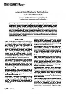
13 Case 3: Rocket engine ignition
Dr.-Ing. Roland Schmehl
Storable propellant upper-stage engine of Ariane 5
•
Hypergolic propellants MMH/N2O4
• • • • • • • • •
Multiple re-ignition in vacuum Regenerative cooling by MMH Multiple point injection Engine dry mass: 1.2 t Total propellant usage: 10 tons Vacuum thrust: 3 tons Tank pressure: 1.8 MPa Chamber pressure: 1.1 Mpa Chamber temperature: 3000 K
Propulsion and Aerothermodynamics Division European Space Agency
Image source: EADS Astrium-ST
14 Rocket engine ignition
Dr.-Ing. Roland Schmehl
Ariane 5 flight 142 anomaly in 2001
•
Observed anomaly: – Pressure peak and subsequent high-frequency combustion instability – Combustion chamber overheats and chamber cooling lines are punctuated – Propellant loss results in lower orbit of payload (ARTEMIS)
•
Objective: – Identify possible reasons for pressure peak using CFD & available data from parallel experimental investigations at ONERA and DLR
Propulsion and Aerothermodynamics Division European Space Agency
15 Rocket engine ignition
Dr.-Ing. Roland Schmehl
Possible causes addressed in failure analysis
– – – – – –
Propellant thermodynamics? Flow dynamics (is pre-flow phase long enough, ...)? Combustion chemistry (pre-ignition reaction products, nitric acid, ...)? Pre-ignition accumulation of propellant (spray deposition, ...)? Dynamic coupling of internal hydraulic circuits and supply lines? Pressure dependence of atomization (pressure-swirl type atomizers)?
Propulsion and Aerothermodynamics Division European Space Agency
16 Rocket engine ignition
Dr.-Ing. Roland Schmehl
CFD analysis of oxidizer preflow phase
Propulsion and Aerothermodynamics Division European Space Agency
17 Rocket engine ignition
Dr.-Ing. Roland Schmehl
Effect of droplet size distribution on flow temperature
Propulsion and Aerothermodynamics Division European Space Agency
18 Dr.-Ing. Roland Schmehl
Rocket engine ignition Oxidizer preflow dynamics
Isosurfaces of liquid volume concentration vc=1%
Propulsion and Aerothermodynamics Division European Space Agency
19 Dr.-Ing. Roland Schmehl
Case 4: ECLSS condensate buffer Flow design optimization
•
Purpose: – Preconditions two-phase flow entering flow separator in Environmental Control and Life Support System (ECLSS) of European Columbus module for ISS
•
Objective: – Flow design optimization to minimize carry-over of liquid
Original design Propulsion and Aerothermodynamics Division European Space Agency
Improved design with anti-sloshing insets
20 ECLSS condensate buffer
Dr.-Ing. Roland Schmehl
Condensate buffer with low liquid phase loading
Propulsion and Aerothermodynamics Division European Space Agency
21 ECLSS condensate buffer
Dr.-Ing. Roland Schmehl
Condensate buffer with high liquid phase loading
Propulsion and Aerothermodynamics Division European Space Agency
22 Dr.-Ing. Roland Schmehl
ECLSS condensate buffer
Condensate buffer single-phase flow Large Eddy Simulation
Propulsion and Aerothermodynamics Division European Space Agency
23 Dr.-Ing. Roland Schmehl
•
Case 5: Airbag deployment
Design objectives – Develop and validate final shape of deployed airbag for In-Position scenarios – Develop and validate shape evolution and interaction with dummy for Out-OfPosition (OOP) scenarios – Support continuous exploration of new airbag concepts and shapes driven by increasingly stringent occupant safety regulations
MADYMO simulation FE model of tube fabric CFD model of internal flow Ambient exterior
31 Future perspectives
Dr.-Ing. Roland Schmehl
Simulation approach for kite aerodynamics
•
Used for support of system design and detail analyses
•
Kite simulation toolbox based on MB dynamics (Adams solver) – Currently developed by ir. Jeroen Breukels
•
FE / UP / CFD simulation using coupling – – – –
Membrane and foam structure represented by Finite-Element (FE) model Inflated chambers represented by Uniform-Pressure (UP) model Exterior flow field represented by CFD model Fluid-Structure algorithms to couple these models
→ Can be done using state-of-the-art airbag deployment solvers (e.g. MADYMO, LSDyna, …), if necessary in combination with dedicated aerodynamics solver (e.g. Fluent, …).
32 Dr.-Ing. Roland Schmehl
Future perspectives Design parameters of kite power system