mechanism with a layered network topology, FlowCode al- lows us to realize the
gains of ... A well-known result from [4] is that coding can be used to increase ...
Paper ID 901699
FLOWCODE: MULTI-SITE DATA EXCHANGE OVER WIRELESS AD-HOC NETWORKS USING NETWORK CODING H. T. Kung, Chit-Kwan Lin, Tsung-Han Lin, Stephen J. Tarsa, Dario Vlah Harvard University Cambridge, MA
ABSTRACT We present FlowCode, a system that exploits network coding at the granularity of traffic flows to facilitate fault-tolerant data exchange in wireless mesh networks. Applications include multi-site data replication in adhoc environments such as mesh networks or wireless data centers. By coupling an operand-driven transmission mechanism with a layered network topology, FlowCode allows us to realize the gains ofnetwork coding in application systems without a global scheduler. We analyze the resulting gains through modeling and simulation and validate our results on an outdoor testbed of 12 wireless devices. Results indicate that in high loss environments, FlowCode provides the most significant gains from improved fault tolerance over redundant paths.
1. INTRODUCTION Network coding in wireless mesh networks using Random Linear Coding has two proposed advantages: increased capacity in the presence of certain traffic flows and improved resilience against lossy links [1] [2] [3]. Our goal is to understand these benefits from a realworld application perspective. To this end, we present FlowCode, a system aimed at maximizing these capacity and fault tolerance gains in data exchange over wireless mesh networks. By coupling a layered network topology with a distributed operand-driven transmission algorithm, FlowCode orchestrates traffic cross-flows to exploit coding opportunities without a global scheduler. A well-known result from [4] is that coding can be used to increase network capacity by reducing the number of transmissions required to exchange data over wireless media. In practice, building a system that can identify and facilitate these desired traffic cross-flows is not straightforward. In one example, COPE [5] extracts gain by buffering and opportunistically gathering information from neighbors about what coding opportunities might exist. Alternatively,
978-1-4244-5239-2/09/$26.00 ©2009 IEEE
I2MIX [6] proposes to perform inter-flow coding by taking advantage of routes that encourage overhearing amongst intermediate nodes. In contrast, our system labels packets to identify flow direction and maximizes coding opportunities by using a layered network topology to balance traffic traveling away from a root layer with taffic moving toward the root layer. When flows intersect, their packets are coded together and broadcast. In the context of wireless mesh networks, network coding also provides rich fault tolerance benefits. First, in the presence of redundant paths spanning multiple collision domains, coding is an efficient way to transmit packets in parallel over multiple paths that decreases total transmission time [7]. Second, coding inside the network at multiple nodes can produce packets that are independently innovative to receivers, allowing links to recover losses from each other. Third, as with many coding schemes, random linear coding defends against the "coupon collector" problem [8] [9]. Recipients are only required to collect a sufficient number of unique packets to recover data, rather than any specific set. To achieve these gains, nodes within the network generate random linear combinations of packets and leave costly decoding operations like Gaussian elimination to end-recipient nodes. FlowCode is designed to realize the gains of network coding in application systems running on wireless mesh networks. In particular, we target multi-site data exchange applications and analyze the capacity and fault tolerance gains from network coding in detail through modeling and simulation. In addition, we implement multi-site data replication in the field using commercial off-the-shelf 802.11 radios on small Mobile Internet Devices (MIDs). In a series of controlled field experiments, FlowCode is able to complete data transfers in high loss situations, where a benchmark uncoded mechanism is unable to complete at all. These results are in line with those previously suggested through simulation [10]. We believe that in high-loss scenarios, the fault tolerance gains identified, modeled, and demonstrated in this work would in general outweigh the
1 of 10
Paper ID 901699
sources to destinations, even if these paths exist for very short periods of time.
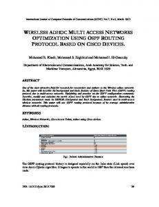
Figure 1: A mesh network of wireless nodes. Nodes A and B are data sources (red) and wish to replicate data to each other. There are three possible paths across the middle links (asterisks) through which data can flow. The numbers at the bottom indicate the layer to which the nodes above belong; the root layer is Layer 4. Blue arrows indicate human-subject walking tours for implementing intermittent links (see Section 7).
capacity gains of network coding, and may have significant implications for wireless data transport systems.
2. SCENARIO Multi-site data replication over ad-hoc wireless mesh networks is a vehicle for illustrating (1) the extent to which network coding gains can be realized in a realworld system and (2) system methodologies that allow us to do so. Data replication is of general interest to many application scenarios. Perhaps the most familiar use is in data centers, where multi-site database replication is an important component of solutions for high availability and reliability. Similarly, for applications in the field, replication of sensor data allows for high data availability across geographic regions and reliability against attacks on even multiple sites. We define the following problem scenario, shown in Figure 1: data sources (nodes A and B) wish to replicate data files as quickly as possible to all the other sources. This particular configuration is a two-site data replication scenario, with A at one site and B at the other. We assume no a priori knowledge of broadcast domains. A system that effectively employs network coding in such a scenario must take into account the following design considerations: Fault tolerance. Ephemeral environmental effects such as fading, interference, and path loss serve to make link quality in wireless mesh networks variable, unpredictable, and often poor. These challenges are magnified when the design space includes mobile nodes. Ideally, a fault tolerant system designed for multi-site data replication should automatically exploit alternative paths through which data can flow from
Coding opportunities. Capacity gain in wireless networks can be realized when data flowing in opposite directions intersect at an intermediate node, giving rise to coding opportunities. Thus, a system must be able to distinguish the direction of data flows at intermediate nodes in order to recognize and exploit coding opportunities. More significantly, a system should strive to encourage these coding opportunities by managing traffic flows and network topology. Coding schedule. Once coding opportunities are possible, the system must ensure that they are actually scheduled to occur. Consider node H in Figure 1, where packets from nodes C, D, and K converge. To achieve maximal capacity gain from network coding, a transmission schedule should be instituted such that one packet each from C and D, and two from K are available to be coded at H when H is scheduled to send. Herein, we use the term coding schedule to avoid confusion with the common definition of "transmission schedule" used in the context of medium access control. In this paper we make a simplifying assumption that random linear coding will always generate linearly independent combinations of input data. In practice, there is a small probability that this assumption will not hold, which may require a minor global adjustment to our results. Results in [3] show how quickly this probability can be decreased by limiting the number of coefficients chosen relative to the size of the finite field.
3. THE FLOWCODE SYSTEM Our system satisfies the above three design criteria with two complementary mechanisms: a layered topology and operand-driven transmission. Layered topology. In order to distinguish the direction of data flows, we assign each node to a layer. For example, a layering scheme for the topology in Figure 1 is shown at the bottom of the diagram. Layer assignments provide an ordering of nodes that emanates from sources, and converges at a root layer. Nodes in the root layer must distinguish from which region arriving flows originate (for two-site data replication, regions equate to left or right). Here, designating Layer 4 as the root layer is arbitrary and choosing J, K, and L to be the root layer would be equivalent; this generalizes to other symmetric topologies. Based on the layered topology, flow direction can be determined using the root layer as a reference. Upstream
20fIO
Paper ID 901699
flows are defined as flowing toward the root layer, while downstream flows are those moving away. When upstream and downstream flows converge at a node, a coding opportunity is possible. In Section 6, we discuss dynamic layer assignment for multi-site scenarios.
Operand-driven transmission. We achieve a coding schedule by triggering nodes to code and transmit whenever the necessary data (operands) arrive at the node. The rules for this are relatively simple: (1) Internal nodes immediately code and transmit packets flowing upstream, even if there is no downstream flow with which to code. In contrast, packets traveling downstream are buffered and encoded with the next packet flowing upstream. (2) Root nodes should attempt to encode data flowing in opposite directions within a short timeout period T, after which they send regardless of coding opportunity. We show in Section 4 that this operand-driven transmission scheme can automatically achieve a globally-optimal coding schedule. Employing these mechanisms in tandem allows multiple redundant paths to be used automatically, providing fault tolerance without an additional specialized scheduling mechanism. Due to broadcast advantage, multiple nodes can receive transmissions from lower layers and operate independently based on the operand-driven rules. The result is that innovative packets flow along multiple paths in parallel. Later, we demonstrate that network coding's fault tolerance gain can be substantially larger than capacity gain for such systems. We now have the context within which to introduce the FlowCode algorithm (Algorithm 1). The overall goal of the algorithm is to maximize the innovativeness of each broadcast without starving upstream nodes by waiting excessively. Nodes listen promiscuously and send upon receiving data from a lower layer.
Algorithm 1 The FlowCode Algorithm 1: upCount f - 0 2: downCount f - 0 3: leftCount f - 0 4: rightCount f - 0 5: procedure ONREcElvE(packet) 6: if ISSOURCELAYER(myI D) then 7: STOREEQUATloN(packet) 8: else if IsINTERNALLAYER(myId) then 9: STOREEQUATloN(packet) 10: if IsGoINGDOwN(packet) then 11: downCount f - downCount+ 1 12: else if IsGoINGUp(packet) then
13: 14: 15: 16: 17: 18:
19: 20:
21: 22:
upCount
f-
upCount + 1
TRIGGERSEND end if else if IsROOTLAYER(myld) then STOREEQUATloN(packet)
if IsFROMLEFT(packet) then
leftCount f - leftCount + 1 else if IsFROMRIGHT(packet) then rightCount f - rightCount + 1 end if
23: WaitT 24: TRIGGERSEND 25: end if 26: end procedure 27: procedure TRIGGERSEND 28: if ISSOURCELAYER(myI D) then 29: Send 1 RLC of current generation, label it "up" 30: else if IsINTERNALLAYER(myId) then 31: whileupCount> Odo 32: Send 1 RLC of stored packets, label it "up/down"
33: 34: 35: 36: 37: 38:
39: 40: 41: 42:
downCount f - min(downCount - 1,0) upCount f - min(upCount - 1,0) end while else if IsROOTLAYER(myId) then while leftCount > 0 or rightCount > 0 do Send 1 RLC of stored packets, label it "down"
leftCount f - min(leftCount - 1,0) rightCount f - min(rightCount - 1,0) end while
end if 43: end procedure
4. ANALYSIS In this section, we analyze system performance. First, we show how a layered topology and an operanddriven transmission mechanism achieve capacity gain using network coding. Second, we show that operand-driven transmission can produce the optimal schedule for certain topologies. Finally we discuss in detail the fault tolerance gains that these protocols yield for a mesh network with multiple redundant paths.
4.1. Capacity Gain As in the classic Alice-Bob example [4], our system achieves capacity gain by coding together packets traveling
in opposite directions. To illustrate, consider the toy wireless network in Figure 2. The four leaves seek to exchange data over a wireless mesh arranged in a tree. Dotted circles denote shared broadcast domains. Within these circles, nodes can overhear each other and will interfere if they transmit at the same time. At the i-th step in a FlowCode data exchange, senders A and B code over a generation, producing packets [a]i and [b]i. These packets are sent up the tree to node E. In the steady state, downstream packet [cd]j sent from a higher layer has already arrived and has been stored at node E, waiting for operands. At this point, E codes all packets that it holds and broadcasts two linear combinations
30fl0
PaperID 901699
[[abli[ed]j] . Thus, data originally encoded in [ali and [b]i are propagated up the tree, while [ej] and [d j] are delivered
downstream to A and B, where they are extracted via decoding. Capacity gain is realized since four pieces of information are forwarded in only two transmissions by E. This type of capacity gain is well-known and has previously been studied in various topologies [5]. The basic limitation is that the maximum reduction in the number of transmissions due to network coding is equal to the minimum number of pieces of data already possessed by any given receiver. In the case of data exchange, where two nodes seek to exchange n disjoint pieces of data via an intermediary, coding requires only n transmissions by the intermediary, compared to 2n in uncoded. This leads to the observation that network coding capacity gain is bounded by a factor of two. 4.2. Scheduling
The motivation behind operand-driven transmission is to exploit network coding without a global schedule. Using the toy example in Figure 2, we present an optimal global schedule with maximum capacity gain and show that operand-driven transmission yields an identical schedule automatically. Figure 3 shows the optimal steady-state coding schedule for one round of data exchange over the topology in Figure 2. Leaves are assigned one time slot each, but because A and C (similarly, B and D) are not in the same collision domain, their four slots can be collapsed into two. Internal and root nodes such as E must send once for every leaf transmission to ensure that destination nodes can eventually decode. As a result, each internal and root node must occupy two time slots. This schedule gives the minimum number of transmissions required to complete the data exchange. Note that E exhibits a two-fold gain in throughput over an optimal schedule without coding. We next compare with the schedule produced by FlowCode. Consider the data flows passing through node E . Upon receiving downstream packet [edlj, node E stores it until an operand going upstream arrives. Since we are considering the steady state, we can assume E always possesses at least one operand [ed] j going downstream. Next, suppose A and B send operands [ali and [b] i upstream through E . Since we rely on CSMA to provide fair share, [al i and [b] i may arrive at E in any order, resulting in two possible cases: 1) the symmetric case, where both [al i and [b]i arrive at E before being coded and sent upstream. Two random linear combinations [[ab]ded]j] are sent, permitting decoding at the destination.
2) the asymmetric case, where (without loss of generality) [al i arrives at E first. E will then send [[a]ded] j] . When [b] i arrives later, E will subsequently send [[ab]ded] j] . These two equations are well-constrained and can be solved by any recipient already possessing any two of the four operands. In both situations, two transmissions from E will propagate enough information for eventual the recipients to decode. Extending this trace to cover the whole topology results in a schedule identical to Figure 3. Though proving that operand-driven transmission gives the optimal schedule in all cases is more complicated, we use this result as sufficient motivation to apply it to mesh topologies. In practice, CSMA under full channel utilization may not attain the optimal schedule. To remedy this in simulation and in the field, we rate limit source nodes. This allows the optimal schedule to be achieved by permitting properly balanced node duty cycles across the topology. (See further discussion on source rate limiting in Section 7.2.) 4.3. Fault Tolerance Gain In this section we model the fault tolerance gains due to coding across multiple links. Network coding is compared with a simple uncoded mechanism where the sender chooses packets uniformly at random to send, transmitting blindly until the receiver assembles the complete set of data. We first present a model for sending data over a single lossy link and analyze overall completion time, determined by the the number of source tranmissions required to successfully deliver n packets. Single link model. Figure 4a shows node A transmitting data to node B over an unreliable link with packet loss probability p. For our random uncoded protocol, the expected value E[T] of the number of transmissions T satisfies E[T] = (1~p) Hn , where n is the number of unique packets to be sent, and H n is the n-th Harmonic number.
I
,
;
I
\
)\ I I I \
I
\
-------
--
....... ,
, __
.....
,
l aye r
3
\
\ I
."
,,
.-.-
.... I
2
....
_--"
....
_--,
Figure 2: A toy network in which nodes A, B, C, and D seek to exchange data. Broadcast domains are marked by dashed lines.
4oflO
Paper ID 901699
Time Slot Sende r
Data flow
1
2
A,e
B,D
4
3
[a];->B,E [bl;->A,E [c];->D,F [dl;->C,F
5
E
6
7
8
A,e
G
F
10
9
B,D
[[abUcdl;l [a];+,->B,E ->E,F [cL+c >D,F
[[abl;[cdld [[cdl;[a b]kl ->A,B,G ->C,D,G
11 12
13
14
E
F
...
[[fgUab];+d [[abWg];+,] ->C,D,G ->A,B,G
[b];+,->A,E [d];+,->C,F
Figure 3: The optimal global schedule for nodes A , B, C, D to exchange a coded packet in the steady-state, based on the topology and broadcast domains in Figure 2. A round of data exchange takes 8 time slots . Operand-driven transmission produces an identical schedule.
c
-----0 (a) Single Link Model
D
redundant links satisfies:
~>
•
k -
E[Tuncoded] _ E[Tcoded] -
B
F
(b) Multi Link Model
Figure 4: (a) A simple model in which a node transmits data over a single lossy link with packet loss probability p. (b) A model in which nodes transmit data over a wireless mesh with k redundant links, each with loss probability p.
. (k(l - p) H 1 H) (1 _ pk) n, (1 _ pk) n
mm
(1)
We call the right-hand expression of Eq. (1) the modeled gain. We can also express E[Tcoded] in terms of the probability that a given number of transmissions is required:
E[T] =
00
L i x Pr(T = i) ,
(2)
i=n
where
H n arises from the fact that as more packets are collected by the receiver, the set of outstanding packets becomes more specific and harder to satisfy [11]. This factor is derived from the "coupon collector's" problem, and grows proportionally to log n. Multiple link model. In wireless mesh networks, the presence of parallel links offers an opportunity to create redundant paths. Here, we model the gains from coding over such paths . Figure 4b shows node A transmitting to node B over a mesh with k redundant paths. Each path experiences independent losses with probability p. For simplicity, we assume only the middle dashed links are lossy and that other links are perfect (p = 0). In the uncoded scenario, k paths provide k chances to successfully transmit a packet. The probability of transmission failure across the entire system is reduced from p to pk. The expected number of transmissions in the random uncoded protocol becomes E[Tuncoded] = (l ~pk ) Hs : With network coding, there is an additional gain due to redundant paths. Since coding occurs independently within a network of lossy links, each coded packet could be innovative to the receiver. For example, when packets are coded with previously sent packets at different points inside the network, the resulting coded packets may each contain additional information not yet received at node B . Thus, it is possible that k links can deliver k innovative packets simultaneously, meaning E[Tcoded] at best can be reduced by a factor of k. Since E[Tcoded] 2: n, we have
E[Tcoded] = max(n/k(l - p), n). The fault tolerance gain of network coding for k
Pr(T
= n) = 1 -
Pr(T > n),
+ 1, ..., i + 1) = Pr(T > i)
and fori = n , n
Pr(T = with
Pr(T> i) =
- Pr(T > i
+ 1),
L (".Ok) p(ik- j )(I _ p)j
n -l
j=O
J
In this last expression, Pr(T > i) is the probability that destination node B receives fewer than n innovative packets after i transmissions from A. We can numerically compute E[T] based on Eq. (2). Using this E[T], we can compute E[Tuncoded]/E[Tcoded], which we call the analytical gain. Figure 5 plots the modeled and analytical gains from network coding over k links for the case when p = 0.8 and n = 20. This plot shows that the modeled gain provides an upper bound for the analytical gain, and the bound is fairly tight for k < 4 and k > 6. The analytical gain in Figure 5 exhibits an optimal value of k for a given system, corresponding to the point where the network is capable of delivering, on average, exactly one packet to the destination per source transmission. Networks with smaller capacity would require additional source transmissions, while networks with larger capacity would incur unnecessary packet transmissions at intermediate nodes . Thus this optimal value for k can be derived using network capacity [12] . In our model of Figure 4, k is optimal at 1/(1 - p) (with k = 5 for the toy example with p = 0.8), and is confirmed by results from our network simulator (Section 5.2).
50f1O
PaperID 901699 7
u
"0
0
o
E w
""
6 5.5
U
"0
0
o
5
c
:J
E w
"
c
·ro
o
• • •
6.5
•• • • k(1-P)Hn/(1- pk) •• •
•
••
completion-time not explained by a reduction in source transmissions. Each source has 20 data blocks to send, and the number of middle links is varied from 1 to 20. Loss probabilities p E {0.50, 0.80 , 0.95} are simulated. Each simulation is run for 50 trials .
•
4.5 4
5.2. Results
3.5 3
2
4
6
8
10
12
k = Number of Middle Links
Figure 5: Analytical gain for network coding over a varying number k of middle links (p = 0.8, n = 20). Our modeled gain (minimum of the dashed green and blue curves) is an upper bound for the analytical gain (red solid curve). Note that when k is sufficiently large (e.g., k > 3), not every packet delivered is innovative. Therefore the analytical gain gradually deviates from our modeled gain that assumes every packet received is innovative (green dashed curve). When k is larger than another higher threshold (e.g., k > 7), the analytical gain converges to the optimal state (blue dashed curve) since in this situation the source need not make redundant transmissions. Observe that overall the fault tolerance gain is 3.5-5X.
5. SIMULATION 5.1. Setup In order to demonstrate capacity and fault tolerance gains in a network with a variable number of lossy paths, we built a network simulator. FlowCode is implemented and packet-level behavior with actual encoding and decoding is modeled using random linear coding. A topology with two data sources is used (depicted in Figure 1). Links between Layers 3 and 4 drop packets uniformly at random with a specified loss probability p, while all other links in the network are 100% reliable. Increasing the number of source-to-destination paths is done by adding nodes to Layers 3 and 4 and connecting them with a lossy link . We compare FlowCode with the random uncoded protocol described in Section 4.3. Two metrics are tracked: (1) the number of source transmissions before the data exchange completes, taken as a maximum over both sources and (2) the sum of transmissions on links between nodes assigned to Layers 2, 3, and 4. This first metric tracks fault tolerance gain, as it measures the number of redundant packets sources must send to complete the transfer. The second metric corresponds to the number of transmissions in the largest collision domain in the network, and is a surrogate for overall completion time . We infer gains from capacity increase by looking at improvements in
Figure 6 shows results for p = 0.80. Both coded and uncoded strategies require fewer source transmissions as the number of middle links increases, driven by the decreased probability of delivery failure across the system. Optimal performance (no redundant packets are required), is achieved by FlowCode with few middle links (5 for p = 0.80), while uncoded transmission requires no fewer than 80 transmissions even with 20 links . The trend holds across the other simulated loss rates : for p = 0.50 the optimum is achieved with k = 2 and for p = 0.95, with k = 19. The second metric, the total number of transmissions at nodes in the largest collision domain, is shown in Figure 7 for p = 0.80. Taken as an indicator of total completion time, uncoded transmission yields higher completion time in all cases. Also , by this metric, performance degrades for k > 4, corresponding to the point at which a sufficient number of paths exist for data to be transmitted with minimal transmissions. Additional links create channel contention without providing additional gain . The results are similar for p = 0.5 and p = 0.95. Figure 8 plots overall capacity and fault tolerance gains realized by network coding. In our simulated scenarios, capacity gain is well below its theoretical bound of 2X. In contrast, fault tolerance benefits yield a 3- to 6-fold increase in performance. The combined gain from coding results in a 5- to 7-fold increase in performance.
6. FLOWCODE DYNAMICS Due primarily to space constraints, FlowCode dynamics are the subject of an upcoming follow-on paper. Below we introduce issues and briefly discuss possible solutions.
Layer assignment and multi site data replication. In an arbitrary mesh, FlowCode uses layers to exploit coding opportunities. Since some paths exist intermittently, relying on link quality to assign layers is inadequate. Instead, we use geographic location data, which can be obtained from GPS chips or by using range-based localization methods designed to cope with flaky links, like SISR[13] . Assigning layers based on location can be approached with global knowledge of node locations and also with
60fIO
PaperID 901699 220 ...----.--..----.----...--........---......-........---......--.---, Uncoded Network Coding Optimum
200 180
multi-site replication scenarios in order for FlowCode to execute properly.
. ..
160 140 120 100 80 60
~- ,
:~
.......::::*:::,:::::,t.::::,1II,
0 ' - ---'--
o
2
n_n""'_''', .._...~.._..~.._...,...._o+
' - ---'----'' - -..........- - - ' ' - -..........- - - ' ' - -......... ---'
4
6
8
10
12
14
16
18
20
Numbe r of Middle Links
Figure 6: Simulation measuring the number of source transmissions under p = 0.8. Network coding can recover packet losses more easily than the uncoded approach, and converges to the optimum quickly. c O ro E
5000
0
4500
0
c 0
~
4000
o
3500
'e>ro"
3000
(5
Ui
-..J
'" = "'= c: '" 0
"in
'" E c '" l"
Uncode d Netwo rk Coding .......
Dynamic layer adaptation With the inclusion of mobile nodes and the possibility of varying conditions such as interference, the initial geography-based layering may need to be adjusted dynamically. We propose an algorithm whereby each node periodically updates its layer assignment in order to maximize the number of packets that it codes and forwards. Dynamic layer adaptation can be based on a bookkeeping mechanism that tracks the possible layer assignments that a given node may assume. This table requires two columns, one to tally operands moving upstream, and another for packets moving downstream. Entries are kept for possible layer assignments that a given node may assume, and packets are evaluated and tallied against these possible assignments. Nodes periodically update their layer assignment by choosing the layer that maximizes throughput.
2500
7. FIELD EXPERIMENTS
2000 1500 1000
f-
500
~ f-
0
.......................................................................... 0
4
6
8
10
12
14
16
18
20
Number of Middle Link s
Figure 7: Simulation measuring the total number of transmissions in the largest collision domain for the network of Figure 1, under p = 0.8. The total number of transmissions is an approximation of the best achievable completion time under CSMA. The gain of network coding shown is a combination of both capacity and fault tolerance gains . Error bars denote standard deviations.
limited local knowledge. Given global knowledge, layers are established by recursively subdividing the network graph and assigning nodes to layers based on their proximity to the dividing line. Given local knowlege, we can use a greedy algorithm for layering similar to GPSR used in geographic routing [14]. Nodes require only knowledge of their immediate neighborhood and their intended destination. Similar to GPSR, this method must route data further from a destination to circumvent a void. Layer assignment gives rise to several interesting issues. A global method incurs more overhead relative to a local method in order to disseminate node positions. However, for a local method, it is a challenge to place the root layer in a balanced position. In addition, rapid adaptation of layering is required to accomodate bursty traffic. Finally, assigning layers for an abritrary number of regions, with a root layer at transition points between these regions, is required in
We implemented and deployed FlowCode on an outdoor testbed of 12 wireless nodes. We also implemented the uncoded multi-site data replication protocol as described in Section 5 as a point of comparison. Each node in our testbed is a Mobile Internet Device (MID), shown in the inset of Figure 10, with an x86compatible Intel Atom 800MHz processor, 512MB RAM and a 4GB flash disk, running Linux. The radio on the MID is a Marvel SD8686 802.11b/g internal SDIO device with a single internal antenna. For all our experiments, the nodes were placed in ad-hoc mode and set at the l Mbps modulation. 7.1. Topology Construction For proper performance measurement, we need to conduct tests under a wide range of faulty conditions. Producing this kind of behavior in a consistent manner in outdoor deployments of ad-hoc topologies as in Figure 1 can be difficult. Moreover, in our scenario, we have the added requirement that link outages and loss must be highly variable. As a result, we eschew the labor-intensive step of tuning node locations to satisfy these constraints. Instead, by placing nodes on the ground 35ft apart, we exploit radio ground effects to start from a configuration where nodes cannot talk directly to each other at all. We induce communication in a controlled but irregular fashion by having a person walk between the nodes to reflect the radio signals. The randomness of these reflections, due to the
70fIO
Paper ID 901699
'8 '7
.....-
'6
p=O.5 p=O.8 .-.-. p=O.95 "" . ..,,
"
'4
1.3
"
1.1
,
_
",.",•• ,.,.,,,
.
,,",, ,.,•.•,.',.,.,.,.•
oL-~,~ 4 ~6~8~'~ 0 -
,'=,""~ 14----:': ' 6~18,.---"O
Number of Middle Links
(a) Capaci ty Gai n
3 O L
~ '~ 4 ----':"6~8~'.,.... 0-
,'=,""~ 14~ ' 6~18,.---"O
3
L-~~~~~~~~~,----.J
o
2
4
Numbe r of Middle Links
6
8
10
12
14
16
18
20
Number of Middle Links
(b) Fault Tolera nce Ga in
(c) Over all Ga in
Figure 8: Simulation measuring network coding gain under different link loss probabilities. The overall gain is comprised of capacity and fault tolerance gain. Capacity gain is less in high-loss scenarios due to asymmetric traffic flows, and is at most 2X. Fault tolerance gain is more prominent.
irregular motion and surface of a human body, results in variable and lossy links between nodes. The blue arrows in Figure 1 indicate the walking tour paths that were simultaneously taken by three people in each experiment. Note that the radiating energy that these people receive is no higher than that of a typical office or home environment with 802.11 access points. To illustrate that such a technique can indeed satisfy our needs, we performed a simple calibration experiment. First, we placed a transmitter on the ground 35ft away from the receiver and verified that the packet delivery rate over 30 seconds was zero. Next, we marked a 45ft x 65ft grid around the nodes as shown in Figure 9, with 5ft separation between each successive grid point. To calibrate, a human subject stood at a grid point to act as a reflector and the packet delivery rate was measured between the transmitter and receiver. This was repeated for every grid point shown. The heat map in Figure 9 shows the resulting packet delivery rates induced by a human subject standing at each grid point. Notice that delivery is highest when standing around the transmitter. A human subject standing on the line between the transmitter to receiver induces packet delivery as well, albeit at a reduced rate due to signal blockage.
7 0.8
6
5
0.6
4 0.4
3 2
0.2
o 1
2
3
4
5
6
7
8
9
10 11 12 13
Figure 9: Outdoor calibration experiment. Transmitter (TX) and receiver (RX) nodes are placed 35ft apart on the ground and grid points are 5ft apart. The packet delivery rate when a person stands at a grid point is shown by the heat map color of the corresponding grid cell. Note that the packet delivery rate is highest when a person stands near the transmitter.
7.2. Experiment Setup We arranged 12 nodes on a flat outdoor field in three topologies which we term "3-Path", "2-Path" and "I-Path". The 3-Path topology is exactly as shown in Figure 1. The 2Path topology has the bottom middle link (denoted with an asterisk) removed. The l-Path link additionally has the top middle link removed (also denoted with an asterisk). Across these three topologies, we executed both coded (FlowCode ) and uncoded multi-site data replication, while three people walked amongst the nodes, as previously described. Figure 12 shows the packet delivery rates for each link in our test topology, as calculated over an entire
Figure 10: Photograph of our outdoor testbed of 12 wireless nodes, deployed in the physical topology shown in Figure 1. The inset shows one of the MID nodes in our testbed.
experiment (approximately 10 minutes) . In general, links are asymmetric and link quality is quite poor (packet loss rate J.1 = 0.75, a = 0.73). With minimal location tuning, we created a topology that resembles the desired topology in
80flO
Paper ID 901699 900
Coded t = Uncoded
==
800 700 U>
Q>
600
E i= c
500
~
400
E u
300
0
Q. 0
200 100
a
1-Path
2-Pa th
3-Path
Topology
Figure 11: Field experiment results on completion times of coded (FlowCode) and uncoded data replication across three topologies. The solid blue stacked bars in l-Path and 2-Path topologies indicate uncoded runs that did not complete even in the times shown. In the 3-Path topology, coded experiences 4X shorter completion time due to the fault tolerance gain from FlowCode.
Figure 1 with two sources at each site. In our field experiments, the performance metric tracked is replication completion time across all source nodes. Each of the source nodes had 150KB of data to replicate to the other three and was rate limited to ensure that wireless medium scheduling was not a bottleneck in throughput. Nodes in our topology have roughly four contending neighbors (see Figure 12), meaning at IMbps modulation, source nodes must be rate limited to rv 150kbps (l/6th the bandwidth) in order to allow medium access without contention in the interior of the network. Figure 11 shows the results of these field experiments. With the l-Path topology, the single bottleneck link between the sources causes huge completion times: coded (FlowCode) finishes in 620s whereas uncoded remained incomplete after 697s (a single node held up everyone else with only 60% complete data). By adding a second redundant link, the 2-Path topology already showcases the advantage of FlowCode-the coded completion time drops to 21Os, whereas uncoded still is unable to complete even after 794s (again, a single node with only 96% complete data held up the rest). With the third redundant link added in the 3-Path topology, the completion time for coded is driven even lower to 154s and, finally, uncoded is able to complete in 650s. This represents a 4X performance gain of coded over uncoded, which closely corresponds to the gains in our simulation for p = 0.80. Finally, it bears mentioning that the field experiments used the lowest, and most reliable 802.11b modulation of 1Mbps. It is possible that high-modulation packets, which propagate faster, may take better advantage of momentary indirect links. This tradeoff is a priority for future work.
Figure 12: Topology and packet delivery rates (PDR) between outdoor nodes as measured during the field experiment. Each link between node m and n (m < n) is labeled with Pl1P2, where P, is the PDR from m to nand P2 is the PDR from n to m . While the topology does not exactly match the one depicted in Figure 1, the similarity is high. Links are highly asymmetric and quite lossy (packet loss rate j..t = 0.75 , (J = 0.73). Good links with > 50% PDR are in blue.
8. RELATED WORK
There is a significant body of literature on network coding beginning from the seminal proposals and proofs of viability in [2] [3] [4]. Drawing from this work, we implement coding using methods for Random Linear Coding as described in [1]. Though many applications have been proposed, such as P2P file transfer [9] and even reliable data disemmination over wireless ad-hoc networks [10], these results have been mostly confined to simulation. A notable exception is COPE [5], which examines capacity gain from network coding in a wireless mesh. The importance of opportunistic listening to realize capacity gain is further discussed in [15]. In contrast to the COPE system, which focuses on the feasibility of theoretical capacity gains, in this paper we choose to focus on system design to realize the benefits of network coding in applications. Using multi-site data exchange as a vehicle, we examine coding gains that impact bottom line application performance. FlowCode allows us to derive gain from both inter-flow coding and the intra-flow coding made possible by coding over multiple packets in a generation, similar to a system proposed in I2MIX [6] Other application-based network coding studies include [16], which concerns content distribution in multihop/mobile networks, and [17], which employs a cooperative content downloading application using mobile nodes.
90flO
Paper ID 901699
9. CONCLUSION In this work, we have presented FlowCode, a system for leveraging network coding to improve fault-tolerance and throughput for data exchange over ad-hoc wireless mesh networks. Concentrating on a well-defined application scenario, we model and simulate the data exchange application, as well as implement a system for field experimentation. We demonstrate that FlowCode's coupled mechanisms of coding based on a layered topology with operanddriven transmission realize substantial performance gains, especially in high loss scenarios. We attribute performance improvements to the ability of network coding to take advantage of multiple redundant paths to deliver packets with greater reliability and efficiency. While nodes of the system change their number and positions in the field, the same FlowCode code can still be used without change. The ease with which FlowCode can realize fault tolerance gain combined with the substantial resulting performance increase constitutes an important step in applying network coding to wireless mesh networks. Future work will be driven by further experimentation, e.g., extending this application to highly mobile environments. Building off previous work on UAV based communication networks [18], we plan to examine system issues that arise in networks comprised of both airborne and ground-based clusters. Through practical field experiments, we hope to highlight and address system implementation issues that must be considered if network coding is to be deployed widely in real-world applications.
ACKNOWLEDGEMENTS This material is based on research sponsored by Air Force Research Laboratory under agreement numbers FA875008-1-0220 and FA8750-09-2-0180. The U.S. Government is authorized to reproduce and distribute reprints for Governmental purposes notwithstanding any copyright notation thereon. The views and conclusions contained herein are those of the authors and should not be interpreted as necessarily representing the official policies or endorsements, either expressed or implied, of Air Force Research Laboratory or the U.S. Government.
[4] Y Wu, P. Chou, and S. Kung, "Information exchange in wireless networks with network coding and physical-layer broadcast," in CISS, 2005. [5] S. Katti, H. Rahul, W. Hu, D. Katabi, M. M6dard, and J. Crowcroft, "XORs in the air: practical wireless network coding," IEEE/ACM Trans. on Netw., vol. 16, no. 3, pp. 497-510,2008. [6] C. Qin, Y. Xian, C. Gray, N. Santhapuri, and S. Nelakuditi, "I 2mix: Integration of intra-flow and inter-flow wireless network coding," in SECON, 2008. [7] Y Zhu, B. Li, and J. Guo, "Multicast with network coding in application-layer overlay networks," IEEE 1. Sel. Areas Commun., vol. 22, no. 1, pp. 107-120,2004. [8] J. Byers, M. Luby, M. Mitzenmacher, and A. Rege, "A digital fountain approach to reliable distribution of bulk data," ACM SIGCOMM Computer Communication Review, vol. 28,no.4,pp. 56-67, 1998. [9] C. Gkantsidis and P. Rodriguez, "Network coding for large scale content distribution," in Proc. IEEE INFOCOM, 2005. [10] J. Park, M. Gerla, D. Lun, Y. Yi, and M. Medard, "Codecast: a network-coding-based ad hoc multicast protocol," IEEE Wireless Commun., 2006. [11] M. Mitzenmacher and E. Upfal, Probability and computing: Randomized algorithms and probabilistic analysis. Cambridge University Press, 2005. [12] D. Lun, M. Medard, R. Koetter, and M. Effros, "On coding for reliable communication over packet networks," Physical Communication, vol. 1, no. 1, pp. 3-20, 2008. [13] H. T. Kung, C. K. Lin, T. H. Lin, and D. Vlah, "Localization with Snap-Inducing Shaped Residuals (SISR): Coping with Errors in Measurement," in MobiCom, 2009. [14] B. Karp and H. T. Kung, "GPSR: greedy perimeter stateless routing for wireless networks," in MobiCom, 2000. [15] S. Chachulski, M. Jennings, S. Katti, and D. Katabi, "Trading structure for randomness in wireless opportunistic routing," in SIGCOMM, 2007. [16] C. M. Cheng, H. T. Kung, C. K. Lin, C. Y. Su, and D. Vlah, "Rainbow: A wireless medium access control using network coding for multi-hop content distribution," in IEEE MILCOM, 2008. [17] M. Pedersen, F. Fitzek, and T. Larsen, "Implementation and Performance Evaluation of Network Coding for Cooperative Mobile Devices," in IEEE ICC Workshops, 2008. [18] C. M. Cheng, P. H. Hsiao, H. T. Kung, and D. Vlah, "Maximizing Throughput of UAV-Relaying Networks with the Load-Carry-and-Deliver Paradigm," in IEEE WCNC, 2007.
REFERENCES [1] P. Chou, Y. Wu, and K. Jain, "Practical network coding," in Proc. Ann. Allerton Conf., 2003. [2] R. Ahlswede, N. Cai, S. Li, and R. Yeung, "Network information flow," IEEE Trans. InJ. Theory, 2000. [3] T. Ho, M. Medard, R. Koetter, D. Karger, M. Effros, J. Shi, and B. Leong, "A random linear network coding approach to multicast," IEEE Trans. Inf. Theory, 2006.
10 of 10