Fluent-Based Animation: Exploiting the Relation between. Goals and Scenarios for ... Requirements engineers must not only elicit and document scenarios and ...
Fluent-Based Animation: Exploiting the Relation between Goals and Scenarios for Requirements Validation Sebastian Uchitel, Robert Chatley, Jeff Kramer, Jeff Magee1 Department of Computing, Imperial College London [rbc, jk, su2, jnm]@doc.ic.ac.uk Abstract Scenarios and goals are effective and popular techniques for requirements definition. Validation is essential in order to ensure that they represent what stakeholders actually want. Rather than validating scenarios and goals separately, possibly driving the elaboration of one through the validation of the other, this paper focuses on exploiting the relation between goals and scenarios. The aim is to provide effective graphical animations as a means of validating both. Goals are objectives that a system is to meet. They are elaborated into a structure that decomposes declarative goals into goals that can be formulated in terms of events that can be controlled or monitored by the system. Scenarios are operational examples of system usage. The relation between scenarios and goals is established by means of fluents that describe how events of the operational description change the state of the basic propositions from which goals are expressed. Graphical animations are specified in terms of fluents and driven by a behaviour model synthesised from the operational scenarios.
1. Introduction Scenario-based notations such as Message Sequence Charts (MSCs) [9] describe how components, the environment and users interact in order to provide system level functionality. Their simplicity and intuitive graphical representation facilitate stakeholder involvement and make them popular for documenting intended system behaviour. However, scenarios are operational descriptions that leave the required properties of the intended system implicit. Scenarios provide a common ground on which goals can be elicited, discussed, and elaborated, but are not requirements in their own right. 1
Goals [11] focus on the objectives of the systems to be constructed. They are declarative statements and as such complement the operational nature of scenarios. Goals are refined into sub-goals that can be operationalised and assigned to specific components. Hence, goals can serve as a framework for eliciting and elaborating operational descriptions of the required system. validation
goal elaboration
scenario elaboration
object/operation capture goal operationalization responsability assignment
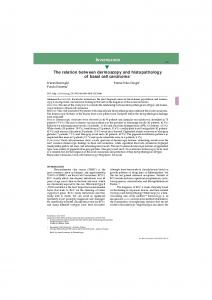
Figure 1 : Interweaving goal-based and scenariobased RE. (Dashed elements taken from [12]). There has been extensive research on the relationship between scenarios and goals, focusing mainly on how one can aid the elaboration of the other. Dotted elements in Figure 1 depict how goal-based and scenario-based RE can be integrated according to van Lamsveerde [12]. All arrows depict data dependencies. Scenarios may prompt the elicitation of underlying goals or be used for goal inference (Figure 1, right-toleft arrow). They can provide examples of how goals can be realised or be witnesses of violations of these goals (Figure 1, left-to-right arrow). Goals may drive the elaboration of new scenarios (Figure 1, left-to-right arrow). However, less attention has been given to how scenarios and goals can be used together to facilitate requirements elicitation, elaboration and validation. In this paper we focus on validation. Validation is a key requirements activity. Requirements engineers must not only elicit and document scenarios and goals, but also validate that
Partially supported by STATUS ESPIRIT (IST-2001-32298) and EPSRC READS GR/S03270/01
these are indeed what stakeholders want [19]. Animation is an effective validation technique, and we show that combining goals with scenarios can result in effective animations that not only support scenario and goal validation, but can also prompt their elaboration. In its simplest form, animation means allowing stakeholders to step through sequences of events dictated by some behaviour model. More sophisticated animations allow stakeholders to visualise some aspect of the system state as they step through the alternative events. However, this is not straightforward to implement if behaviour has been described in the form of scenarios, where the notion of state is implicit. Which system states should be inferred from what are essentially sequences of events? One possibility could be to assume that each event in the scenario leads to a new system state. However, this is too naïve. To present a meaningful animation to a stakeholder, it is not the system state that is relevant but abstractions of it that relate to the concerns of the stakeholder participating in the animation. Goals can be the source for establishing a meaningful partition of system state, because they capture the reasons why the system behaves as described in the scenarios. We believe that animations of system behaviour should be driven by scenarios and displayed from the perspective of the stakeholder participating in the animation and in a way that relates to the stakeholder’s goals. For example, the intermediate states that the system may go through while performing user authentication could be considered irrelevant from the perspective of a user accessing email on a web-based email client. However, given a privacy goal on email access, partitioning the system state space into those where the user has been authenticated and logged on, from those in which authentication has failed, is very relevant. To perform such animations, a relation between scenarios and goals must be established. We build on van Lamsveerde's approach, in which goals are successively AND-OR refined (Figure 1, left circle arrow) into requisites. Requisites are "goals that can be formulated in terms of states controllable by some individual agent". Controllable state refers to states that are entered and exited on events that are controlled or monitored by the agent. However, the goals we use to relate to operational scenarios need not be requisites. We use fluent linear temporal logic (FLTL) formulas [3] to express goals that can be formulated in terms of states controllable by the software system. These FLTL formulas have as basic elements fluents, which are central to establishing the relation between goals and scenarios.
Fluents are abstractions of system state specified in terms of the occurrence of events such as those that appear in operational scenarios. Miller and Shanahan [18] informally define (propositional) fluents as follows: “Fluents (time-varying properties of the world) are true at particular time-points if they have been initiated by an event occurrence at some earlier time-point, and not terminated by another event occurrence in the meantime. Similarly, a fluent is false at a particular time-point if it has been previously terminated and not initiated in the meantime.” Fluents are also central to specifying animations. The same fluents that are used to express system goals are used to construct visualisation rules that are used by an animator to build graphical views of the system. This results in intuitive, simple visualisation specifications, and also in animations that support validation of goals and scenarios used in conjunction. By having stakeholders animate system behaviour viewed through abstract states defined in terms of fluents, not only are the scenarios validated as they drive the animation but also confidence in the validity of the system goals is gained. The toolset that we have developed to support our approach uses standard web browsers and HTTP and is particularly well suited for the animation of web-based applications. The paper is organised as follows: Section 2 presents background on MSCs, Labelled Transition Systems and model synthesis. We also introduce a small example to illustrate our approach. Section 3 introduces fluents and goals and Section 4 gives an overview to our animation approach. Section 5 details how visualisations are specified using fluents. In Section 6 we describe how our approach can prompt goal and scenario elaboration. Section 7 explains the multi-user extensions. Section 8 gives an account of our experience using the approach and the paper concludes with a discussion and related work.
2. Scenarios and Behaviour Models The notation we use for documenting scenarios is a syntactic subset of the message sequence chart (MSC) standard of the International Telecommunication Union [9] and of UML 2.0 sequence diagrams [21]. For a detailed and formal description of the language refer to [25]. A scenario-based specification consists of several basic MSCs and one high-level MSC. A basic MSC (bMSC) describes a finite interaction between a set of components (see Figure 2). Each vertical line, called an instance, represents a component. Each horizontal arrow represents a synchronous message, its
source on one instance corresponds to a message output and its target on a different instance corresponds to a message input. A bMSC defines a partial ordering of messages, which in turn defines a set of sequences of message labels (called traces) that are all the possible orderings of the partial order of messages. In Figure 2 only one system trace is defined: .
Figure 2 : User reads email scenario.
Note that this corresponds to the adoption of weak sequential composition, which is the standard interpretation of hMSCs [9]. We use Labelled Transition Systems (LTSs) [10] to model the behaviour of communicating components in a concurrent system. A LTS (Figure 4) is a state transition system where transitions are labelled. Transition labels model the messages components send and receive. The special label τ models an internal event that is unobservable by other components. A trace of P is a sequence of observable events that P can perform starting at its initial state. In addition, we use an operation on LTS called parallel composition (based on the || composition operator used in CSP [7]) to model the system that results from composing components such that they execute asynchronously but synchronise on all shared message labels. In other words, message labels are interpreted as handshaking communication between components. For a detailed explanation refer to [15]. We use a LTS synthesis technique to automate the construction of behaviour models from MSCs. We construct one model for each component that appears in the MSC specification (Figure 4 shows the LTS of the Server component from Figure 2). The LTS alphabet is the set of messages the component sends and receives in the MSC specification. selectMsg sendMsg
enable enterPwd authenticate allSubjects logout 0
1
2
3
4
5
6
7
disable invalidPwd logout enterPwd disable
Figure 3 : hMSC for web-mail system A high-level MSC (hMSC) allows the composition of bMSCs. It is a directed graph where nodes represent bMSCs and edges indicate their possible continuations. The hMSC shows how the system can evolve from one bMSC to another. Figure 3 shows the hMSC for a simple model of a web-based email system. Once a user has logged in, they can view messages. Alternatively, they can fail to log in correctly (possibly repeatedly). In addition, the administrator may disable the user at any point. hMSCs also have an initial node (the init box in Figure 3). The behaviour of an MSC specification is given by a set of sequences of message labels: those determined by composing sequentially the bMSCs of any maximal path in the hMSC, where a maximal path is a path that cannot be extended further.
closeMsg
disable
Figure 4 : Synthesised LTS for Server component Once a LTS has been synthesised for each component, the parallel composition of all LTSs yields what we call a minimal architecture model of the MSC specification. This means that it is the smallest model with respect to trace inclusion that preserves the component structure and interfaces of the MSC specification and that exhibits all the traces specified in the MSC specification. Note that minimality is not enough to guarantee that the architecture model will not provide unspecified behaviours: implied scenarios can arise due to mismatches between the component structure and the traces specified in the MSC
specification. See [25] for a detailed explanation of architecture models, synthesis and implied scenarios.
3. Goals and Fluents We use goals in the spirit of van Lamsveerde’s goal-oriented requirements engineering approach, KAOS (See [11] for an overview). Goals are considered to be objectives that a system should meet. Goals can be declarative statements that address not only questions on WHAT the system should do but also WHY it should do so. High-level goals are ANDrefined into sets of sub-goals, meaning that the satisfaction of sub-goals is a sufficient condition for the satisfaction of the higher-level goals. By ANDrefinement high-level goals can be decomposed into goals (called requisites) that can be formulated in terms of states controllable by some component. At this stage, Lamsveerde’s approach advocates assigning requisites to components and elaborating how the component can realise the requisite through a series of operations. This entails that there is a strong relation between component operations and the predicates on states from which requisites are formulated. In our event-based models, it is natural to formulate requisites from propositions that are predicates on the occurrence of events. We propose using “fluent” propositions to naturally formulate goals in terms of states controllable by a set of components. From [3], we define a fluent Fl by a pair of sets, a set of initiating actions IFl and a set of terminating actions TFl: Fl ≡ 〈 IFl , TFl 〉 where IFl , TFl ⊂ Act and IFl ∩ TFl = ∅. In addition, a fluent Fl may initially be true or false at time zero as denoted by the attribute InitiallyFl. The set of atomic propositions from which FLTL (the linear temporal logic of fluents) formulas are built is the set of fluents Φ. Therefore, an interpretation in FLTL is an infinite word over 2Φ, which assigns to each time instant the set of fluents that hold at that time instant. An infinite trace < a 0 a1 a 2 L > over Act also defines an FLTL interpretation < f 0 f 1 f 2 L > over 2Φ as follows: ∀i∈N, ∀ Fl ∈ Φ, Fl ∈ fi iff either of the following holds − Initially Fl ∧ (∀k ∈ N ⋅ 0 ≤ k ≤ i, ak ∉ TFl ) − ∃j ∈ N : (( j ≤ i) ∧ (a j ∈ I Fl ) ∧ (∀k ∈ N ⋅ j < k ≤ i, ak ∉ TFl )) In other words, a fluent holds at a time instant if and only if it holds initially or some initiating action has occurred, and in both cases, no terminating action has yet occurred. Using the syntax of the LTSA [14] we can specify the following fluents that relate to the simple email system: fluent LoggedIn =
fluent Registered = fluent ReadingMsg =
The LoggedIn fluent specifies that for a user to be in the logged in state, that user must have previously been authenticated by an authenticate action and that the user must not have logged out or been disabled by the administrator. The Registered fluent specifies that a user is registered from the point that user is enabled by the administrator until disabled. The ReadingMsg fluent specifies the state in which a user can read a message. Fluents default to initially false. Given these fluents, we can specify firstly, the system goal that a logged in user must always be registered and secondly, that a user must always be logged in to read a message. In the following, [] is the temporal always operator, -> implication and && conjunction. assert LegalAccess = [](LoggedIn -> Registered) assert PrivateRead = [](ReadingMsg -> LoggedIn)
These two goals can be related to a higher-level goal concerned with the security of the system. In doing goal decomposition, this higher-level goal is refined by the conjunction of LegalAccess and PrivateRead. Thus, having formalised the lowerlevel goals, the higher-level goal is specified by: assert Security = (LegalAccess && PrivateRead)
The fluents involved in PrivateRead include events from several different agents. For instance, logout is an event shared by user and server, while disable is an interaction between the administrator and the server. In the approach described in this paper, we do not require goals to be formulated in terms of states controllable by an individual component (i.e. requisites), but potentially by a set of components that may interact in order to realise the goal. These components and their interactions are described in the operational scenarios.
4. Animation In this section we give an overview of the model we adopt for animation. In the next section we described the details of how systems states captured by fluents are rendered as Web pages. Animation is performed by three components: an animator, a visualiser and a participant (top of Figure 5). In fact, there can be several participants, each of which interacts through a standard web browser; however, to simplify presentation we defer the explanation of multi-user animations to Section 7. Our conceptual animation model relies on inputs (bottom of Figure 5): scenarios in the form of MSCs, a goal graph that has been refined to goals that can be formulated in terms fluents, and the roles that participants are to play in the animation.
fluent valuation Animator
sendPage Visualiser
event
Behaviour Model (LTS)
Fluents
Controlled events
Visualisation Spec.
requestPage(event) se nd re qu Pa es ge tP ag e(e ve nt )
Participant 1
Participant n
Data dependency Scenarios (MSCs)
Goals (FLTL)
Participants
x
Data flow
Figure 5 : Conceptual Animation Model The animator component uses a behaviour model in the form of a LTS that is the result of the LTS synthesis (Section 2 and [25]) from the given scenarios. The animator uses the behaviour model to react to events controlled by the animation participants. The animator also has access to the definitions of the fluents used in specifying goals. It keeps track of the value of fluents during an animation and forwards these values to the visualiser, which in turn uses them to construct visualisations of system state, based on these values. Finally, the animator is informed as to which transitions of the model correspond to events that are to be controlled by the participant. The choice of these controlled events depends mainly on the role stakeholders participating in the animation are to have. For instance, if a participant is to play the role of a user of the webmail system described previously, the set of controlled events is: {enterPwd, selectMsg, closeMsg}. The visualiser component requires a visualisation specification. This specification is a mapping from fluents to visual elements. When the component needs to produce a visualisation of the system state, it will compose all visual elements that correspond to fluents that are true in that state. The visual elements also include active elements (such as buttons and hyperlinks) that are related to events that are controllable by the participant. These active elements allow participants to trigger the occurrence of the events they control. Animation proceeds as follows: START ; 1- Animator runs model until a state is reached in which all outgoing actions are labelled by controlled actions. The values of fluents are kept up to date as actions are executed. Fluent values passed to Visualiser. 2- Visualiser accepts HTTP request and returns HTML rendering of page using fluent values. LOOP: 3- Visualiser accepts HTTP request with selected event parameter. Event passed to Animator. 4- If the event does not correspond to an outgoing transition then ERROR, otherwise, model state advanced as in 1 above and updated fluent values passed to Visualiser. 5- Visualiser returns HTML rendering of page according to current fluent values.
Note that animation only renders stable states, where a stable state is one in which all outgoing transitions are labelled by controlled actions. This form of maximal progress is widely adopted in modelling reactive systems and is, for example, consistent with Statechart semantics in which all microsteps, grouped into a macrostep, are executed before a transition to the next state occurs. The tool that we have developed to support our approach is an extension of the Labelled Transition Systems Analyser (LTSA) tool [14]. LTSA serves as the animator component of our model, while a specially developed plugin implements the Visualiser component. This plugin has a small web server within it, that can serve pages to the different participants’ standard web browsers.
5. Specifying Visualisation using Fluents The visualisation specification relates the system state with a web page that is presented to participants to convey that state. The specification thus consists of rules that map state to visual elements. Rather than tying these visualisation rules to concrete system states (e.g. states of the LTS synthesised from scenarios), we map fluent expressions which characterise abstract states to visual elements. Note that fluent expressions define abstract states that crosscut the concrete states of the behaviour model. This is because the truth value of a fluent does not depend on the concrete state the behaviour model is in at a given point, rather it depends on the history of events that led to the concrete state. This feature decouples behaviour and goal modelling, providing an abstract mechanism for linking the two. Using abstract states that are relevant to the participant and that relate to system goals is more effective in supporting scenario and goal validation since many concrete system states in a behavioural model are not directly meaningful to a stakeholder in the context of a specific animation. Fluent expressions are constituted by fluent propositions used in system goals, expressed in FLTL. Examples of these were presented in section 3. We associate fluent expressions with visualisation elements by means of showwhen rules. In the context of the LTSA tool, these rules are encoded in XML. In the following, we present an abstract syntax in which bracketing by tags is represented by indentation. Tags are shown in bold. The visualisation rule depicted below specifies that the HTML in the display section is included in the returned web page when the fluent LoggedIn does
not hold. The display section of a rule uses HTML extended with some additional constructs which are rewritten by the Visualiser when constructing a webpage. One of these additional constructs is button – this specifies a controlled action in the model that is returned as an attribute of the HTTP request when the button, that the construct causes to be displayed on the web page, is pressed. In other words, pressing the button on the web page allows a model transition labelled with the action – in this case enterPwd – to occur. showwhen not LoggedIn display table tr td input type="text" name="userid" td input type="password" name="pwd" td button enterPwd
“Hello” value name="userid" “welcome to webmail.”
The value tag is another extension to HTML that is rewritten by the visualiser and replaced with the value that the user entered when logging in. The name "userid" matches the name of one of the input elements in the previous rule. We also support the addition of behavioural constraints based on data input by the user. For example, we may specify that the authenticate event will only be performed when the username and password that the user typed match particular values. This provides the participant with a better experience of the system than if they were authenticated or not based only on a non-deterministic choice, which is the behaviour specified in the scenarios for this example. action authenticate conditions and equal key="userid" value="demo" equal key="pwd" value="demo"
6. Exploiting Inconsistency in Visualisation Specifications Figure 6 : Visualisation of not LoggedIn Instead of the button we can use hyperlinks to control actions. For instance, the following can be used to display a message subject that, if clicked on, would trigger the action selectMsg. Images can be associated to the link in the same manner. link action selectMsg content “Your diploma has arrived”
Typically, a visualisation specification will have many showwhen rules. When the visualiser receives the truth-values of all fluents from the animator, it builds a web page by aggregating all of the HTML fragments in showwhen rules whose expressions evaluate to true. In addition, the specification may include an HTML header and footer to be included on every generated page. This helps to provide a consistent look and feel to the pages of the visualisation. In order to enrich the visualisation, we allow the possibility of displaying data previously entered or selected by the user. For instance, when logging in, the user supplies their username. On subsequent screens, we can use this information to add a greeting at the top of the page using the following rule. showwhen loggedIn display
The fact that user controlled events are made accessible to the participant by means of showwhen rules may lead to inconsistency. These inconsistencies may simply signal a trivial mistake in the visualisation specification; however, more importantly, they can also prompt the elaboration of scenarios and goals There are two manifestations of an inconsistent visualisation specification. The first is when a controlled event is made available to a participant at a certain point during the animation, but the underlying behaviour model does not allow that controlled event to occur. In these cases, if the participant triggers the event, the animator cannot react to it as no scenario describing the appropriate behaviour was given. This type of inconsistency occurs when there is a mismatch between visualisation and behaviour. It may be the case that the visualisation criteria are correct (that it is reasonable to allow the participant to trigger the event in the current abstract state) and that the scenario being animated was not considered in the original set of scenarios. Hence the inconsistency signals an incompleteness of the scenario specification. On the other hand, it may be the case that the abstract state has been incorrectly defined, and consequently some visual elements are being displayed inappropriately. Incorrect definition of the abstract state can be a result of incorrect fluent expressions, or incorrect definition of the initiating and finalising events for fluents. In either case, because fluents and
fluent expressions are extracted from goals, goal elaboration may be required. Finally, the inconsistency may signal that the goals are not being satisfied by the operational behaviour of the system; hence revision of either goals or scenarios is required. The second manifestation of an inconsistent visualisation specification is when a controlled event is not made available to the participant at a state when the event is possible in the underlying behaviour model. This means that the participant is being denied the possibility of animating certain system behaviours. These inconsistencies may indicate the existence of superfluous scenarios or, as before, a problem with the fluents and fluent expressions defining abstract states. In either case, the inconsistency may prompt the elaboration of scenarios and goals. The animation tool recognises these inconsistencies and informs a participant of when they occur. If the participant clicks on a controlled event that is not enabled in the underlying behaviour model, the visualiser will return an error message to them – step 4 of the outline animation algorithm of section 4. In addition, when the visualiser component builds a page for the participant, it checks if there are any enabled controlled events in the current state of the model, that are members of the controlled set of actions for that participant, and for which the page has no active elements. If this is so, it adds default buttons for them to the page.
7. Multi-Participant Animations Based on our experience with scenarios and animations, we have recognized the benefits of supporting multi-participant animations. These animations allow stakeholders to explore how the behaviour of system entities affect each other. Multiparticipant animations are particularly useful in concurrent and distributed systems, and systems that can be used concurrently by multiple users. To support multi-participant animations, visualisation specification provides the notion of role. Hence, controllable events and visualisation rules are defined on a role basis, and each animation participant is given a role during the animation. In this way, multiple participants can control different sets of events and have completely different visualisations of system state. Each visualisation is more akin to the fluents, and hence the goals, that are relevant to each role. Multi-participant animations do, however, introduce some additional behaviour. The cause for this is the choice of a decoupled architecture of our tool: Web
browsers used by participants can only request web pages from the Visualiser. Hence, the visualiser cannot inform participants of any change of state if the browser is not refreshed. This is crucial in a multiparticipant animation. If one user is visualising the state through their browser, and meanwhile another user has triggered an event and hence a change of state, the first user will not see the change of state. The consequence of this is that the first user may choose to trigger an event that was enabled in the original state, but is no longer enabled. The situation described above, is exactly what happens in web-based applications, and makes the architecture we have adopted particularly well suited for animating them. Consequently, we have extended our tool to cope with these situations and to provide appropriate feedback when they arise.
8. Experience The techniques described above have been used to create an early prototype of an application called eSuite, developed by the Greek software company LogicDIS. The eSuite application provides a layer on top of an Enterprise Resource Planning system that enables users to interact with the system via a web interface. Typical uses of the system include stock control and the placing and monitoring of orders for products. LogicDIS are in the process of developing a new version of eSuite, and wished to validate their designs for the new system with their users before beginning the development phase. Working with LogicDIS developers, we created a scenario specification that detailed the intended behaviour of a particular part of the system: the order insertion procedure. The overall goal that the user hopes to achieve using this part of the system is that an order is placed once they receive an instruction from a customer (perhaps by telephone). We used the Milestone Refinement Pattern [2] repeatedly to decompose this goal and determine a number of intermediate states that need to be achieved in order to achieve the overall goal. These were: to have selected a company, selected a customer, completed payment and delivery details (the order header), and completed the details of the order. More formally: [](instruction -> orderPlaced) [](instruction -> companySelected) /\ [](companySelected -> orderPlaced) /\ [](companySelected -> customerSelected) /\ [](customerSelected -> orderPlaced) /\ [](customerSelected -> headerCompleted) /\ [](headerCompleted -> orderPlaced)
Figure 7 : Refinement of PlaceOrder Goal
Figure 8 : User-centred design session
Figure 9 : Screenshot of simulation of eSuite A set of fluents were derived from these subgoals and, based on these fluents, a set of visualisation rules. To try and capture the look-and-feel of the eSuite application, buttons and images from LogicDIS’s graphic designer were included. The model of the order insertion process comprises 15 scenarios, 12 fluents and 19 showwhen rules. The photograph in Figure 8 shows us working with users. The users were given a view to interact with and asked to perform certain tasks. This initiated discussion as to how well the system supported them achieving their goals, and what might be changed in order to make it more effective. The effort involved in developing the scenarios and animation was half a day’s work. The screenshot in Figure 9 shows the view that the user sees towards the end of the process when they are assembling the products that make up the order. At this point they have successfully selected a company and customer, and completed the order header, but have not yet specified the details of the order. As a result of the animation, changes were introduced in the way orders are to be placed.
9. Discussion and Related Work The idea of graphic animation based on a behaviour model is not in itself novel. Many verification tools provide the ability to execute a behaviour model as a way of simulating the system being modelled. The
output of this simulation is displayed in the context of the specification. For example in SPIN [8], the simulator highlights statements in the Promela specification source as execution proceeds. Graphical animation in these tools thus refers to animation of some graphical representation of the model specification. This is clearly a useful facility in debugging and understanding models – it is a facility provided in the LTSA which animates LTSs– however, it does not address the problem of communicating in a domain specific way with stakeholders unfamiliar with the modelling formalism. Some initial work on domain specific visualisation is reported by Heitmeyer [6] in the context of the SCR simulator. They use the image of real instrument panels to display the outputs and controls for a simulation of the function of that control panel specified in SCR. The form of animation is similar in scope to that of the Statemate [4]. In terms of animation based on behaviour provided by scenarios, a noteworthy example is the LSC Playin/Play-out tool [5]. The tool requires scenarios to be played in through a mock interface of the system. Once the scenarios are played in, the tool can animate the scenarios through the same mock interface using a similar maximal progress to ours. However, our approach decouples the behavioural specification from the way in which the animation will be visualised. Hence, given one set of scenarios, different visualisations can be tailored according to the particular animation participant. Note that the LSC scenario notation is more expressive than the one we have adopted. However, our approach to fluent-based animation is independent of the behavioural specification used. The fluents can be used to characterise the system state from a trace, independently of how the trace was generated. Hence, it is possible for our approach to be used in conjunction with other scenario notations with executable semantics, such as LSCs. Our original work on animation was activity-based animation [16]. There, the goal is to provide smooth animation of the dynamic behaviour of the system between stable, concrete states; a kind of animation well suited for reactive systems. In activity-based animation it is the model that commands the animator to start or stop an animation, for instance the image of a production cell robot arm moving; the user simply changes environment conditions that enable or disable the occurrence of specific actions in the model. The animations discussed in [16] are state-based. The focus is on providing feedback to the user based on the current stable system state (or an abstraction of it). The user triggers actions in the model in response to this
feedback. Thus control of animation is almost the opposite of [18]. Sate-based animation is therefore more suitable for validation of goals formulated as expressions on controllable system states. Further recent work on user interface animation [17] relied on a different mechanism for specifying visualisations. In essence, only the events enabled in the current state of the animated model were taken into account to build visualisations of system state. Experience has shown that constructing visualisation on the basis of potential future events is too limiting. The approach frequently leads to animations that are not meaningful because relevant states (from the stakeholders perspective) cannot always be inferred from these events, the history of events that led to the state are typically important. The current fluent-based animation addresses this limitation. The use of scenarios in requirements engineering is certainly a well-developed area (see for example, [1, 24], particularly for requirements validation, elicitation and elaboration. Our work is very much in the spirit of [23] where scenarios are in conjunction with prototyping for goal-oriented requirement validation. However, rather than playing scenarios over a fixed prototype and using probe questions that address system goals, we use behaviour models to drive the walkthrough and use fluents to build the visualisations dynamically. Our work is also in line with the Inquiry Cycle proposed in [22] where scenarios are used to prompt goal elaboration. In addition, our use of goals as the basis for constructing visualisations is consistent with work on requirements and viewpoints [13, 20]. As pointed out in [12], one of the drawbacks of scenario notations is that they are instance level descriptions. Hence, some generalisation must be done in order to relate them to type-level goals. In our work this is done when defining the fluents in terms of instance specific events. However, this is an area that needs further work. We are currently investigating the use of architecture descriptions in combination with scenarios to improve scenario generalisation. Another area for further investigation is potential exploitation of model checking. Although animation techniques are effective to support validation and elaboration, they rely participants exploring system behaviour sufficiently thoroughly as to cover relevant situations. A complementary approach is to use model checking techniques to find traces of particular interest and to use them to direct the animation. In this way, the animation can lead participants through uses of the system that need special consideration. Examples of traces that could be found through model checking are traces leading to inconsistencies as described in Sections 6 and 7, and violations of system goals. These
traces could be automatically generated using the LTSA model checker that is at the heart of our toolset.
10. Conclusion A particular novelty of the approach discussed in this paper is the mechanism in which the visualisations can be constructed based on abstract system states rather than the concrete states that the model designer may have chosen to specify system behaviour. This allows for greater generality and flexibility, and allows engineers to produce animations that have a concrete relation to the goals that the participating stakeholder has in mind. As explained in previous sections, our work builds on the goal-based requirements engineering approach of van Lamsweerde. In particular we exploit the fact that goal refinements eventually deliver goals that can be formulated in terms of controllable system states. This is where we introduce fluents to relate these goals to a behavioural specification given in terms of scenarios. Although fluents are the mechanism for relating scenario event with goals, the engineer must still decide which are the events that make each fluent true and false. In future work we will investigate more rigorous methods for supporting these decisions. In [12] a method for inferring goals from scenarios is presented. In essence, what is being inferred is how events change the abstract state of the system. The difficulty resides in knowing what are the relevant state abstractions that should be inferred. In a sense, this is the opposite of what is done in this approach. We take goals that are expressed in terms of abstract system states, and try to find the events that make the system enter and exit these states. These events are what define the fluents used for animation. [12] also provides a detailed discussion on the intertwining of scenario and goal based RE. The focus is mainly on how the elaboration of one can prompt the elaboration of the other. This paper contributes to this intertwining by showing how the combination of both scenarios and goals can be exploited for animation, and hence requirements validation. We believe that visualising how components interact to realise goals helps to facilitate elaboration of requisites and responsibility assignments [11]. Further work is needed to confirm this.
References [1] CREWS, Cooperative Requirements Engineering With Scenarios, http://Sunsite.Informatik.RWTHAachen.DE/CREWS, 1999.
[2] R. Darimont and A. v. Lamsweerde, "Formal Refinement Patterns for Goal-Driven Requirements Elaboration" in 4th Symp. on Foundations of Software Engineering, San Francisco, 1996. [3] D. Giannakopoulou and J. Magee, "Fluent Model Checking for Event-Based Systems" in ESEC/FSE 2003, Helsinki, 2003. [4] D. Harel, et al. "STATEMATE: A Working Environment for the Development of Complex Reactive Systems", IEEE Transactions on Software Engineering, 16 p. 403-414, 1990. [5] D. Harel and R. Marelly, Come, Let's Play: Scenario-Based Programming Using LSCs and the Play-Engine: Springer-Verlag, 2003. [6] C. Heitmeyer, C. Kirby, and B. Labaw, "The SCR method for Formally Specifying, Verifying and Validating requirements: Tool Support" in Intl. Conf. on Software Engineering (ICSE'97), Boston, 1997. [7] C. A. R. Hoare, Communicating Sequential Processes. Englewood Cliffs, Prentice Hall, 1985. [8] G. J. Holzmann and D. Peled, "The State of Spin" in Computer Aided Verification, 1996. [9] ITU, "Message Sequence Charts", International Telecommunications Union. Rec. Z.120, 2000. [10] R. Keller, "Formal verification of parallel programs", Communications of the ACM, 19(7), p. 371-384, 1976. [11] A. v. Lamsweerde, "Goal-Oriented Requirements Engineering: A Guided Tour" in 5th IEEE Intl. Sym. on Requirements Engineering (RE'01), Toronto, 2001. [12] A. v. Lamsweerde and L. Willemet, "Inferring Declarative Requirements Specifications from Operational Scenarios", IEEE Trans. on Software Engineering, 24(12), p. 1089-1114, 1998. [13] J. Leite and P. A. Freeman, "Requirements Validation Through Viewpoint Resolution”", IEEE Trans. on Software Engineering, 12(12), 1991. [14] Magee et al., The LTSA site, www.doc.ic.ac.uk/ltsa, 2003.
[15] J. Magee and J. Kramer, Concurrency: State Models and Java Programs. New York: John Wiley & Sons Ltd., 1999. [16] J. Magee, J. Kramer, D. Giannakopoulou, and N. Pryce, "Graphical Animation of Behavior Models" in 22nd Intl. Conf. on Software Engineering (ICSE'00), Limerick, 2000. [17] J. Magee, S. Uchitel, R. Chatley, and J. Kramer, "Visual Methods for Web Application Design" in Tech note at the IEEE Sym. on Visual and Multimedia Software Engineering, Auckland, 2003. [18] R. Miller and M. Shanahan, "The Event Calculus in Classical Logic - Alternative Axiomatisations", Linkoping Electronic Articles in Computer and Information Science, 4(16), p. 1-27, 1999. [19] B. Nuseibeh and S. Easterbrook, "Requirements engineering: a roadmap" in Intl. Conf. on Software Engineering (ICSE'00), Limerick, 2000. [20] B. Nuseibeh, J. Kramer, and A. Finkelstein, "A Framework for Expressing the Relationships Between Multiple Views in Requirements Specification", IEEE Trans. on Software Engineering, 20(10), 1994. [21] Object Management Group, "Unified Modeling Language (UML)", http://www.omg.org, 2004. [22] C. Potts, K. Takahashi, and A. I. Anton, "InquiryBased Requirements Analysis", IEEE Software, 11(2), p. 21-32, 1994. [23] A. Sutcliffe, "A technique combination approach to requirements engineering" in 3rd IEEE International Symposium on Requirements Engineering, Los Alamitos, 1997. [24] A. Sutcliffe, N. A. M. Maiden, S. Minocha, and D. Manuel, "Supporting Scenario-Based Requirements Engineering", IEEE Transactions on Software Engineering, 24(12), p. 1072-1088, 1998. [25] S. Uchitel, "Elaboration of Behaviour Models and Scenario Based Specifications using Implied Scenarios", Ph.D. Thesis, Imperial College, 2003.