where q is the n joint coordinates and A(q) is the ..... fs;N. 3. 75: The centralized control strategy consists of (i) a uni ed motion and force control structure for the.
Force Strategies for Cooperative Tasks in Multiple Mobile Manipulation Systems O. Khatib, K. Yokoi�, K. Chang, D. Ruspini, R. Holmberg, A. Casal, A. Baadery Robotics Laboratory, Department of Computer Science Stanford University, Stanford, California 94305
Abstract Mobile manipulation capabilities are key to many new applications of robotics in space, underwater, construction, and service environments. This article discusses the ongoing e�ort at Stanford University for the development of multiple mobile manipulation systems and presents the basic models and methodologies for their analysis and control. This work builds on four methodologies we have previously developed for xed-base manipulation: the Operational Space Formulation for task-oriented robot motion and force control; the Dextrous Dynamic Coordination of Macro/Mini structures for increased mechanical bandwidth of robot systems; the Augmented Object Model for the manipulation of objects in a robot system with multiple arms; and the Virtual Linkage Model for the characterization and control of internal forces in a multi-arm system. We present the extension of these methodologies to mobile manipulation systems and propose a new decentralized control structure for cooperative tasks. The article also discusses experimental results obtained with two holonomic mobile manipulation platforms we have designed and constructed at Stanford University.
1 Introduction A central issue in the development of mobile manipulation systems is vehicle/arm coordination. This area of research is relatively new. There is, however, a large body of work that has been devoted to the study of motion coordination in the context of kinematic redundancy. In recent years, these two areas have begun to merge, and algorithms developed for redundant manipulators � Dr. y Dr.
Yokoi is a visiting scholar from MEL, Japan Baader is a visiting scholar from DLR, Germany
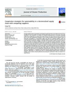
are being extended to mobile manipulation systems [1] [2][3][13]. Typical approaches to motion coordination of redundant systems involve the use of pseudo- or generalized inverses to solve an under-constrained or degenerate system of linear equations, while optimizing some given criterion. These algorithms are essentially driven by kinematic considerations and the dynamic interaction between the end effector and the manipulator's internal motions are ignored. Our approach to controlling redundant systems is based on two models: an end-e�ector dynamic model [10] obtained by projecting the mechanism dynamics into the operational space, and a dynamically consistent force/torque relationship [11] that provides decoupled control of joint motions in the null space associated with the redundant mechanism. These models form the basis for the dynamic coordination strategy we are implementing on the mobile manipulation platforms. With this strategy, the vehicle/arm system can be viewed as the mechanism resulting from the serial combination of two sub-systems: a \macro" structure with coarse, slow, dynamic responses (the mobile base), and a relatively fast and accurate \mini" device (the manipulator). Another important issue in mobile manipulation concerns cooperative operations between multiple vehicle/arm systems [4]{[8]. An example of cooperative operations involving multiple vehicle/arm systems in construction tasks, is illustrated in Figure 1. Our research in cooperative manipulation has produced a number of results which provide the basis for the control strategies we are developing for mobile manipulation platforms. Our approach is based on the integration of two basic concepts: The augmented object [14] and the virtual linkage [15]. The virtual linkage characterizes internal forces, while the augmented object describes the system's closed-chain dynamics. These models have been successfully used in cooperative ma-
Figure 1: Robotics in Construction: Drywall nipulation for various compliant motion tasks performed by two and three PUMA 560 manipulators [16]. The augmented object model we developed for xed base multi-arm robots has been extended to the multiple vehicle/arm systems. The dynamics at the operational point of a multiple vehicle/arm system are described by an augmented object model which is obtained by combining the dynamics of the individual mobile manipulators and the object. Control of this highly redundant system relies on both the dynamically consistent relationships between joint forces and end-e�ector forces for each mobile arm. While providing accurate description of cooperative manipulation, the augmented object and virtual linkage models have been implemented in an architecture that requires some level of centralized control, which is not quite suited for autonomous mobile manipulation platforms. The article presents a new strategy based on the augmented object and virtual linkage models for decentralized cooperative operations between multiple mobile manipulation platforms.
where q is the n joint coordinates and A(q) is the n � n kinetic energy matrix. b(q; q_ ) is the vector of centrifugal and Coriolis joint-forces and g(q) is the gravity joint-force vector. ? is the vector of generalized joint-forces. The operational space equations of motion of a manipulator are [10] �(x)x + �(x; x_ ) + p(x) = F; (2) where x, is the vector of the m operational coordinates describing the position and orientation of the e�ector, �(x) is the m � m kinetic energy matrix associated with the operational space. �(x; x_ ), p(x), and F are respectively the centrifugal and Coriolis force vector, gravity force vector, and generalized force vector acting in operational space.
Redundancy
The operational space equations of motion describe the dynamic response of a manipulator to the application of an operational force F at the end e�ector. For non-redundant manipulators, the relationship between operational forces, F, and joint forces, ? is ? = J T (q)F; (3) where J(q) is the Jacobian matrix. However, this relationship becomes incomplete Dynamics for redundant systems. We have shown that the The joint space dynamics of a manipulator are de- relationship between joint torques and operational scribed by forces is i h ? = J T (q)F + I ? J T (q)J T (q) ?0; (4) A(q)q + b(q; q_ ) + g(q) = ?; (1)
2 Vehicle/Arm Coordination
2
with
J(q) = A?1 (q)J T (q)�(q);
Our study has shown [11] that, in any direction w, the inertial properties of a macro/minimanipulator system are smaller than or equal to the inertial properties associated with the minimanipulator in that direction:
(5)
where J(q) is the dynamically consistent generalized inverse [11]. This relationship provides a
decomposition of joint forces into two dynamically decoupled control vectors: joint forces corresponding to forces acting at the end e�ector (J T F); and that only � a�ect internal motions, � joint forces T T [I ? J (q)J (q)]?0 . Using this decomposition, the end e�ector can be controlled by operational forces, whereas internal motions can be independently controlled by joint forces that are guaranteed not to alter the end e�ector's dynamic behavior. This relationship is the basis for implementing the dynamic coordination strategy for a vehicle/arm system. The end-e�ector equations of motion for a redundant manipulator are obtained by the projection of the joint-space equations of motion (1), by the dynamically consistent generalized inverse J T (q),
�w (�) � �w(�m ):
(7)
A more general statement of this reduced e�ective inertial property is that the inertial properties of a redundant system are bounded above by the inertial properties of the structure formed by the smallest distal set of degrees of freedom that span the operational space.
Coordination Strategy
The reduced e�ective inertial property shows that the dynamic performance of a combined macro/mini system can be made comparable to (and, in some cases, better than) that of the lightweight mini manipulator. The idea behind our approach for the coordination of macro and mini structures is to treat them as a single redundant system. High dynamic performance for the manipulated object task (motion and contact forces) can be achieved with an operational space control system using essentially the fast dynamic response of the mini structure [13]. However, given the mechanical limits on the mini structure's joint motions, this would rapidly lead to joint saturation of the mini-structure degrees of freedom. The dynamic coordination we propose is based on combining the operational space control with a minimization of deviation from the midrange joint positions of the mini-manipulator. This minimization must be implemented with joint force control vectors selected from the dynamically consistent null space of equation (4). This will eliminate any e�ect of the additional control forces on the ende�ector task. Let qi and qi be the upper and lower bounds on the ith joint position qi. We construct the potential function n � X qi + qi �2 VCoordination (q) = kc qi ? 2 ; i=nM +1 (8) where kc is a constant gain and nM is the macro structure's number of degrees of freedom. The gradient of this function
J T (q) [A(q)q + b(q; q_ ) + g(q) = ?] =) �(q)x + �(q; q_ ) + p(q) = F; (6) The above property also applies to nonredundant manipulators, where the matrix J T (q) reduces to J ?T (q).
Inertial Property
A mobile manipulator system can be viewed as the mechanism resulting from the serial combination of two sub-systems: a \macro" mechanism with coarse, slow, dynamic responses (the mobile base), and a relatively fast and accurate \mini" device (the manipulator). The mobile base referred to as the macro structure is assumed to be holonomic. Let � be the pseudo kinetic energy matrix associated with the combined macro/ministructures and �m the operational space kinetic energy matrix associated with the mini structure alone. The magnitude of the inertial properties of macro/mini structure in a direction represented by a unit vector w in the m-dimensional space can be described by the scalar [11] �w (�) = (wT �1?1w) ; which represents the e�ective inertial properties in the direction w.
?Coordination = ?rVCoordination;
3
(9)
Virtual Linkage
provides the required attraction to the mid-range joint positions of the mini-manipulator. The interference of these additional forces with the ende�ector dynamics is avoided by projecting them into the null space of J T (q). This is i h ?Null?Space = I ? J T (q)J T (q) ?Coordination; (10) where ?0 is the joint force in the null space. In addition, joint limit avoidance can be achieved using an \arti cial potential" function [12].
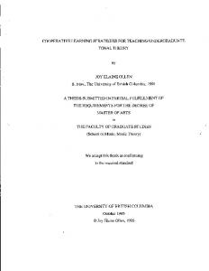
Object manipulation requires accurate control of internal forces. Recently, we have proposed the virtual linkage [15], as a model of internal forces associated with multi-grasp manipulation. In this model, grasp points are connected by a closed, non-intersecting set of virtual links (Figure 2.) In the case of an N-grasp manipulation task, a virtual linkage model is a 6(N ? 1) degree of freedom mechanism that has 3(N ? 2) linearly actuated members and N spherically actuated joints. Forces and moments applied at the grasp points of this linkage will cause forces and torques at its joints. We can independently specify internal Augmented Object forces in the 3(N ? 2) members, along with 3N moments at the spherical joints. Internal The augmented object model provides a descrip- internal forces in object are then characterized by these tion of the dynamics at the operational point for forces andthetorques in a physically meaningful way. a multi-arm robot system. The simplicity of these The relationship applied forces, their equations is the result of an additive property that resultant and internalbetween forces is allows us to obtain the system equations of motion 3 2 from the equations of motion of the individual mof1 � � bile manipulators. Fres = G64 .. 75; (16) The augmented object model is . Fint fN �� (x)x + �� (x; x_ ) + p�(x) = F� ; (11) where Fres represents the resultant forces at the with N X operational point, Fint the internal forces and fi (12) the forces applied at the grasp point i. G is called �� (x) = �L (x) + �i (x); i=1 the grasp description matrix, and relates forces apwhere �L (x) and �i(x) are the kinetic energy ma- plied at each grasp to the resultant and internal trices associated with the object and the ith ef- forces in the object. Furthermore, G can be writfector, respectively. The vector, �� (x; x_ ), of cen- ten as trifugal and Coriolis forces also has the additive G = [ G1G2 ::: GN ]; property where each Gi represents the contribution of the N X (13) ith grasp to the resultant and internal forces felt by �� (x; x_ ) = �L (x; x_ ) + �i (x; x_ ); the object. Also, Gi can be further decomposed i=1 � � where �L (x; x_ ) and �i (x; x_ ) are the vectors of cenres;i ; trifugal and Coriolis forces associated with the obGi = G Gint;i ject and the ith e�ector, respectively. Similarly, the gravity vector is where Gres;i is the contribution of Gi to the resulN tant forces in the object and Gint;i to the internal X (14) ones. p�(x) = pL (x) + pi(x); i=1 The inverse G?1 provides the forces required at the grasp points to produce the resultant and inwhere pL (x) and pi(x) are the gravity vectors asth ternal forces acting at the object. sociated with the object and the i e�ector. The generalized operational forces F� are the resultant 2 3 of the forces produced by each of the N e�ectors f1 � � 6 .. 7 = G?1 Fres : at the operational point. (17) 4 . 5 Fint N X fN (15) F� = Fi : i=1 Similarly, G?1 can be written as
3 Cooperative Manipulation
4
Figure 2: The Virtual Linkage tional point, using equation (16) 3 2 fs;1 � � Fres;s = G64 .. 75: . Fint;s fs;N The centralized control strategy consists of (i) a uni ed motion and force control structure for the augmented object corresponding to the resultant force vector, Fres ; and (ii) a force control vector, Fint, corresponding to the internal forces acting on the virtual linkage. These are
3 2 G1 G?1 = 64 ... 75 ; GN
with
Gi = [ Gres;i Gint;i ];
where Gres;i represents the part of Gi that correspond to the resultant forces at the object; and the matrix Gint;i represents the part corresponding to the internal forces.
Fres = Fmotion + Fcontact;
(18)
where Fmotion = �^ � F�motion + �^� + p^� ; (19) Fcontact = �^ � F�contact + Fcontact;s: (20) �^ �, �^� , and p^� represent the estimates of �� , �� , and p� . The vector F�motion and F�contact represent the inputs to the decoupled system. is the generalized selection matrix associated with motion control and , its complement, is associated with force control. The control structure for internal forces is Fint = �^ � F�int + Fint;s; (21) where the vector F�int represents the inputs to the decoupled system. A suitable control law can be selected to obtain F�motion , F�contact and F�int.
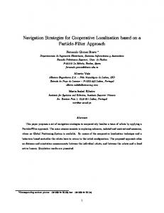
Centralized Control Structure For xed base manipulation, the augmented object and virtual linkage have been implemented in multiprocessor system using a centralized control structure. This type of control is not suited for autonomous mobile manipulation platforms. Before presenting the decentralized implementation, we begin with a brief summary of the centralized control structure. The overall structure of the centralized implementation is shown in Figure 3. The force sensed at the grasp point of each robot, fs;i, is transformed, via G, to sensed resultant forces, Fres;s, and sensed internal forces, Fint;s, at the opera5
-
- e? - Augmented Object Fforce;d and -+ e - Virtual -6 Fint;d - e- Linkage + - 6 Controller xd
+
f1
Fres
Fint -
G?1
x - J1T ?1- Robot (1) - Fwd. fs;11-Kin. Virtual
x
F Linkage res;s xN- Model Fint;s fN- T ?NFwd. f JN Robot (N ) Kin. s;Np p p
p p p
p p p
Figure 3: Centralized Control xd
-
Fforce;dFint;d
-
Grasp
xd;1 fd;1
Kinematics
Linkage
x1 fs;1
- Motion/Force fN- T ?N- Robot (N )- Fwd. JN Kin. - Controller 66
xN fs;N
p p p
and Virtual
- Motion/Force f1 - T ?1- Robot (1) - Fwd. J1 Kin. - Controller 6p 6 p
xd;N fd;N
p p p
Figure 4: Decentralized Control Structure The control forces of the individual mobile ma- feedback control loops are then developed at each grasp point. The task transformation and the denipulator, fi, are given by using equation (17), sign of the local controllers are accomplished in 2 3 f1 consistency with the augmented object and virtual � � 6 .. 7 = G?1 Fres : linkage models. The overall structure of the pro4 . 5 Fint posed decentralized control structure is shown in fN Figure 4. The local control structure at the ith grasp point The above strategy has been successfully implemented for two and three PUMA 560 arms [16]. is fi = fmotion;i + fforce;i : (22) The control vectors, fmotion;i, are designed so Decentralized Control Structure that the combined motion of the various ith grasp In a multiple mobile robot system, each robot has points results in the desired motion at the object real-time access only to its own state information operational point. On the other hand, the vecand can only infer information about the other tors fforce;i create forces at the grasp points, whose robots' grasp forces through their combined ac- combined action produces the desired contact and tion on the object. In the decentralized control internal forces on the object. structure we propose, the object level speci caThe motion control at the ith grasp point is tions of the task are transformed into individual � fmotion;i = �^ �;i fmotion;i + �^�;i + p^�;i; (23) tasks for each of the cooperative robots. Local 6
where the desired resultant forces are
with
�^ �;i = �^ g;i + Gres;i �^ L GTres;i ; (24) where �^ g;i is the kinetic energy matrix associated with the ith e�ector at the grasp point. The second term of equation (24) represents the part of �^ L assigned to the ith robot and described at its grasp point. The vector, �^�;i, of centrifugal and Coriolis forces associated with the ith e�ector is
Fres;d = Fcontact;d;
(31)
where Fcontact;d is the desired contact force vector. The assumptions in the above control structure is that the object is rigid and that there is no slippage at the grasp points. Gripper slip in the real system will result in errors in the grasp kinematic computation and inconsistencies with the virtual linkage model. To compensate for these e�ects, (25) some level of communication between the di�erent �^�;i = �^g;i + Gres;i �^L ; platforms will be needed for updating the robot where �^g;i is the centrifugal and Coriolis vector of state and modifying the task speci cations. The the ith robot alone at the grasp point. Gres;i�^L rate at which this communication is required is represents the part of �^L assigned to the ith robot much slower than the local servo control rate. Such and described at its grasp point. Similarly, the communication can be achieved over a radio Ethgravity vector is ernet link (at 10-20 Hz). p^�;i = p^g;i + Gres;i p^L ;
(26)
4 Experimental Platforms
where p^g;i is the gravity vector associated with the ith end e�ector at the grasp point. Gres;i p^L represents the part of p^L assigned to the ith robot and described at its grasp point. The sensed forces at the ith grasp point, fs;i, combine the contact and internal forces felt at the ith grasp point, together with the acceleration force acting at the object. The sensed forces associated with the contact and internal forces alone, fs�;i , are therefore obtained by subtracting the acceleration e�ect from the total sensed forces � � fs�;i = fs;i ? Gres;i �^ L x d + �^L + p^L : (27)
Recently, we have designed and built two autonomous mobile manipulation platforms (Figure 5). The Stanford Assistant Mobile Manipulator(SAMM) platforms have been developed in collaboration with Nomadic Technologies and Oak Ridge National Laboratories. Each platform consists of a PUMA 560 arm mounted on a holonomic mobile base (Figure 6). The PUMA manipulator is equipped with a 6-axis force sensor on the wrist, and an electric two ngered gripper. The base consists of three \lateral" orthogonal universal-wheel assemblies which allow the base to translate and rotate holonomically in relatively at o�ce-like environments [9]. The base houses two Personal Computers, the motor ampli ers for both the base and arm, and batteries for approximately two hours of autonomous operation. In addition, a 1500 Watt AC power supply is included for tethered operations. Selection between on-board and tethered operations can be made while the robot is in operation. Environmental sensing is currently provided by 48 sonars divided into two rings encircling the base. Sonars in the upper and lower rings re simultaneously to allow through cross-echoes. This allows the detection of objects even if they are located in the middle of the two sonar rings. We are currently working on adding vision capabilities to allow for more complex tasks. The two Personal Computers with 90MHz Pentium processors were selected over other competing technologies because of their relatively low cost and power consumption and the large selection of
Here, the object desired acceleration has been used instead of the actual acceleration, which would be di�cult to evaluate. The force control part of equation (22) is � fforce;i = �^ �i fforce;i + fs�;i; (28) � where fforce;i represents the input to the decoupled system associated with the contact forces and in� ternal forces. fforce;i can be achieved by selecting � fforce;i = ?Kf (fs�;i ? fd;i) ? Kvf f_s�;i :
(29)
The vector fd;i is the desired force assigned to the ith mobile manipulator. Using equation (17), this vector is 2 3 fd;1 � � 6 .. 7 = G?1 Fres;d ; (30) 4 . 5 Fint;d fd;N 7
Figure 5: Stanford Mobile Platforms add-on cards. Also, this architecture will continue to be easily upgraded as computer technology advances. The two computers in each robot are the heart of the multi-processing architecture. On each platform, one computer is devoted to robot control and other real-time tasks. The second computer is responsible for navigation, path planning, communication and other less time-critical functions. Within the robot, the two computers communicate with each other through a wire Ethernet backbone. Communication between robots or with other workstations is accomplished via a radio Ethernet link. This architecture is illustrated in Figure 7. The control computer, running the real-time operating system VxWorks, interfaces with the robot via an o�-the-shelf, compact, modular multi-axis controller which provides 12 encoders channels, 16 D/A channels and 8 A/D channels on a single EISA backplane slot. This is used to read the joint positions of the arm and base and send the motor torques to the ampli ers. Information from the force sensor is received via a ber optic link through a dedicated interface board at speeds of up to 1000Hz. In addition, the control computer communicates via memory-mapped,
dual-ported RAM with a Motorola 6811 microcontroller board. This board provides basic watchdog functions such as enabling and disabling ampli ers and motor brakes, and processing assorted error signals. The navigation computer running the Linux operating system is responsible for tasks that do not require real-time performance. These include path planning and modi cation, environmental sensing and communication with the other robots and the outside world. The sonar ring and timing is accomplished with a Motorola 6811 microprocessor board identical to the one used in the control computer. This frees almost all of this computer's processing power for planning, navigation and self localization. In the future, this computer will also perform some vision processing. A hard disk with 1 GB capacity is provided for completely autonomous startup and development. The control strategies discussed above have been successfully implemented in a system of two platforms. The dynamic coordination strategy has allowed full use of the relatively high bandwidth of the PUMA. Object motion and force control performance with these mobile platforms are comparable with the results obtained with xed base PUMA manipulators. 8
Radio Ethernet
Workstation
PERCEPTION/ PLANNING LEVEL
J
PC BUS
Vision Board
Sensor Board
CPU
Ethernet
R
Control Board
WatchDog Board
CPU
PC BUS
CONTROL LEVEL
Figure 6: Platform Components
Figure 7: SAMM Architecture
5 Conclusion
Stef Sonck and Dave Williams who have made signi cant contributions to the design and construcWe have presented extensions of various opera- tion of the Stanford robotic manipulation plattional space methodologies for xed-base manip- forms. ulators to mobile manipulation systems. A vehicle/arm platform is treated as a macro/mini structure. This redundant system is controlled using a dynamic coordination strategy, which allows the mini structure's high bandwidth to be fully uti- [1] Ullman, M., Cannon, R., \Experiments in Global Navigation and Control of a Freelized. For cooperative operations, we have develFlying Space Robot," Proc. Winter Annual oped a new decentralized control structure based Meeting, Vol. 15, 1989, pp. 37-43. on the augmented object and virtual linkage models that is better suited for mobile manipulator [2] Umetani, Y., and Yoshida, K., \Experimensystems. tal Study on Two-Dimensional Free-Flying Vehicle/arm coordination and cooperative operRobot Satellite Model," Proc. NASA Conf. ations have been successfully implemented on two Space Telerobotics, 1989. mobile manipulator platforms developed at Stanford University. [3] Papadopoulos, E., Dubowsky, S., \Coordinated Manipulator/Spacecraft Motion Control for Space Robotic Systems," Proc. IEEE Int. Conf. Robotics and Automation, 1991, pp. 1696-1701. The nancial support of Boeing, General Motors, Hitachi Construction Machinery, and NSF (grants [4] Zheng, Y.F. and Luh, J.Y.S., \Joint Torques IRI-9320017 and CAD-9320419) is gratefully acfor Control of Two Coordinated Moving knowledged. Many thanks to Alan Bowling, Oliver Robots," Proc. IEEE Int. Conf. Robotics and Brock, Francois Pin, James Slater, John Slater, Automation, 1986, pp. 1375-1380.
References
Acknowledgments
9
[5] Uchiyama, M. and and Dauchez, P., \A sym- [11] Khatib, O., \Inertial Properties in Robotics metric Hybrid Position/Force Control Scheme Manipulation: An Object-Level Framework," for the coordination of Two Robots," Proc. Int. J. Robotics Research, vol. 14, no. 1, IEEE Int. Conf. Robotics and Automation, February 1995. pp. 19-36. 1988, pp. 350-356. [12] Khatib, O., \Real-Time Obstacle Avoidance [6] Hayati, S., \Hybrid Position/Force Control of for Manipulators and Mobile Robots," Int. J. Multi-Arm Cooperating Robots", Proc. IEEE of Robotic Research, vol. 5, no. 1, 1986, pp. Int. Conf. Robotics and Automation, 1986, 90-98. pp. 1375-1380. [13] Russakow, J. and Khatib, O., \A New Con[7] Tarn, T. J., Bejczy, A. K., and Yun, X., \Detrol Structure for Free-Flying Space Robots," sign of Dynamic Control of Two CooperatInt. Symposium on Arti cial Intelligence, ing Robot Arms: Closed Chain Formulation." Robotics and Automation in Space, 1992, pp. Proc. IEEE Int. Conf. Robotics and Automa395-403. tion, 1987, pp. 7-13. [14] Khatib, O., \Object Manipulation in a Multi[8] Adams, J. A., Bajcsy, R., Kosecka, J., E�ector Robot System", Robotics Research Kumar, V., Mandelbaum, R., Mintz, M., 4, R. Bolles and B. Roth, eds., pp. 137-144, Paul, R., Wang, C., Yamamoto, Y., and Cambridge: MIT Press 1988. Yun, X.,\Cooperative Material Handling by Human and Robotic Agents: Module De- [15] Williams, D. and Khatib, O., \The Virtual Linkage: A Model for Internal Forces in velopment and System Synthesis," Proc. Multi-Grasp Manipulation," Proc. IEEE Int. IEEE/RSJ Int. Conf. Intelligent Robotics and Conf. Robotics and Automation, 1993, pp. Systems, 1995, pp. 200-205. 1025-1030. [9] Pin, F. G. and Killough S. M., \A New Family of Omnidirectional and Holonomic Wheeled [16] Williams, D. and Khatib, O., \Multi-Grasp Manipulation," IEEE Int. Conf. Robotics and Platforms for Mobile Robots," Oak Ridge NaAutomation Video Proceedings, 1995. tional Laboratory Technical Reports, 1994. [10] Khatib, O., \A Uni ed Approach to Motion and Force Control of Robot Manipulators: The Operational Space Formulation," IEEE J. Robotics and Automation, vol. 3, no. 1, 1987, pp. 43-53.
10