Formal Semantics for Refinement Verification of Entreprise Models
THÈSE NO 4210 (2008) PRÉSENTÉE le 31 octobre 2008 À LA FACULTE INFORMATIQUE ET COMMUNICATIONS Laboratoire de modélisation systémique SECTION DES SYSTÈMES DE COMMUNICATION
ÉCOLE POLYTECHNIQUE FÉDÉRALE DE LAUSANNE POUR L'OBTENTION DU GRADE DE DOCTEUR ÈS SCIENCES
PAR
Irina Rychkova Master of Applied Mathematics and Physics, Moscow Institute of Physics and Technology, Russie et de nationalité russe
acceptée sur proposition du jury: Dr M. Rajman, président du jury Prof. A. Wegmann , directeur de thèse Dr T. Baar, rapporteur F. Bouchet, rapporteur Prof. V. Kuncak, rapporteur
Lausanne, EPFL 2008
gÉ itÄxÇà|Ç
iv
Acknowledgments I would like to sincerely thank my thesis director Professor Alain Wegmann for his guidance and support during my work at EPFL, and especially for the energy and time he dedicated to this dissertation. I very much appreciate the enthusiasm with which he examines every new idea and his suggestive comments: working with him was always interesting and motivating. I would also like to thank him for giving me an opportunity to complement my PhD with a practical experience, and for supporting my internship at adidas-Group. This experience adds a value to my research results and has a very important impact on my professional life. I would like to express my gratitude to Professor Viktor Kuncak, whose ideas helped me to structure my research matter. I want to especially thank him for being always ready for discussions: owing to his suggestive remarks, my reasoning has acquired the necessary rigor and evolved to an approach presented in this dissertation. My greatest thanks I address to the other members of my PhD cometee: Dr. Thomas Baar, who gave an important feedback on my work, and Mr. Frederic Bouchet, who contributed to my thesis with valuable industrial insights, and Dr. Martin Rajman, who kindly accepted the role of the president. I also like to thank Ian F. Alexander (Scenario Plus), Dr. Ilia Bider (IbisSoft), Professor Donald C. Gause (Savile Row LLC; Binghamton University), Dr. Thomas Langenberg (McKinsey), Dr. Alexander Samarin (Teamlog S.A.), who dedicated their time to read about my research and to participate in my inquiry. Their comments helped me better understand the practical value of my research and to prioritize the directions of the future work.
I am also grateful to my colleagues at LAMS: Pavel, Andrey, Jose-Diego, and Lam-Son for the interesting discussions and valuable comments that helped me during my work; I especially thank Gil for his knowledge management, his remarkable talent to put things on their places, and for his English lessons. I also greatly acknowledge the efforts of Angela, Danielle, and Patricia, who make the complex engine of our research team working smoothly. My sincere thanks to Holly, who contributed to my dissertation as an English editor and who, perhaps, would significantly improve this section as well. In addition, I would like to thank my language professors at EPFL Centre de Langue : Mme Michele Amiot et Mme Jacqueline Allouch, qui m’ont amenées dans le monde de langue la plus belle en Europe. v
I wish to thank my friends, who made these six years in Switzerland the unforgettable part of my life. I thank Kerstin for her optimism, energy, and for being my best training partner and strategic consultant; Alexei: without him I would have never looked at the world from the altitude of 4807m; Dmitry, for his passion to photography and his valuable master-classes in the Alps. I would like to acknowledge here my dear friends who will always stay for me “the Doctoral School”: Sarunas, Ivana R., Maciek, Marta, Michal, Kasia, Ivana J, Denis, Natasha, Gleb, Adriana, Wojtek, Maxim, Dan, and a dozen of others. I thank you guys for making Lausanne and EPFL home for me, for being the never-exhausting source of fun, for all our time spent together hiking, skiing, travelling, celebrating, for zillions of scientific and notexactly-scientific discussions, lunches, beers, dinners, and simply for being here all this time!
In addition, I wish to thank my family: my brother-in-law Slava and my parents-in-law Tatiana and Sergei, who also contributed to my work with their interesting comments. I sincerely thank my parents Tamara and Youri for all what they gave to me and for supporting me even through the great distance between Samara and Lausanne.
My last words of gratitude I address to my husband Valentin: during all these years of my PhD he was always next to me with his advice, valuable comments, encouragements, and his care.
vi
Abstract In this dissertation we investigate how Business/IT alignment in enterprise models can be enhanced by using a software engineering stepwise refinement paradigm. To have an IT system that supports an enterprise and meets the enterprise business needs, management seeks to align business system with IT systems. Enterprise Architecture (EA) is the discipline that addresses the design of aligned business and IT systems. SEAM is an Enterprise Architecture method, developed in the Laboratory of Systemic Modeling (LAMS) at EPFL. SEAM defines a visual language for building an enterprise model of an organization. In this work, we develop a theory and propose a technique to validate an alignment between the system specifications expressed in the SEAM language. We base our reasoning on the idea that each system (an organization, a business system, or an IT system) can be modeled using a set of hierarchical specifications, explicitly related to each other. Considering these relations as refinement relations, we transform the problem of alignment validation into the problem of refinement verification for system specifications: we consider that two system specifications are aligned if one is correctly refines the other. Model-driven engineering (MDE) defines refinement as a transformation between two visual (or program) specifications, where a specification is gradually refined into an implementation. MDE, however, does not formalize refinement verification. Software engineering (SE) formalizes refinement for program specifications. It provides a theory and techniques for refinement verification. To benefit from the formal theories and the refinement verification techniques defined in SE, we extend the SEAM language with additional concepts (e.g. preconditions, postconditions, invariants, etc). This extension enables us to increase the precision of the SEAM visual specifications. Then we define a formal semantics for the extended SEAM modeling language. This semantics is based on first-order logic and set theory; it allows us to reduce the problem of refinement verification to the validation of a first-order logic formula. In software engineering, the tools for the automated analysis of program specifications are defined. To use these tools for refinement verification, we define a translation from SEAM visual specifications to formal specification languages. We apply, using case studies, our theory and technique in several problem areas to verify: (1) if a business process design and re-design correspond to high level business process specifications; (2) if a service implementation corresponds to its specifications. These case studies have been presented to a group of domain experts who practice business/IT alignment. This inquiry has shown that our research has a potential practical value.
Key words: Business/IT alignment, visual modeling, formal semantics, refinement, refinement verification, SEAM, Alloy, Jahob.
1
2
Résumé Dans cette thèse nous étudions comment l'alignement Business/IT dans des modèles d'entreprise peut être améliorée en utilisant le ‘raffinement par étapes’ – un paradigme développé en génie logiciel. Pour obtenir un système informatique qui répond aux besoins de l'entreprise, la direction vise à aligner les systèmes informatiques avec le métier. L’Architecture d’Enterprise (EA) est la discipline qui étudie et développe des théories et méthodes pour cet alignement. SEAM est une méthode d’architecture d'entreprise, développée dans le Laboratoire de modélisation systémique (LAMS) à l'EPFL. Dans cette thèse, nous développons une théorie et proposons une technique de validation d’alignement entre les spécifications exprimées dans le langage de modélisation SEAM. Nous fondons notre raisonnement sur l'idée que chaque système (une organisation, un système d'entreprise, ou un système d'information) peut être modélisé en utilisant un ensemble de spécifications hiérarchiques, explicitement liés les uns aux autres. En repensant ces relations comme des ‘relations de raffinement’, nous transformons le problème de l'alignement entre spécifications au problème de validation de raffinement entre ces spécifications. Nous considérons que deux spécifications du système sont alignées si ce raffinement est correct. Le concept de raffinement est défini en Model-Driven engineering (MDE) comme une transformation entre deux spécifications visuelles où une spécification est progressivement affinée et détaillée jusqu’au niveau d’implémentation. Cependant, les règles de la vérification pour le raffinement ne sont pas formalisées en MDE. Le concept de raffinement pour logiciel a été formalisé en génie logiciel. Le génie logiciel fournit, d'ailleurs, une théorie et des techniques pour la vérification du raffinement. Pour bénéficier de ces théories et techniques, nous étendons SEAM avec des concepts de modélisation supplémentaires. Cette extension nous permet d'augmenter la précision de nos spécifications visuelles. Nous définissons une sémantique formelle pour le langage visuelle de SEAM. Cette sémantique est basée sur la logique de premier ordre et sur la théorie des ensembles. Elle nous permet de réduire le problème de la vérification de raffinement à la validation d’une formule de premier ordre. Pour utiliser les outils d'analyse automatique des spécifications de logiciels dans le contexte des spécifications visuelles, nous définissons une traduction des spécifications SEAM dans un langage de spécifications formelle. Nous appliquons la théorie et les techniques que nous avons développées à plusieurs domaines: (1) à la vérification des processus métier par rapport aux spécifications d’organisation de haut niveau; (2) à la vérification d'une implémentation de service par rapport à ses spécifications. Ces études de cas ont été présentées à un groupe d'experts du domaine qui pratiquent l’alignement Business et IT. Cette enquête a montré que notre recherche a potentiellement une valeur pratique. Mots-clés: alignement Business/IT, spécifications visuelles, raffinement, vérification de raffinement, SEAM, Alloy, Jahob.
sémantique
formelle,
3
4
Contents Chapter 1 Introduction ........................................................................................................... 9 1.1 Business /IT Alignment vs. Stepwise Refinement .............................................................. 9 1.2 Verification of Refinement................................................................................................ 10 1.3 The SEAM Method for Enterprise Architecture ............................................................... 10 1.4 Alignment Validation vs. Refinement Verification in SEAM .......................................... 11 1.5 The Structure of this Document ........................................................................................ 12 Chapter 2 The State of the Art............................................................................................. 13 2.1 Theoretical Foundations of this Work.............................................................................. 13 2.1.1 Model Transformations ..................................................................................... 13 2.1.2 Refinement and Refactoring in Software Engineering ..................................... 15 2.1.3 Refinement and Refinement Verification.......................................................... 16 2.1.4 Model Verification ............................................................................................ 17 2.1.5 Formal Semantics for Visual Modeling Languages .......................................... 18 2.2 Visual Modeling Methods and their Consideration of Refinement ................................. 18 2.2.1 Classification Framework for Modeling Methods ............................................ 19 2.2.2 Modeling Methods Overview............................................................................ 19 2.2.3 A Comparison of Modeling Methods................................................................ 22 2.3 Visual Modeling Tools and their Support of Model Refinement and Refinement Verification......................................................................................................................... 23 2.3.1 Classification Framework for Modeling Tools ................................................. 23 2.3.2 Modeling Tools Overview ................................................................................ 24 2.3.3 A Comparison of Modeling Tools .................................................................... 26 Chapter 3 The SEAM Method ............................................................................................. 31 3.1 The SEAM Specification of a System ............................................................................. 31 3.2 Declarative vs. Imperative Action Specifications in SEAM............................................ 35 3.3 The SEAM Metamodel (Abstract Syntax)....................................................................... 36 3.4 The SEAM Semantics and Graphical Notation (Concrete Syntax) ................................. 38 3.4.1 Working Object ................................................................................................. 38 3.4.2 Property ............................................................................................................. 39 3.4.3 Action ................................................................................................................ 40 3.4.4 Action- to-Action (AA-) Relations ................................................................... 40 3.4.5 Action-to-Property (AP-) Relations .................................................................. 43 3.4.6 Localized vs. Joint vs. Distributed actions ........................................................ 44 3.4.7 Shared Properties, Input and Output Parameters, Local Variables ................... 44 3.4.8 Relations with Multiplicities ............................................................................. 45 Chapter 4 Formal Semantics for SEAM Specifications .................................................... 47 4.1 First-Order Logic ............................................................................................................. 48 4.2 Intuition for Set-Theoretical Interpretation of SEAM Modeling Concepts ..................... 49 4.3 Formalization of SEAM Model Elements in FOL........................................................... 52 4.3.1 Working Object ................................................................................................. 52 4.3.2 Property and State ............................................................................................. 52 4.3.3 Host Relations, Property Associations, and Property Compositions ................ 53 5
4.3.4 Action ................................................................................................................ 56 4.3.5 Action-to-Property (AP-) relations.................................................................... 62 4.3.6 Action-to-Action (AA-) relations...................................................................... 63 4.3.7 Distributed Action and Distributed to Localized Action (DALA-) Relations .. 66 4.4 Imperative vs. Declarative Specifications........................................................................ 66 4.5 Instance Creation and Deletion: Local Variables............................................................. 67 Chapter 5 Transformations of Refinement in SEAM and Refinement Verification ...... 69 5.1 Refinement vs. Refactoring.............................................................................................. 69 5.2 Simulation Techniques: the State of the Art .................................................................... 70 5.2.1 Data Refinement with Forward Simulation: (1, 1) - refinement schema .......... 72 5.2.2 ASM Refinement: (m,n) – Refinement Schema ............................................... 73 5.3 Specification Consistency ................................................................................................ 77 5.4 Functional and Organizational Refinement in SEAM ..................................................... 77 5.4.1 Functional Refinement in SEAM ...................................................................... 79 5.4.2 Organizational Refinement in SEAM ............................................................... 81 5.5 Correctness of Functional Refinement............................................................................. 82 5.5.1 Property Refinement ......................................................................................... 82 5.5.2 Behavioural Refinement.................................................................................... 85 5.6 Correctness of Organizational Refinement ...................................................................... 90 5.6.1 Working Object Decomposition and Property Distribution.............................. 90 5.6.2 Refinement of a Localized action with a Joint action ....................................... 92 5.6.3 Refinement of a Localized Action with a Distributed Action........................... 94 Chapter 6 Analysis of SEAM Specifications using Formal Specification Languages..... 99 6.1 Approaches to Formal Verification................................................................................ 100 6.1.1 The Alloy Specification Language and the Alloy Analyzer ........................... 101 6.1.2 The Jahob Verification System ....................................................................... 101 6.2 The 'XYZ' Example........................................................................................................ 103 6.3 Mapping to Alloy ........................................................................................................... 105 6.3.1 Model Elements............................................................................................... 105 6.3.2 Functional Refinement: from an Action as a Whole to an Action as a Composite 108 6.3.3 Organizational Refinement: from a Working Object as a Whole to a Working Object as a Composite................................................................................................... 112 6.4 Automated SEAM to Alloy Translation ........................................................................ 115 6.5 Mapping to Jahob........................................................................................................... 118 6.5.1 From an Alloy Specification to a Jahob Formula ........................................... 118 6.5.2 From a SEAM Specification to a Jahob Program ........................................... 122 Chapter 7 Practical Impact: Application of the Developed Theory in Practice............ 123 7.1 High-Level Design and Analysis of Business Processes: The On-Line Book Store Example ............................................................................................................................ 123 7.1.1 A Business Process Specification in SEAM ................................................... 124 7.1.2 Example: A Sale Process for the On-Line Book Store ................................... 125 7.1.3 Validation of Declarative Business Process Specifications in Alloy.............. 129 7.1.4 Validation of Refinement from LA to DA Using Alloy Analyzer 4.0............ 131 7.2 Specification and Alignment Verification of Services in ITIL: The Gas Incident Service Case Study ........................................................................................................................ 132 7.2.1 Case Study: Gas Incident Service ................................................................... 133 7.2.2 Validation of a Service and its Construction in Alloy .................................... 135 7.2.3 Validation of Refinement from SLA (Modeled as SEAM Localized Action) to OLAs (Modeled as SEAM Distributed Action) Using Alloy Analyzer 4.0.................. 138 6
7.3 Practical Feedback ......................................................................................................... 139 Summary ....................................................................................................................... 140 Chapter 8 Conclusion.......................................................................................................... 143 8.1 Future Work ................................................................................................................... 144 8.1.1 Complexity Reduction, Usability.................................................................... 144 8.1.2 Formal Semantics ............................................................................................ 144 8.1.3 Refinement ...................................................................................................... 145 Bibliography ........................................................................................................................ 147 Appendix A .......................................................................................................................... 155 Alloy Specification of the XYZ Example ..................................................................... 155 Appendix B........................................................................................................................... 163 Jahob Formulas for the XYZ Example ......................................................................... 163 Appendix C .......................................................................................................................... 169 Practical Feedback......................................................................................................... 169 List of Figures ....................................................................................................................... 177 List of Abbreviations............................................................................................................. 181 List of Publications................................................................................................................ 183 Curriculum Vitae................................................................................................................... 185
7
8
Chapter 1 Introduction In providing services to stakeholders, many organizations depend heavily on their IT infrastructure. Insuring that IT does what business needs is a very important issue for management and is achieved by Business-IT alignment. Business-IT alignment is defined in [110] as “.. an ongoing process that will optimize the relational mechanisms between the business and IT organization by working on the IT effectiveness of the organization in order to maximize the business value from IT.”. Enterprise Architecture (EA) is the discipline that addresses the design of aligned business systems and IT systems. Enterprise Architecture methods provide techniques, tools, and guidelines for building an enterprise model of an organization. Traditionally, an enterprise model is a set of visual specifications of an organization that has a hierarchical structure. Each hierarchical level specifies an organization from different perspectives, e.g. business, organizational, or IT. The main challenge of enterprise modeling is to insure that the specifications representing an organization at the IT level correspond to the specifications at the higher levels, where the value for this organization is defined.
1.1 Business /IT Alignment vs. Stepwise Refinement Enterprise models are mostly represented in graphical form that we call visual specifications. The main advantage of visual specifications is that they enable discussion about the model among different stakeholders. However, the lack of precision and formally-defined semantics makes a further analysis (such as a comparison of different versions of the model, or an alignment validation between models) complicated, if at all possible. Software Engineering (SE) provides an underlying theory and a set of techniques for program specification analysis. Program specifications, similarly to visual specifications, are used to describe systems: their construction and functionality. Stepwise refinement is a paradigm for semantic program construction, originally proposed by Dijkstra [31] and Wirth [111]. It is based on the idea that a program can be developed through a sequence of refinement steps starting from an abstract specification. At each step, the refined (‘concrete’) specification is proven to be a correct refinement of the ‘abstract’ specification. In this dissertation, we make a correspondence between program specifications in SE and visual system1 specifications in order to benefit from theories and tools exist for program specification analysis. We explore the idea that, similarly to program specifications, each visual specification can be seen as a refinement of another visual specification. This describes the organization at a more abstract organizational level. 1
In this work, we will use the generic term system to discuss organizations, business systems, IT systems, and their alignment.
9
As a main contribution of this dissertation, we reduce the problem of alignment verification in enterprise visual specifications to the problem of refinement verification, defined for program specifications in SE.
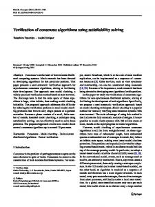
1.2 Verification of Refinement Refinement correctness for programs is validated by establishing simulation relations [65] between the abstract and concrete specifications. In other terms, the refinement is correct if the concrete specification simulates the abstract specification. A simulation relation R (also called a refinement relation) puts into correspondence the states of abstract and the concrete specifications. The concrete specification is said to be a correct refinement of the abstract specification when, starting at the corresponding initial states, both specifications will terminate in the corresponding final states (Fig. 1-1).
Figure 1-1: Refinement verification by simulation.
The same way, we define semantics for visual system specifications in terms of states and transitions between them. Therefore, the refinement verification schema, illustrated in Fig.11, is also valid for visual specifications. We proceed with an automated validation of refinement, providing a mapping of visual specifications to a formal language, for which tools for automated analysis already exist.
1.3 The SEAM Method for Enterprise Architecture We implement the theory of refinement verification in order to validate the alignment between systems specified in SEAM [108]. SEAM is an Enterprise Architecture (EA) method that provides a visual notation for modeling systems, including business and IT systems. In SEAM, a system is represented by a working object. A SEAM model of a system contains a set of specifications of the working object structured in two hierarchies: an organizational level hierarchy and a functional level hierarchy. A working object, modeled as a whole at one organizational level, can be represented as a composite on the next organizational level. This maintains the explicit traceability between organizational levels. Fig. 1-2 (a) illustrates a working object WObject1 as a whole; Fig. 1-2 (b) illustrates this working object on the next organizational level (i.e. seen as a composite). A working object, as a whole, has properties and localized actions; A working object, as a composite, has component working objects and joint or distributed actions between them.
10
Figure 1-2: a) Working object as a whole (org. level 1, func. level 1) is specified with a property and a localized action. Properties represent data the working object stores or operates with. A localized action changes the state of the working object by modifying its properties; b) Working object as a composite (org. level 2, func. level 1) is specified with its component working objects and a joint action between them.
A property or an action, modeled as a whole at one functional level, can be represented as a composite on the next functional level. This maintains the explicit traceability between functional levels:
Figure 1-3: Working object as a whole (org. level 1, func. level 2), specified with a property seen as a composite and a localized action seen as a composite.
1.4 Alignment Validation vs. Refinement Verification in SEAM This work applies the paradigm of stepwise refinement for SEAM specifications and describes how SEAM specifications can be aligned and how this alignment can be validated. To rigorously reason about SEAM specifications and their refinements, we provide a formal semantics for SEAM specifications and their refinements, based on set theory and first-order logic (FOL)2. To formalize the criteria of refinement correctness, we use a theory of data refinement from [72][51][101] and more generalized form of refinement from [15][16]. Based on the formal semantics, we specify a mapping of SEAM visual specifications to the specification languages (e.g. Alloy [59], Jahob [63]) for further refinement verification. We interpret the result of refinement verification as the validity of the alignment between visual specifications. The contributions of this dissertation can be summarized as follows: • Formalization of the initial set of SEAM modeling concepts using first-order logic; • Classification of SEAM refinements; • Identification of the modeling concepts, missing in the current version of SEAM and required for refinement verification (i.e. action preconditions, postconditions etc.); • Formalization of the initial set of SEAM modeling concepts; • Definition of refinement correctness for SEAM using a forward simulation for data refinement from [72][65] and generalized forward simulation from [16]; 2
FOL is a system of formal reasoning also known as a first-order predicate calculus [53][18].
11
• •
Mapping of SEAM specifications to the Alloy specification language [59] for the validation of refinement using the Alloy Analyzer tool; Mapping of SEAM specifications to the Jahob formulae [63] in order to generate a formal proof of refinement correctness using the Jahob formDecider.
1.5 The Structure of this Document In Chapter 2 of this document, we analyze the state of the art. It comprises (a) theoretical foundations in specification development using refinement, formal refinement verification, and visual modeling and (b) practical applications of modeling techniques developed in academia and in the industry. In Chapter 3 we present the SEAM method. This work extends the original set of SEAM modeling concepts. In this chapter, we specify the graphical notation and semantics for the extended SEAM language. In Chapter 4 we present the formalization of SEAM modeling concepts using first-order logic (FOL). In Chapter 5 we classify refinements in SEAM and specify correctness for each refinement type. We use forward simulation for data refinement and generalized forward simulation, defined in the ASM refinement method, as proof methods for refinement correctness. We reduce a problem of refinement verification in SEAM to a proof of validity of a corresponding FOL-formula. In Chapter 6 we present two techniques for the automated refinement verification in SEAM: The first technique is based on use of the Alloy Analyzer - a tool for analyzing models written in the Alloy specification language; the second technique is a formal proof of refinement correctness in the Jahob verification system. In Chapter 7 we present the practical impact of the developed theory. In this chapter, we discuss in detail two examples that illustrate how the achievements of this thesis can be implemented to verify: (1) If business process design and re-design correspond to the high level business process specification (Book Store example); (2) If service implementation corresponds to its specification (SIG example). In Chapter 8 we present our conclusion and discuss a future work. At the beginning of each chapter, we give an overview of the chapter’s content. For the reader interested in business / IT alignment and the practical aspects of the proposed theory, we recommend reading Chapter 2: it provides a state of the art. Then read briefly Chapters 3 and 6, where the SEAM notation and the rules of transformation of SEAM models to formal specifications are explained. And then proceed with Chapters 7 and 8: they illustrate our technique on the examples and provide a practical feedback. For the reader interested in modeling languages and their semantics, we recommend reading Chapters 2, 3, 4 of this document, then proceed with Chapters 6 and 7. For the reader interested in formal methods and their implementation, we recommend reading Chapters 3, 4, 5, 6, and 7 of this document.
12
Chapter 2 The State of the Art This dissertation reports the results of an interdisciplinary research that involves the following areas of information science, and computer science: Enterprise Architecture, Model Driven Engineering, Visual Modeling Languages, and Formal Methods and Languages. In the first part of this chapter we make an overview of the work, which describes the theoretical foundations of this Ph.D: In Section 2.1 we introduce the term of model transformation as it is defined in Model Driven Engineering (MDE). In Section 2.2 we provide an overview of the existing theories and the approaches to refinement verification: model checking and theorem proving. In Section 2.3 we give a definition of the semantics for visual modeling languages and explain the role of formal semantics in the process of refinement verification. In the second part of this chapter, we study how model transformations (namely, model refactoring and refinement) are (1) specified in different visual modeling methods and (2) how they are supported by different modeling tools used in Software and Enterprise modeling: In Section 2.4 we define a comparative framework for visual modelling upon which we analyse five methods developed in the area of Enterprise and Software modelling. In Section 2.5 we define a comparative framework for the modeling tools. Tools, compared to methods, are more user-oriented: some of them (mostly commercial tools) are based on best-practices, whereas the others (research prototypes developed in an academia) implement the theoretical methodologies. We analyse four commercial tools and seven tools, developed in academia. We explore how the automated refinement and the refinement verification are supported by these tools. In Section 2.6 we apply the same frameworks to evaluate the SEAM modelling method and tool.
2.1
Theoretical Foundations of this Work
2.1.1
Model Transformations
Model-Driven Engineering (MDE) is a discipline that defines a set of methods and tools for the software development, where a model plays a central role. Model evolution and elaboration in MDE is described as a result of model transformations. The best known MDE initiative is the Model-Driven Architecture (MDA) software design approach [75]. MDA describes a model evolvement from abstract specifications to their implementations (code). The separation of design from architecture is one of the main principles of MDA. Kleppe et al. [62] provide the following definition of a model transformation: “A transformation is the automatic generation of a target model from a source model, according to a transformation definition. A transformation definition is a set of transformation rules that together describe how a model in the source language can be transformed into a model in the target language. A transformation rule is a description of 13
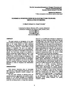
how one or more constructs in the source language can be transformed into one or more constructs in the target language.” Source and target models, in model transformation, are expressed in corresponding languages and are said to be conforming to metamodels. The term metamodel is often associated with a set of rules and definitions, provided by the modelling language. [70] proposes the following dimensions for the categorization of transformations: endogenous/exogenous and horizontal/vertical. A transformation is endogenous if the source and the target models conform to the same metamodel (are expressed in the same language). If the source and the target metamodels are different, then the transformation is exogenous. Exogenous transformations can be also called translations from one language to another. A transformation is horizontal if the source and the target model reside at the same abstraction level. A vertical transformation, respectively, is a transformation, where the source and the target model reside in different abstraction levels. The taxonomy of model transformations is presented in [70].
Figure 2-1: Classification of model transformations in context of Visual modeling.
In context of visual modeling, we distinguish the transformations of visual specifications to executable program specifications, and the transformations of visual specifications to visual specifications. Former transformations are exogenous; latter transformations can be endogenous (if both models are expressed in the same visual modeling language) or exogenous (if a language of the target model is different from the language of the source model). In Fig. 2-1, transformations T1 and T2 specify transformations from a visual specification to a program specification – they are exogenous; T0 specifies a transformation between two visual specifications, where one conforms to a metamodel MM1 and another - to a metamodel MM2. If MM1 = MM2 then T0 is an endogenous transformation. Examples of transformations are: – Synthesis of a higher level (more abstract) specification into a lower-level (more concrete) specification. The result of synthesis of a visual specification is typically a code generation.
14
- Generation of an abstract specification from its implementation (also called a reverse engineering). This transformation is the opposite of a synthesis. The result of reverse engineering is typically a visual specification generated from the program specification. Synthesis and reverse engineering aim at increasing or decreasing the abstraction level of a model; these transformations are vertical transformations (Table 2-1). - Language migration is an exogenous transformation that specifies a translation of a visual (or a program) specification expressed in one language to a visual (or a program) specification expressed in the other language, keeping the same level of abstraction. Language migration is a horizontal transformation. (Table 2-1). In this work, we consider two endogenous transformations: refactoring and refinement. Both refinement and refactoring specify transformations between two visual (or program) specifications expressed in the same language. Refinement changes the internal structure of a specification while keeping the same level of abstraction. Refactoring is a horizontal transformation. Refinement is a transformation, where a specification is gradually refined into an implementation [70]. Refinement is a vertical transformation. The design process in SEAM can be seen as a sequence of the transformations of visual specifications. Based on our classification, the transformations of SEAM specifications are refinements and/or refactorings. Table 2-1 summarizes transformation exogenous/endogenous and vertical/horizontal.
types
along
two
classifications:
Table 2-1 Classification of Model Transformations
HORIZONTAL
VERTICAL
(level of abstraction does not change)
(level of abstraction changes)
ENDOGENOUS (MMs = MMt)
Refactoring
Refinement
EXOGENOUS (MMs MMt)
Language migration
Code Generation, Reverse engineering
Model Driven Engineering provides a classification of model transformations, however it does not provide a theory for reasoning about these transformations. Such a theory can be found in domain of Software Engineering.
2.1.2 Refinement and Refactoring in Software Engineering Transformations of refactoring and refinement are also defined in Software Engineering (SE) to specify transformations of programs. [42] defines refactoring as “the process of changing a software system in such a way that it does not alter the external behavior of the code yet improves its internal structure." Refactoring can be considered as a series of atomic behavior-preserving transformations (also refactorings) which in combination may result in substantial reorganization of the code. Refactoring does not consider transformations, which change a state space of the model. In the domain of software modeling, refactorings for UML class diagrams annotated by OCL constraints are systematized and formalized in [68].
15
Refinement [111] is a more general technique that specifies a stepwise development of the program by adding details or eliminating nondeterminism. As opposed to refactoring, refinement can change a state space and an observable behavior of a model (e.g. adding, removing a field or a method of a class). Thus, refinement specifies a wider class of transformations then refactoring does (see www.refactoring.org). In Software Engineering, the criteria of refactoring/refinement correctness are well specified; therefore these transformations can be verified. Refinement verification techniques are often used to verify refactoring correctness [23], [85]. The semantic correctness of the refactorings for UML class diagrams is presented in [6]. In this work, we formalize all types of transformations defined for SEAM visual specifications as refinements.
2.1.3 Refinement and Refinement Verification Stepwise refinement is a well-known paradigm for semantic program constructions originally proposed in [31] and [111]. It is based on the idea that a program can be developed through a sequence of refinement steps starting from an abstract specification. Different notions of refinement can be found in the literature (see [88] for an overview). We list only a few. A method of program construction based on stepwise data refinement together with proof of refinement correctness was proposed by Hoare [51]. Data refinement and techniques to prove its correctness are presented in [93]. In [15], the Abstract State Machine method of abstract refinable system specifications is introduced. In [16], the Abstract State Machine refinement method is presented. The ASM refinement method generalizes the notion of refinement for an arbitrary number of transitions (run segments) between the initial and the final specification states. Refinement verification is largely based on the use of simulation techniques [65]. By the simulation we understand a correspondence between the states of two systems, where one system is considered a specification and other – its implementation. The simulation proof is based on the establishing of this correspondence. The fact that a simulation between two systems exists shows that any behavior of one system can also be exhibited (simulated) by the other system. The research literature contains a large number of different types of simulations, such as forward simulation, backward simulation, hybrid simulations (i.e. forward-backward and backward-forward simulations) [65][112][50][27], refinement mappings [1], and a generalized forward simulation [15][16][98]. These simulations are differentiated based on the way they relate system specifications and their implementations: for example, forward simulation matches each step of the system implementation with a corresponding step forward of its specification; whereas the backward simulation matches each step of the system implementation with the corresponding step backward of its specification. The simulation techniques will be presented in detail in Chapter 5. In contrast to refinement techniques where an intermediate specification is first proposed and then proved (for example, by simulation) to be a correct refinement of its antecedent, there exists a refinement technique based on calculation [72]. The refinement calculus by Back [7] is an underlying theory of this technique. According to this technique, every intermediate specification can be calculated from the previous one by using refinement laws. The application of these laws enables the reduction of proof obligations and assures refinement correctness. In the context of visual modeling methods, incremental software construction using refinement diagrams is proposed in [8]. Here refinement calculus is used as logic for reasoning on software systems and their evolution. Pons defines in [85] the UML refinement
16
patterns grounded on Object-Z. In [6] refinement for the UML class diagrams and corresponding OCL contracts is specified.
2.1.4 Model Verification When a model (a program or a visual specification) is created or obtained by refining another model, it is important to validate that it is constructed correctly: for example, that it has a certain property. This can be done by formal verification. There are two main approaches to formal verification: model checking [20] and theorem proving based on logical inference [47] [64]. Model checking is an approach for verifying the requirements and design for a vast class of systems. A system, specified as a Kripke structure, is checked against some logical formula that expresses a desired property or requirement of this system. Typically, formal specification languages are used to specify the system, its properties, and requirements. A model M of the system can be considered in model checking as a finite state machine (FSM). A FSM consists of nodes, representing system states, and vertices, presenting transitions between their states. Desired properties of the system are specified as logical formulas. To find out whether the model M with the initial state s satisfies some property φ, (denoted M, s ╞ φ) the state space and all transitions of the model are systematically and exhaustively explored. The major drawback of the model checking is a state explosion problem, which originates from the fact that for real systems the size of the state space grows exponentially with the number of processes [21]. To avoid the state explosion, model checkers implement specific techniques, such as symbolic algorithms and binary decision diagrams (BDD) [54], bounded algorithms [3], counter-example guided abstraction refinement [52], and algorithms based on partial order reduction, or on abstraction. Model checking approaches largely use the counterexample-based algorithms to validate properties of a system, specified as logical formulas. Such algorithms explore the system state space looking for the case, where this formula is violated. This case is called a counterexample; the occurrence of a counter-example demonstrates that the formula is invalid. However, the fact that no counterexample is found does not prove the validity of the formula, because the state space under the exploration is limited. The second approach is an automated theorem proving based on logical inference. Within this approach, the fact that the system specification (a model) satisfies a certain property is expressed as a logical formula. The task is to prove the validity of this formula, deducing it from a set of axioms that exist for the underlying logic (e.g. first-, second-, higher-order logic etc), and hypotheses made about the system. Depending on the underlying logic, the problem of deciding the validity of a theorem varies from trivial to impossible. Theorem proving for the first-order logic (FOL) is widely represented in the literature (see for example [100][99]). Higher-order logic (HOL) operates on predicates and functions of higher order (a higherorder predicate is a predicate that takes one or more other predicates as arguments). It is more expressive and appropriate for a wider range of problems then first-order logic. However the theorem proving procedures for HOL are more complicated [48][74][82]. Despite the fact that automated theorem proving is complex and requires a lot of involvement from the modeler, its application is promising: this approach is not limited by the state explosion problem (the main limitation of model checkers) and can handle the infinite number of states.
17
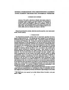
2.1.5 Formal Semantics for Visual Modeling Languages To prove the desired properties of specifications, or to verify the refinement correctness of a visual specification, these specifications should be translated to a formal specification language, accepted by a model checker or an automated theorem prover. Translation (or mapping) rules for a visual specification language can be defined as its formal semantics. The semantics of a visual language L gives a meaning to the constructs and the expressions in this language and can be defined in two ways [10]: "(1) By providing a way in which expressions (and constructs) of L are made (2) By translating the expressions (and constructs) of L into expressions of another language that is already known". Fig. 2-2 illustrates the refinement of a visual specification and its verification. Here M1 and M2 are visual specifications conforming to a source metamodel MMs. T0 is a transformation that specifies a refinement between M1 and M2. We say 'M2 refines M1'. Transformations T1 and T2 specify translations of M1 and M2 to specifications P1 and P2, written in a formal specification languages and defined by formal semantics. We also say that P1 and P2 conform to a target metamodel MMt. Specifications P1 and P2 are formalizations of M1 and M2 in the target language. We identify the refinement between M1 and M2 with the refinement between P1 and P2. For P1 and P2 we can check the refinement correctness using formal verification tools. We interpret the obtained result for M1 and M2: M2 correctly refines M1 if and only if P2 correctly refines P1.
Figure 2-2: Refinement verification of visual specifications is considered as a refinement verification of corresponding specifications written in a formal specification language.
There is a gap between visual modeling languages and formal specification languages: Whereas visual languages are practice-oriented and tend to specify the system avoiding exhaustive details, formal specification languages demand a high precision in model definition. This gap makes translations between specifications complicated. To define formal semantics for visual specifications, the level of precision of these specifications should be increased by introducing new elements to the visual modeling language.
2.2
Visual Modeling Methods and their Consideration of Refinement
Many modeling frameworks and methods in the domain of enterprise modeling, system modeling, and software modeling have emerged in the last decades. See for example [77][78][81][32][114][35][45]. Some of those are discussed and compared in [97]. In this section we analyze some of the methods that we consider the most relevant to the problem of refinement verification.
18
2.2.1 Classification Framework for Modeling Methods Visual modeling methods in Software and Enterprise modeling can be classified based on the way they organize their specifications and guide the modeling process: Some methods define several types of highly specialized diagrams, whereas the others use one diagram type; some methods keep their diagrams explicitly related (aligned) and provide mechanisms for this alignment, and the others define loosely coupled sets of specifications, leaving the relationships between these specifications to a modeler’s consideration. These characteristics of modeling methods affect the way these methods support refinement. We develop the following criteria to classify different modeling methods: 1. Diagram Types We distinguish the modeling methods that define one diagram type for its specifications and those that define many specific diagrams (e.g. UML). 2. Model Structure We distinguish a plain or hierarchical model structure. A hierarchical structure enables ‘zooming in and out’ into model details by switching hierarchical levels. In the plain model, the system is represented by a collection of complementary views that capture different aspects of the system. 3. Traceability Traceability is a relationship between elements in different specifications, which enables a designer to carry out an impact analysis. For the model with a plain structure, the traceability between different views is important to maintain the model consistency. When the model is structured hierarchically, the traceability between specifications at different levels helps to verify the refinement correctness. 4. Refactoring/Refinement Rules We distinguish the methods that specify the rules of refinement or refactoring for their specifications, and those that do not restrict the modeler and leave the refinement process to the modeler’s discretion.
2.2.2 Modeling Methods Overview We consider in detail the following modeling methods: UML2.0 and its extension SysML; BPMN DEMO OPM ADORA UML 2.0 [77] is a de-facto standard for software development. UML proposes 13 diagram types that enable modeling various system aspects. These diagrams are divided in three groups: structure, behavior, and interaction diagrams. Structure diagrams include: • Class diagram • Component diagram • Composite structure diagram • Deployment diagram • Object diagram • Package diagram + Behavior diagrams are: 19
• • •
Activity diagram + State Machine diagram + Use case diagram + Interaction diagrams relate a system structure defined in the structure diagrams with its behavior, specified in behavior diagrams. These diagrams include: • Communication diagram • Interaction overview diagram • Sequence diagram • UML Timing Diagram There is a semantic relationship between the UML diagrams of different types, i.e. they are complementary. Some diagrams in addition have a hierarchical structure (they are marked with ‘+’ in the list). For example, a state machine diagram defines state machines and submachines; activities are composed of activity nodes that can be also activities, etc. Different UML diagrams are complementary but self-contained, which implies that any relationships between the elements in different diagrams have no semantic effect on the model. Traceability in UML can be expressed using traceability relationships. An implementation of traceability typically depends on the tool. IBM Rational software architect [87], for example, provides diagrams and table views of related model elements, broken relationships between model elements, and implied dependencies between model elements. UML 2.0 specification [77] does not address explicitly the traceability issue. UML defines an abstraction relationship between its model elements. This relationship in UML can be used to model stepwise refinement. No explicit refinement rules or classification of refinements is specified in the original UML documentation. It is left to the discretion of the UML practitioners or tools, implementing UML. The official list of UML-based modeling tools is available at http://umldirectory.omg.org/vendor/list.htm. At the time of this work, there are more than 40 products. Systems Modeling Language (SysML) [79] was developed by OMG and based on UML. SysML targets the design of large industrial systems (e.g. aircraft, power plants, etc). It defines nine diagram types; four of them are inherited from UML. SysML defines blocks as modular units of system description. Blocks group both structural and behavioral features (properties, states, operations) to describe a system of interest. The Block Definition Diagram in SysML defines features of a block and relationships between blocks. The Internal Block Diagram in SysML captures the internal structure of a block. Blocks can be decomposed into parts that are also blocks. Business Process Modeling Notation (BPMN) [78] provides a visual notation and formalism for business process model development. This notation is mostly focused on the representation of a system’s behavior and proposes a variety of model elements for its realistic specification. BPMN specifies one diagram type called business process diagram (BPD). In a BPD, two hierarchies can be captured: by using combinations of swim lanes, a hierarchical structure of organizations can be modeled; and by using combinations of BPMN processes, sub-processes, and tasks, organization behavior can be modeled with different levels of details. Traceability between tasks and activities in BPD is explicit and maintained by the sequence and message flows (connections). Modeling expanded sub-processes can be considered as a functional refinement of the business process model. BPMN defines rules for sub-process definition to guarantee that it is consistent with the main process. They can be considered as refinement rules. Swim lanes 20
specify the process participants. Therefore, the definition of multiple lanes for one pool is equivalent to the organizational refinement. At the time of this work, there are 44 existing and 4 planned implementations of BPMN. The complete list of tools is available at http://www.bpmn.org/ . Design & Engineering Methodology for Organizations (DEMO) [29] is an EA framework based on the organizational theory called Language/Action Perspective. The DEMO methodology takes its theoretical origin from the works of Habermas on communicative action [49]. This methodology provides a set of methods for capturing and visualizing business processes and the actors involved in the activities comprising these business processes. DEMO defines its organizational levels based on a communication paradigm. Functional levels are defined in DEMO based on the view of business processes as transactions. DEMO specifies four aspect models (construction, process, state, and action models) and five diagram types for these models (actor - transaction diagram, actor - bank diagram, process - structure diagram, objects - fact diagram, action - rule specification). The construction model specifies the construction of the organization in terms of the transactions, actors, information banks, and information links between them. The process model and the state model are considered as the next detailing level of the construction model – they describe each transaction as a set of states and transitions. The action model specifies the action rules and can be seen as the second detailing level of the construction model. Traceability between modeled aspects is captured in DEMO using cross-model tables. DEMO defines functional and constructional decompositions as techniques for dealing with the complexity of the modeled system. Decompositions can be seen as corresponding refinement types. Object-Process Methodology (OPM) [34][35] proposes a method for the complete integration of the systems' states and behaviors within a single graphical model. OPM defines one diagram type for its models called object process diagram (OPD). The system model in OPM is represented by a collection of OPDs structured as a directed acyclic graph with the top-level system diagram in its root. This diagram is considered at detail level zero. Each node of this graph is an OPD, which specifies in more detail a process from the higher level OPD (a zoomed-in process). Relationships between diagrams can be defined explicitly by specifying a control flow. OPM defines the abstracting and refining of its specifications as subtypes of the process called scaling. There are three modes of refinement in OPM: in-zooming, unfolding, and expressing. OPM defines the rules for refining/abstracting processes. In OPM, there exist three types of hierarchies, defined with respect to the first three fundamental structural relations: aggregation-participation, exhibition-characterization, and generalization-specialization. These hierarchies are equally applicable to objects and to processes. The object-oriented modeling method for software called ADORA (Analysis and Description of Requirements and Architecture) is presented in [44][45]. Models in ADORA are composed of hierarchically structured abstract views. ADORA defines a base view and four aspect views for its models (structural, behavior, user, and context views). The base view specifies the hierarchical structure of the objects of the modeled system. Aspect views are generated by combining the base view with the information that is relevant for the selected aspect. All views are integrated in one coherent model.
21
The mechanism of hierarchical decomposition is applied to views. A view transition in ADORA is a sequence of steps that guarantees the well-formedness of a new view. View transitions for structural, behavioral, and user aspect views are specified [113] and can be considered as refinement rules. View transitions enable an explicit traceability between model elements [113]. ADORA defines a formal refinement calculus semantic for the structural, behavioral, and user views.
2.2.3 A Comparison of Modeling Methods We have analysed the methods from 2.2.2 based on the classification framework defined in 2.2.1. A summary of this evaluation is presented in Table 2-2. Table 2-2 Method
1.Diagram types
2.Model structure
3.Traceability
4.Refactoring/ refinement rules
UML 2.0
13 diagram types
Hierarchical for some (not all) diagrams
Can be modeled using traceability relationship, implicit; no semantic impact is specified
Structural refinement: can be modeled using realization relationship, implicit; Behavioral refinement: implicit.
SysML
9 diagram types
Hierarchical for some (not all) diagrams
Explicit requirements traceability; relations between blocks
Structural, behavioral refinement: using block decomposition
BPMN
1 diagram type
Hierarchical: pools/lanes; process/ subprocess
Explicit for tasks and activities using sequence and message flows;
Behavioral refinement: defined by sub-process modeling; Structural refinement: can be modeled using pools – lanes combination.
DEMO
5 diagram types
Hierarchical
Explicit, using crossmodel tables
Behavioral and structural refinements: using functional and constructional (de)composition
OPM
1 diagram type
Hierarchical
Explicit for processes using a control flow.
Behavioral and structural refinements: in the form of in-zooming, unfolding, and expressing
ADORA
Base view + aspect views
Hierarchical
Explicit, using view transitions
Behavioral and structural refinements: using hierarchical decomposition;
Our analysis shows that most of the methods consider behavioral and structural refinement for their models, however semantics of refinement (criteria of refinement validity) and refinement rules are often left for an implementation of the method.
22
2.3
Visual Modeling Tools and their Support of Model Refinement and Refinement Verification
Modeling methods are largely based on theoretical paradigms; they may exist in a form of the guidelines, and may have no tool support. Modeling tools, compared to methods, are concrete applications. Some of the tools are grounded on modeling methods (e.g. UML, BPMN), whereas the others may have no underlying theory but a set of best practices. Modeling tools usually provide an additional functionality to the methods, such as simulation and verification. Model simulation and verification require details about dynamic and static constraints of a modeled system that are often omitted in the visual model. Therefore, semantics of the visual modeling language needs to be extended. For these purposes, visual models are often annotated with expressions written in other languages, e.g. OCL annotations for UML diagrams. In this section we consider visual modeling tools which implement some of the modeling methods listed above.
2.3.1 Classification Framework for Modeling Tools To answer the question, “How different modeling tools support model analysis and refinement verification?”, we define the following classification framework: 1. A Source Language We classify modeling tools by modeling languages that they support or modeling methods they implement. We call these languages or methods source languages, as the model expressed in this language is used as a source for further processing and analysis. 2. A Constrain Specification Language Apart from the source language, we distinguish two other types of languages that (if defined) characterize the modeling tool: a constraint specification language and a target language. The constraint specification language is a language for annotating visual models in order to extend their semantics and increase their precision. 3. Migration to another Language Some modeling tools use their own means to simulate or verify their models; other tools provide a translation of their models to other (target) languages and profit from the simulation and verification tools, developed for those languages. 4. A Target Language The target language is an executable or verifiable specification language. Visual specifications, written in a source language and annotated with expressions written in a constraint specification language are mapped to the target language for further simulation and/or verification. 5. Simulation is a capability of a modeling tool to simulate or execute the model. 6. Well-Formedness and Consistency Checking is a capability of a modeling tool to check if the model is well-formed (a correct instance of its meta-model) and consistent (semantically non-contradictory).
23
7. Refinement Support is a capability of a modeling tool to provide an assistance in at least one of the following refinement–related activities: • the support of incremental model development, when different parts of a model can be iteratively refined; • the control of refinement consistency, when specific rules are implemented to prevent the model from incorrect refinement; • the refinement synchronization, when the rest of the model is synchronized (adjusted) with respect to the refined model part; • the refinement verification, when the refined model is proven a correct refinement of the initial model with respect to the formal definition of refinement correctness.
2.3.2 Modeling Tools Overview Four commercial tools and seven tools developed in academia (or originated from it) have been selected for our analysis. We find the analyzing of both groups of tools important, because the former group reflects the current needs of practitioners, whereas the latter illustrates the research innovations in the area. For our analysis we have selected the tools that facilitate model simulation, analysis and refinement support. Commercial tools: No Magic - MagicDraw (UML2.0, SysML, BPMN, DoDAF) - www.magicdraw.com/ Telelogic - SystemArchitect (BPMN, DoDAF) www.telelogic.com/products/systemarchitect/index.cfm Metastorm - ProVision (BPMN, Six Sigma, Zachman, TOGAF, DoDAF, UML) www.metastorm.com/products/mpea.asp Intalio - Designer (BPMN) - www.intalio.com/products/designer/ Research prototypes and research based tools: ArgoUML (UML) RoclET (UML, OCL) UML2Alloy (UML, OCL) BPMN2PNML (BPMN) OPCAT (OPM) ADORA (ADORA) DEMOS (ER) MagicDraw is a business modeling tool, developed by No Magic Inc.[67]. MagicDraw UML 15.0 is the latest version of the product by the time of this work. This tool supports UML 2, BPMN notations, and provides a plugin for SysML. MagicDraw supports OCL constraints for its model elements. OCL syntax is validated automatically. The tool supports model decomposition and provides the automated check of model completeness and correctness. Model versioning can serve for refinement support: one can see the changes made between two different versions of a model. To the best of our knowledge, MagicDraw does not provide means to keep track and to validate these changes with respect of the initial model (what we call refinement verification). Telelogic System Architect is a tool for business and enterprise architecture modeling [104]. This tool supports BPMN and provides facilities for planning, modeling, and execution of business process specifications. System Architect has its own simulator for process
24
specifications, called System Architect Simulator II. System Architect complements another Telelogic tool called TAU G2 supporting UML2.0 visual modeling. Metastorm ProVision [86] is a tool for business process modeling and analysis that supports (among the others) BPMN notation for the processes. The tool includes both Monte Carlo and discrete event simulators to define scenarios and perform process simulation. Scenario-based simulation shows how the process will behave under specific conditions. Intalio Designer [56] is an Eclipse-based integrated development environment for BPMN business processes. It is a part of Intalio BPMS 4.0. Intalio designer supports the static process validation and automatic process code generation. Refining processes into subprocesses in Intalio Designer is performed using the in-line sub-process drill-down approach. ArgoUML [4] is an open source UML modeling tool. ArgoUML provides OCL constraint modeling for its diagrams. ArgoUML supports syntax and type checking of OCL constraints using the Dresden OCL toolkit [37]. ArgoUML implements design critics feature to supervise the modeling process and to correct the modeler’s activity. The tool does not mention explicitly its refinement capabilities; however we consider design critics potentially beneficial for the refinement support. RoclET [94] is an open source tool for analysis of UML/OCL specifications. The current version of RoclET supports UML 1.5 class and objects diagrams and provides a parser/ typechecker for annotated OCL 2.0 constraints. RoclET supports the refactoring of UML class diagrams and automatic synchronization of attached OCL constraints. Baar and Marcovi [5] introduce a proof technique for the semantic preservation of refactoring rules for UML class diagrams and OCL constraints. Evaluation of invariants, pre-, and postconditions for object diagrams is also provided by the tool. UML2Alloy [13] is a tool for the analysis of discrete event systems modeled in UML. This tool provides an interactive interface to translate UML diagrams annotated with OCL constraints into Alloy specifications. UML2Alloy tool accepts XMI serializations of UML models developed in some UML modeling tool (e.g. Magic Draw 9.5, ArgoUML). The tool generates text files with Alloy specifications that can be analyzed in Alloy Analyzer 4.0 [3]. The BPMN to Petri net transformer (BPMN2PNML)[17] is a tool that generates Petri Net Markup Language (PNML) [43][83] specifications from BPMN models for further static analysis. The tool accepts XMI serializations of BPMN models generated by existing BPMN modeling tools (e.g. ILOG BPMN Modeler tool). The semantic analysis of BPMN models can be conducted by importing generated PNML specification into the Petri net-based verification tool ProM [33][84]. This tool allows for the verification of the two following properties of BPMN models: the absence of dead tasks, and the absence of improper process completion, which means that any process instance eventually reaches proper completion. Further details can be found in [30]. The Object-Process CASE Tool (OPCAT) [35][80] is a tool for the development and simulation of OPM system specifications. OPCAT provides an abstraction/refinement mechanism in the form of in-zooming/out-zooming, unfolding/folding and expression/ suppression of the states. OPCAT's simulation capability enables an animated running of a system model, a testing of its functionality against the requirement specifications, and a debugging of them at the model level [36]. 25
DEMOS [26] is a modeling tool for the EP modeling language [60]. This tool is developed within the project of Declarative Approaches to Software Complexity [25]. The EP-model is a declarative executable model for engineering object-based systems. EP-models model both static and dynamic aspects of a system in a single diagram. The executable part of EP-model is specified in the form of Java code snippets that annotate model elements. DEMOS tool is implemented as an Eclipse plug-in and provides: • graphical editing of applications using the EP model, • background code generation, and • immediate feedback on syntactical validity of models and user-supplied code. A recent work of the authors defines the abstract syntax, static semantics, and dynamic semantics of the EP modeling language in Alloy [59]. The ADORA tool [2] implements the modeling method ADORA. This tool was successfully applied for the creation, validation and evolution of behavioral requirements models [46]. ADORA defines a stepwise incremental process of behavior specification, where a behavioral model is refined in each step by specifying partial behaviors. The tool simulates partial system behaviors documented in message sequence charts. The modeler can then generalize these partial behaviors and revalidate the resulting behavior by simulating it against previously recorded behavior. Model revalidation at each step stands for the refinement consistency control. The ADORA tool simulates models regardless of their degree of formality and completeness. If the information needed for the simulation is missing, the tool interrupts the simulation and the modeler provides the required information interactively.
2.3.3 A Comparison of Modeling Tools Table 2-3 presents a summary of our comparative analysis. One of the difficulties we met conducting this analysis was related to the fact that commercial tools rarely disclose their technical details or underlying heuristics. Thus, it is often difficult to position them within our classification framework. Whereas tools developed in an academia are usually based on scientific publications, which clearly explain the theoretical foundations, and potential benefits for the user. However, some of these tools exist only as research prototypes. This is reflected in the summary table, which is incomplete. We use a question mark ‘?’ if we are unable to make a judgment about the tool based on the information available.
26
7.Refinement support
6.Well-formedness/ Consistency checking
5.Simulation
4.Target language
1. Source language
2.Constraint Specification Language
3.Migration to another language
Table 2-3 Tool
Magic Draw
UML, BPMN, SysML
OCL
No
-
System Architect
BPMN
?
?
Language supported Yes by native Simulator II tool
Yes
Model decomposition/ model differencing; No verification ?
ProVision
BPMN, UML, etc
?
?
Yes
?
Intalio Designer
BPMN
?
Yes
Languages Yes supported by native Monte-Carlo / discrete event simulator tools Yes BPEL
Yes
ArgoUML
UML
OCL
No
No
No
Yes
In-line drill-down modeling of activities Design critics
RoclET
UML
OCL
No
-
No
Yes
No
Yes
yes
Alloy
No
Yes
Refactoring; verification semantic preservation No
Yes
Petri Net – PNML
Yes
Yes
?
OPL
No
-
Yes
Yes
EP
Java
Yes
Java
Yes
Yes
In-zooming, unfolding, state expression. Functional decomposition
ADORA
No
No
-
Yes
Yes
UML2 Alloy
UML
BPMN2 PNML
BPMN
OPCAT
OPM
DEMOS
ADORA
OCL
of
Stepwise refinement; refinement consistency control by revalidation /regression simulation
27
The SEAM Method Our work defines the formal semantics and the theory for refinement and refinement verification for the SEAM method [108]. The SEAM method was designed to model enterprises and can be used to model software systems. SEAM defines one diagram type for its specifications. The SEAM ontology is based on the second part of the RM-ODP [92] specification. Based on this standard, the main modeling concepts of SEAM such as property, state, and action are defined [108]. SEAM defines a model of a system as a set of system specifications structures within two hierarchies: a hierarchy of organizational levels, and a hierarchy of functional levels. The first hierarchy incrementally reveals a system’s construction, whereas the second hierarchy addresses an incremental specification of system’s functionality. SEAM explicitly models the traceability between model elements across functional and organizational levels using traceability relations. The transition of model from one hierarchical level to another is formalized in SEAM as a refinement (contribution of this work). Two main classes of refinement are defined in SEAM: an organizational refinement, which addresses the incremental specification of a system structure, and a functional refinement, which addresses the incremental specification of behavior of the system. Several prototypes of SEAM-based applications have been recently developed. The SeamCAD tool [66] is a framework for SEAM graphical modeling. SEAM to Java is a prototype of SEAM model transformation application that translates visual SEAM specifications to Java programs. This application is based on ATL - Atlas Model Transformation language [55] and is developed as a plug-in under Eclipse [39]. SEAM to Java accepts as input a SEAM model in XML format and generates another XML that corresponds to the target Java model. Using XSLT [105] script, the executable Java code is obtained. SEAM to AsmL is a prototype tool that translates SEAM applications to AsmL the Abstract State Machine Language [15][11] for further simulation and verification with AsmL verification tool [95]. As a part of this Ph.D thesis, a prototype of SEAM to Alloy translator was developed. This translator is based on the XSLT script and allows for the generation of Alloy models from SEAM specifications, documented in XML. The XML file with a SEAM specification is obtained from the EMF (Eclipse Modeling Framework)-based SEAM Editor. The mapping rules from SEAM to Alloy are explained in Chapter 6. As future work, we plan an implementation of the Seam to Jahob translator that will provide us with the possibility of verifying specification refinement using the Jahob verification system [63]. In Tables 2-4, 2-5, we evaluate the SEAM method based on the frameworks we applied for the other modeling methods and tools:
28
Table 2-4 Method
1.Diagram types
2.Model structure
SEAM
1
Hierarchical (functional organizational hierarchies)
3.Specification traceability
+
4.Refactoring, refinement
Explicit, whole/composite relationships
via
Structural refinement: explicit; results in a transition to the next org. level; Behavioral refinement: explicit; results in a transition to the next functional level.
Table 2-5 7.Refinement support
6.Wellformedness/C onsistency checking
5.Simulation
4.Target language
3.Migration to another language
2.Constraint Specification Language
1.Source language
Tool
Seam to Java
SEAM
Java
Yes
Java
Yes
No
No
Seam to AsmL
SEAM
ASM
yes
AsmL
Yes
Yes
No
SEAM to Alloy
SEAM
FOL/Alloy
Yes
Alloy
No
Yes
Refinement verification
SEAM to Jahob (future work)
SEAM
FOL/Alloy + Java
yes
Jahob
Yes
Yes
Refinement verification
29
30
Chapter 3 The SEAM Method In this chapter, we introduce the SEAM method for Enterprise Architecture modeling and the SEAM visual modeling language. SEAM considers marketing segments, organizations, IT systems and IT applications as systems, structured in organizational levels of an enterprise model. The SEAM ontology is based on the second part of the RM-ODP [92] specification. Based on this standard, the main modeling concepts of SEAM such as property, state, and action have been defined [108]. This work contributes in a definition of the additional concepts necessary for the formal verification of SEAM visual specifications: preconditions, postconditions, invariants, and updates. SEAM specifies various model elements and different ways to combine them in a diagram. A modeler may choose her own strategy in order to enhance the traceability of concepts across levels and to improve the model transparency. To specify a system structure, SEAM defines a working object and two views of it: - a working object as a whole; - a working object as a composite. To specify a system behavior, SEAM defines properties and three action types: - a localized action; - a joint action; - a distributed action; two views of a property: - a property as a whole; - a property as a composite; two views of each action: - an action as a whole; - an action as a composite; and two ways of action specification: - declarative action specification; - imperative action specification. Sections 3.1-3.2 of this chapter describe SEAM model elements, their views and specification styles. Section 3.3 presents a metamodel of SEAM, which specifies its abstract syntax. As a contribution of this work, the SEAM metamodel is extended with new model elements. Section 3.4 presents the the semantics of SEAM model elements and specifies their graphical notation.
3.1
The SEAM Specification of a System
In a SEAM specification, a system is represented by a working object. The working object can be seen as a whole where its construction is hidden or as a composite that reveals its components. The views as a whole and as a composite belong to two adjacent organizational levels.
31
Example 3-1. Figure 3-1 illustrates a SEAM specification of a system, modeled as a working object W. W is shown as a whole (denoted W[w]) in Fig. 3-1(a), and as a composite (denoted W[c]) 3 – in Fig. 3-1(b,c). A working object as a composite specifies system components (also modeled as working objects) and a joint action (JA) [38] or a distributed action (DA) between these components.
Figure 3-1: a) a SEAM working object W as a whole; b) W as a composite with component working objects S1 and S2 and a joint action JA seen as a whole; c) W as a composite with components S1 and S2 and a distributed action DA seen as a whole.
A working object as a whole has properties and may specify localized actions (LA). Properties represent the data that the working object stores or operates with. A collection of all properties of the working object determines a state of this working object. A localized action changes the state of the working object by updating its properties. Each action and property in SEAM can be seen as a whole where its construction is hidden or as a composite, where the components (component actions and component properties respectively) are shown. The term ‘joint action’ in SEAM was taken from [38]. A joint action describes a collaboration of the components of a working object. This action changes states of these components by updating their properties (Fig. 3-1(b)). Diagrams in Fig. 3-1(a,b) illustrate the following: To perform the localized action LA at W (as a whole), the collaboration JA[w] of component working objects S1 and S2 is required. JA[w] modifies a property P at S1 and a property P1 at S2. Working object decomposition (a transition from a whole to a composite) requires that the properties of the parent working object are distributed between component working objects. Localized actions for the component working objects can be omitted. A working object as a composite specifies a distributed action between components of the working object (Fig. 3-1(b)). The keyword Distributed stands for a distribution of 3
We use indexes w (_w or [w]) or c (_c or [c]) to specify SEAM elements as a whole or as a composite respectively
32
responsibilities between components, answering the question, “Who does what?” The responsibilities are modeled as localized actions. In contrast to localized and joint actions, distributed action does not update the properties of a working object directly. This action changes the states of the working object by invoking localized actions of its components (Fig. 3-1(c)). Diagrams in Fig. 3-1(a,c) illustrate the following: To perform the localized action LA at W, the collaboration DA[w] of component working objects S1 and S2 is required. S1 participates in DA[w] by performing a localized action LA1[w]. LA1 changes a property P; similarly, S2 performs a localized action LA2[w], which changes a property P1. Action specifications ‘as a whole’ and ‘as a composite’ correspond to the terms ‘action’ and ‘activity’ of RM-ODP [92]. To specify the communication between component working objects or component actions of one working object, SEAM uses shared properties and input/output parameters. A shared property is a property that does not belong to a specific component working object; shared properties represent the common knowledge maintained by the system. Input and output parameters are properties that specify the information flow from one working object (or action) to another. In contrast to shared properties that can be perceived as global variables of a system, SEAM also defines local variables for its actions. A local variable is a property that belongs to a concrete working object and is defined by an action of this working object. The lifecycle of a local variable is related to an action (for other properties, it is related to a working object): the local variable exists only during the action execution. We distinguish primitive and compound properties in SEAM. A primitive property can be considered as an alias for an operational (primitive) data type (e.g. int, string, boolean, etc.). The compound property is defined by a set of component properties and references to properties using property associations and property compositions.
33
Table 3-1 illustrates the relationships between concepts in SEAM. The 10 columns specify main SEAM elements and one of their views - as a whole or as a composite. The rows specify the same elements plus shared properties, parameters, and local variables. Table 3-1
JA DA Parameters In/Out Shared properties Local variables
Whole
Composite 10
R
xr
r
r
r
r
x
r
xr
r
r
composite x
r
xr
r
r
whole
composite
9
composite
composite x
whole
8
whole
r
x
7
Composite 6
r
composite
5
r
x
4
r
whole
3
xr
2
Whole
DA
composite
LA
JA
R
1 Property
LA
x
Whole WO
Property
whole
WO
whole
x
r
xr
composite
x
r
xr
whole
x
r
xr
composite
x
r
xr
x
x
x
x x
x
x
x
x
x
x
x
x
x
x
x
x
x
x
x
An ‘x’ in a row-column intersection means that the ‘column’ element can specify (or own) the ‘row’ element. (Graphically, this is equivalent to having a relation with a black-diamond between elements). An ‘r’ in row-column intersection means that the ‘column’ element can be related to the ‘row’ element. (Graphically, this is equivalent to having a simple relation between elements). For example, a working object seen as a whole (column 1) can specify properties, localized actions, and input/output parameters; LA (localized action) seen as a composite (column 6) can specify component localized actions seen as a whole or as a composite, input/output parameters, shared properties, and local variables; it can be also related to other localized actions and properties. A property as a whole (column 3) cannot specify any other elements; it can be related to other properties.
34
3.2
Declarative vs. Imperative Action Specifications in SEAM
Actions in SEAM can be modeled declaratively or imperatively. Declarative specifications describe the state of the working object prior to the action execution – pre-state - and the state of this working object upon the action termination – poststate. The pair (pre-state, post-state) describes the overall effect of the action and characterizes the external behavior of the working object. Declarative specifications define an action contract - a triple (precondition, invariant, postcondition) - and leave the detail of implementation of this contract unspecified. Imperative specifications, in contrast, encourage the modeler to commit to an explicit scenario of an action execution. Imperative specifications make explicit the intermediate effects of the action by defining the sequence of states the working object goes through during the action execution. This sequence of states is also called the internal behavior of the working object. A declarative specification is beneficial when a modeler has a limited knowledge about the system and develops an abstract system specification. Once the action contract is extended with the concrete scenario of its realisation (a sequence of intermediate states), the specification becomes imperative. For declarative specifications there exists a frame problem [14]. This problem appears when more than one implementation of the specification corresponds to its contract. To avoid erroneous implementations, the specification should explicitly indicate the properties that must remain unchanged after the action termination. This is done using frame conditions. In contrast to declarative specification, imperative specification does not allow unspecified updates and stipulates that “what was not explicitly updated is unchanged”. SEAM action A, seen as a whole, specifies a state change as a single transition from prestate to post-state. Therefore the view as a whole corresponds to a declarative action specification. SEAM action A, seen as a composite, specifies actions A1..At that should be executed to accomplish A. Action A here is called a parent action and A1..At are called component actions. A declarative specification of an action seen as a composite is useful when the modeler wants to ignore the order of component actions. An imperative action specification introduces the ordered set of the intermediate states for this action. Table 3-2 presents the elements of action specifications (rows) and shows the visibility of these elements in different action specifications (columns). A specification, in which less elements are visible is called more abstract, when compared to a specification where more elements are visible. For example, the most abstract specification is a declarative specification of a localized action seen as a whole.
35
Table 3-2
3.3
x x x
x x x
x
x
x
x
Composite
x x x
whole
x x x
composite
x x x
whole
x
DA
Composite
x x x
JA
whole
x x x
Imperative
composite
x x x
whole
Whole
x x x
x
LA
Composite
DA
composite
JA
Whole Preconditions Invariants Postconditions Update IN/OUT parameters shared properties Local variables Component actions (*Localized Visible actions for DA) Ordered Intermediate states
Declarative
LA
x x x x x
x x x x x
x x x x x
x x x x x
x
x
x
x
x
x
x
x
x
x
x
x
x x
x x
x x
x x
x
x
The SEAM Metamodel (Abstract Syntax)
SEAM modeling language defines one diagram type for system specifications. The SEAM diagram is a graphical specification of a system. Figure 3-2 presents a SEAM metamodel specified as a UML [77] class diagram. The recursive definition of the SEAM abstract syntax is presented below. As a contribution of this work, the following elements have been added to the SEAM modeling language: - A distributed action; - Input/output parameters, shared properties, and local variables for actions; - Action-to-property relations and their specializations; - Action-to-action relations and their specializations; - Distributed-to-localized action relations. (These elements are denoted in bold in the syntax definition below.) working_object = wo_whole | wo_composite wo_whole = property {property} {localized_action} property = primitive_property| compound_property compound_property = {property, p_composition} {property, p_association} localized_action = la_whole | la_composite la_whole = {AP-relation} {input_par}{output_par}{local_var} la_composite = localized_action {localized_action}{AA-relation}{input_par}{output_par} {shared} { local_var} wo_composite = working_object, wo_composition {working_object, wo_composition} 36
joint_action | distributed_action joint_action = ja_whole | ja_composite ja_whole = {AP-relation}{input_par} {output_par}{shared} { local_var } ja_composite = joint_action {joint_action}{AA-relation}{input_par} {output_par} {shared} { local_var } distributed_action = da_whole | da_composite da_whole = {DALA-relation}{input_par} {output_par}{shared} { local_var } da_composite = distributed_action {distributed_action}{AA-relation}{input_par} {output_par} {shared} { local_var } The well-formedness rules are out of the scope of this work.
Figure 3-2: SEAM metamodel
37
The extension of the SEAM metamodel is resulted in a possibility to specify formal semantics for the other model elements in SEAM, including: - A working object as a whole and as a composite; - An action (localized, joint, distributed) as a whole or as a composite; - A property and property-to-property relations; - A working object-to-property relation. Formal semantics of SEAM will be discussed in the next chapter.
3.4
The SEAM Semantics and Graphical Notation (Concrete Syntax)
The metamodel in Fig. 3-2 illustrates the SEAM model elements and relations between them - the abstract syntax of SEAM specifications. In this section, we specify a concrete syntax of SEAM specifications. The concrete syntax describes how model elements can be depicted and put together in SEAM diagrams. The SEAM modeling language defines the following graphical elements: A working object (WO); A WO-composition; A property; A property composition; A property-to-property (PP-) relation; A working object-to-property (WOP-relation); An action; An action-to-action (AA-) relation; An action-to-property (AP-) relation; A distributed-to-localized action (DALA-) relation. The following sections address these graphical elements as well as their semantics in detail.
3.4.1 Working Object The boundary of a SEAM diagram is always specified by a working object (WO) that represents the system of interest; other model elements (component working objects, properties, actions, etc) are depicted inside this working object – ‘box in the box’. SEAM uses a ‘porter arrow’ pictogram to specify a working object (Fig. 3-3(a)). When it is necessary to emphasize the nature of the working object – other pictograms are used (Fig. 3-3(b)).
Figure 3-3: SEAM working object: a) general representation b) specific pictograms.
38
A working object can be modeled as a whole or as a composite. A working object as a composite (indicated by ‘_c’ or [c] in the pictogram) specifies component working objects of the same or a different kind. These component working objects are depicted inside the parent working object and are connected to it using a composition relation (Fig. 3-4). The source of the working object composition (marked with a black diamond) is called ‘parent’; the destination is called ‘component’.
Figure 3-4: Working object composition: a) composition relation with multiplicity and instance expressions; b) Example: a car as a composite specifies 4 Wheels: w1..w4.
3.4.2 Property Working object as a whole (indicated by ‘_w’ or [w] in the pictogram) specifies properties. Properties are depicted with rectangles (Fig. 3-5(a)). For primitive properties their primitive type (e.g. ‘string’, ‘int’, ‘boolean’, etc.) is indicated under the property name. The properties hosted by a working object are placed inside the pictogram, representing this working object and are connected to it using a working object to property (WOP) – relation (or host relation) as illustrated in Fig. 3-5(b). A property (if compound) can be associated with another property (or group of properties), which is hosted by the same working object. This is depicted using a property association (Fig. 3-5(c)). A property (if compound) can have component properties. The component properties are connected to their parent property using a composition relation. The source of this relation (marked with a black diamond) is called ‘parent’; the destination(s) is called ‘component’. Two versions of graphical representation are presented in Fig. 3-5(d). Properties hosted by different working objects can be connected using a trace (Fig. 3-5 (e). In the example, the trace specifies that properties ProductID and DesiredProductID are the same.
39
Figure 3-5: SEAM property: a) graphical notation; b) host relation c) property association; d) composition; e) trace.
3.4.3 Action To specify a behavior of a working object, SEAM defines localized, joint, and distributed actions (Fig. 3-6). These actions are depicted by rounded rectangles with indicated action name, type, and view. The action type can be one of the following: LA for a Localized Action, JA for a Joint Action, or DA for a Distributed Action. The action view specifies the action modeled as a whole or as a composite (indicated by ‘_w’ or [w] and ‘_c’ or [c] respectively). For an action seen as a composite, component actions are placed inside the pictogram representing this action. The border of the parent action is depicted using a dashed line. Fig. 3-6(b) illustrates a joint action as a composite with two component joint actions.
Figure 3-6: SEAM action specification.
3.4.4 Action- to-Action (AA-) Relations A control flow between component actions of an action seen as a composite is specified in SEAM using action-to-action (AA-) relations. The notation is based on BPMN (Business
40
Process Modeling Notation) [78]. Fig. 3-7 shows the control flow of a localized action AAA seen as a composite. SEAM specifies the following AA-relations: Start – to define an entry point of an action as a composite; End – to define an exit point of an action as a composite; Transition – to define a sequential composition between component actions; Conditional transition – to define a transition that happens if a certain condition holds; Fork (AND, OR, XOR) – to specify a branching of process (parallel or alternative execution of component actions); Merge (AND, OR, XOR) – to specify a synchronization (AND) or concurrency (OR, XOR).
Figure 3-7: Localized action AAA seen as a composite with component localized actions BB and CC The control flow is specified using the following AA-relations (in their order of appearance from the left to the right) : Start, AND-Fork, AND-Merge, End. Intermediate system states are not shown.
Figure 3-8 illustrates the SEAM graphical notation for AA-relations and the corresponding BPMN notation.
Figure 3-8: SEAM action-action (AA-) relations vs. BPMN elements (events and gateways). Taken from www.bpmn.org
41
Table 3-3 presents AA-relations and their semantics in more detail. Textual notation on the left specifies the action ordering. Diagrams on the right stand for imperative action specifications. Table 3-3
AA-relation name and description Start(A1) – A1 is an action start;
End(A1) – A1 is an action end;
Transition(A1,A2) – a sequential composition of A1 and A2 (A2 follows A1); ConditionalTransition (A1,A2,C) – A2 folows A1 if C holds;
ConditionalTransition (A1,{A2,A3},C)- A1 is followed by A2 if C holds and by A3 otherwise;
SEAM Graphical notation
AA-relation name and description
SEAM Graphical notation
AndFork(A1,{A2,A3})A1 is followed by A2 and A3, executing in parallel; AndMerge({A1,A2},A3 ) – A3 starts after both A1 and A2 terminate (synchronization); OrFork(A1,{A2,A3})A1 is followed by A2, or by A3, or by both of them executing in parallel (inclusive); OrMerge({A1,A2},A3) -A3 starts after either one of A1, A2 or both terminate (concurrency); xOrFork (A1,{A2,A3})})- A1 is followed by A2, or by A3, but not by both of them (exclusive); xOrMerge({A1,A2}, A3)- A3 starts after either one of A1, A2, but not both terminate (concurrency);
Similarly to Inclusive/Exclusive Merge and a Parallel Join gateways in BPMN (Fig. 3-8), Or- and xOr- Merge relations in SEAM specify a concurrent action execution; whereas AndMerge specifies a synchronisation. In this work, we do not consider concurrency in SEAM specification. This is a topic for future work. Current graphical notation provides no information about the intermediate states. Fig. 3-9 illustrates the (prospective) notation, in which intermediate states of the imperative specification are shown.
Figure 3-9: Proposed graphical notation for AA-relations where intermediate states are shown; a) an imperative specification of a parallel fork; b) an imperative specification of a transition.
42
3.4.5 Action-to-Property (AP-) Relations
Figure 3-10: SEAM action-to-property (AP-) relations a) relation types; b) An action (local) invariant vs. a system (global) invariant.
The following action-to-property (AP-) relations are defined in SEAM (Fig. 3-10 (a)): ‘Pre:’ – for precondition; ‘Post:’ – for postcondition; ‘Inv:’ – for invariant; ‘U:’ – for update statement. AP-relations are depicted by arrows, annotated with corresponding precondition, postcondition, invariant, or update expressions. A precondition is a condition (or state) of the working object where the action can be triggered; a postcondition specifies the states of the working object after the action termination; an invariant is a logical expression that must hold before, after, and during the action execution. We distinguish between action invariants, which are modeled using action to property relations and hold for a particular action, and system invariants, which hold for all the actions of this working object. Figure 3-10(b) illustrates a local invariant Inv of action BB and a global invariant S.Inv that must hold for any action of S. A triple (preconditions, postconditions, invariants) is also called the action contract; an update statement explicitly defines how this contract is fulfilled. Precondition, postcondition and invariant expressions are logical expressions. In SEAM diagrams, these expressions annotate corresponding AP-relations. We write these expressions in a subset of the Alloy specification language [59]. Update statements typically stand for a change of a value of a given property and are written using assignment expressions: ‘property_old := property_new’. Definition of AP-relations in SEAM is one of the contributions of this work. Syntax and semantics of AP-relation expressions is explained in more detail in Section 4.3.5 of the next chapter.
43
3.4.6 Localized vs. Joint vs. Distributed actions SEAM defines three types of actions (localized, joint and distributed action). These actions are distinguished by the way they change a state of a working object. - A localized action (Fig. 3-11(a)) changes the state of a working object seen as a whole by modifying its properties. - A Joint action (Fig. 3-11(b)) changes the state of a working object seen as a composite by modifying properties of its component working objects. - A distributed action (Fig. 3-11(c)) changes the state of a working object seen as a composite by invoking localized actions of its component working objects. S[c]
S[w]
S[c]
S1[w] Y
X Pre:...
S2[w] X
S1[w] Y
Pre:...
LA_AA_w Post:...
Y
1|x_in Post:...
LA_BB_w
LA_CC_w
X
JA_AA_w Pre:...
(a)
Y X
Post:... 1|y_out
S2[w]
X
DA_AA_w
(b)
(c)
Figure 3-11: Localized vs. Joint vs. distributed Action.
3.4.7 Shared Properties, Input and Output Parameters, Local Variables SEAM uses action shared properties, input and output parameters, and local variables to specify a flow of data in its specifications. Shared properties are shown in SEAM diagrams as properties with a stereotype . A shared property represents a common knowledge that is maintained by a working object as a composite (Fig. 3-12(a); it can also specify a flow of data between component actions (Fig. 3-12(b).
Figure 3-12: Shared property
By definition, if a property is ‘shared’ – it is visible to several working objects and can be modified by actions of these working objects. It can be considered as a global variable. Alternatively, a SEAM action may specify local variables. A local variable p:P of an action AA (Fig. 3-13) is an instance of a property P, which is created by AA and exists only during the execution of AA. A local variable is modeled using a directed relation with multiplicity and a black diamond on the action’s side. Note that the instance p:P in Fig. 3-13 is defined in the context of action AA and is disjoint from the instances p1, p2,.. defined in the context of working object S.
44
S *|p1,p2.. P 1|p
AA
Figure 3-13: Action local variable
Shared and local variables are useful for modeling persistence of business objects. Input and output parameters are shown in SEAM diagrams as properties with a stereotype or (Fig. 3-14). These parameters are used to specify the data coming into the system or leaving the system while performing the action; they can be also a subject of action precondition and postcondition. Typically, input parameters are associated with the action precondition (i.e. an input is something that should be received by the system to trigger the action). However, input parameters can be also received by the system in an intermediate action state. Thus, inputs are NOT always a part of the observable external behavior (i.e. a part of the precondition). Similarly, output parameters are often identified with action postconditions (i.e. an output is something that is produced by the system upon the action termination). However, output parameters can be also produced by the system in an intermediate action state (as a part of internal behavior). In this case, the output parameter is not a part of the action postcondition.
Figure 3-14: Input and output parameters.
3.4.8 Relations with Multiplicities A working object composition, a property association, a property composition, and an actionto-local variable relation (ALocalVar) are relations with multiplicities in SEAM. They contain multiplicity and instance expressions in the form: M '|' IM A multiplicity expression shows how many instances of a property of a given type are considered by this relation; an instance expressions provide a list of names of these instances. M is a multiplicity expression; it has the following format: M = # | #..#|#..*|* # - a nonnegative integer constant 0,1,2...; #..# - an interval with constant lower and upper bounds; #..*- an interval with an undefined upper bound; * - an interval 0..*. 45
IM is an instance expression; it has the following format: IM = [, ] IM defines a set p1..pM of allocated instance names. The size of this set is defined by the multiplicity expression M and is equal to the difference between the lower and the upper bound of an interval specified by M. If the upper bound is undefined – indexed list of names can be used. For example, let multiplicity expression M be “0..*” then we define an instance expression IM as an indexed list of names {namei}, where i=0..*
46
Chapter 4 Formal Semantics for SEAM Specifications To rigorously reason about visual specifications, we define a formal semantics for SEAM. This semantics is based on the set theory and first-order logic (FOL). It enables the mapping of a SEAM specification to other specification languages, i.e. Alloy [59], Jahob [63] for further validation. In Chapter 3, the SEAM method was introduced. This work extends the SEAM modeling language with concepts of action-to-property relations, action-to-action relations, and distributed actions. In this chapter we define the formal semantics for the following concepts of SEAM modeling language: -
-
-
SEAM working object as a whole with its
Properties
Localized action (as a whole or as a composite) [optional]
SEAM working object as a composite with its
Component working objects
Joint action (as a whole or as a composite) or
Distributed action (as a whole or as a composite)
Action-to-property (AP-) relations for joint and localized actions seen as a whole and its specializations:
Precondition
Postcondition
Invariant
Update statement
-
Distributed-to-localized action (DALA-) relations for distributed actions seen as a whole
-
Action-to-action (AA-) relations for localized, joint, and distributed actions seen as a composite;
-
Imperative and declarative action specifications;
As a consequence of formalization, new modeling concepts are explicitly specified in SEAM:
State of a working object as a whole
State of a working object as a composite
Primitive property
Compound property
State of a primitive and a compound property
47
Based on formal semantics, we are able to define refinement relations between SEAM specifications, for example, we say that: -
A SEAM working object modeled as a composite is a refinement of a corresponding SEAM working object modeled as a whole;
-
A joint or a distributed action specified for the SEAM working object as a composite is a refinement of a localized action, specified for the corresponding working object as a whole;
-
A SEAM (localized, joint, distributed) action modeled as a composite is a refinement of a corresponding SEAM (localized, joint, distributed) action modeled as a whole;
-
A SEAM action modeled imperatively is a refinement of a corresponding action modeled declaratively.
These refinement relations and the notion of their correctness are presented in Chapter 5. The outline of this chapter is the following: Section 4.1 is a short introduction of firstorder logic (FOL); we present a syntax, semantics, and introduce the notion of satisfiability and validity of FOL formulas – concepts fundamental for verification. In Sections 4.2 and 4.3 we present the formalization of SEAM modeling concepts in set theory and FOL. In Section 4.4 we discuss imperative and declarative modeling of behavior in SEAM; In Section 4.5 we present how creation and deletion of an object can be modeled with SEAM.
4.1
First-Order Logic
First-order logic (FOL) is a system of formal reasoning also known as first-order predicate calculus [18]. In this section we present a short introduction to FOL. For more details, see [18]. The FOL Syntax The basic terms of FOL are constants a, b, c, .. and variables x, y, v,…Complex terms are constructed using functions of a different arity. Functions are denoted by symbols f, g, h,.. in FOL. An n-ary function f takes n terms as arguments: for example a function f(x, y) is a binary function applied to variables x and y. A function with arity 0 is a constant. Predicates in FOL are denoted by symbols p, q, r,… An n-ary predicate p takes n terms as arguments. A predicate can be seen as a function with a codomain {true, false}. An n-ary predicate applied to n terms is called an atom in FOL. An atom or its negation ( ¬ ) is a literal. FOL also defines logical connectives ( ∧,∨ , →, ↔ ) and quantifiers ( ∀, ∃ ) that can be applied to literals to produce a FOL formula. FOL formulas evaluate as ‘true’ or ‘false’. The recursive definition of the FOL syntax is presented as follows: term = function(term{, term}) | constant | variable predicate = predicate(term{,term}) atom = true| false| predicate literal = atom | ¬ atom formula = literal | quantifier variable . formula | formula connective formula |connective formula connective = ¬|→|↔| ∨ | ∧ quantifier = ∀ | ∃ 48
variable = x | y | z |.. constant = a | b | c |.. function = f | g | h |.. Symbol ‘.’ is an application of a quantifier. In this work, we often use the Alloy notation [59] to specify FOL expressions for SEAM. The Alloy specification language uses the symbol ‘|’ instead of ‘.’ to denote an application of a quantifier. Example 4-1: ∃x, y, z. x ⋅ x + y ⋅ y = z ⋅ z is a formula where ⋅,+, = are binary functions on integers. In Alloy, we write this formula as follows: some x,y,z | x*x + y*y = z*z The FOL Semantics In [18], FOL semantics is defined in terms of interpretations. An interpretation I:(DI, αI) in FOL is a pair, where DI is the interpretation domain, and αI is the assignment. The interpretation domain DI is a finite or infinite set of objects (e.g. integers, SEAM properties, SEAM working objects, etc). The assignment αI maps FOL constants and variables to elements of DI, and FOL functions and predicates to functions and predicates over elements of DI . Based on these semantics, satisfiability and validity properties can be introduced: A formula F is satisfiable if and only if there exists an interpretation I:(DI, αI) such that F evaluates to ‘true’ on I. A formula F is valid if and only if it is satisfiable for all interpretations I. One approach to prove that a formula F is satisfiable is to construct an interpretation I, i.e. to find a configuration of values from DI that evaluates F to ‘true’. This approach is implemented by the Alloy Analyser [3]. Validity of a formula in the Alloy Analyzer is checked by contradiction: from the definition of validity, F is valid if and only if the negation of F ( ¬ F) is unsatisfiable. Another approach to prove a satisfiability or validity of a formula is based on logical inference. This approach is implemented by theorem provers, including the Jahob verification system [115][63]. In this work, we reduce the problem of refinement verification for visual SEAM specifications to the proof of validity of a corresponding FOL formula. We explain how to write such a formula for SEAM specifications in Chapter 5. In Chapter 6, we illustrate the technique of refinement verification using the Alloy Analyzer and the Jahob verification system.
4.2
Intuition for Set-Theoretical Interpretation of SEAM Modeling Concepts
We represent SEAM model elements as sets and relations between them. Table 4-1 illustrates a set-theoretical interpretation of SEAM model elements. The elements of sets are static, whereas the relations between them can be seen as a matter of change. The change of property value can be specified by relations between sets.
49
Table 4-1.
SEAM element Working object
Graphical notation
Set –theoretical interpretation Set W
Property
Set P
WO composition
Relation between two sets: rWOcomp ⊆ W × W 1;
Property composition and property to property (PP-) relation
Relation between two sets: rcomp ⊆ Person × Age (is equivalent to
Working object to property relation (host relation)
Relation between two sets: rhost ⊆ Car × Year (is equivalent to
Multiplicity expressions and instance expressions of SEAM relations:
For relation r, multiplicity expression is a cardinality of r: r ⊆ P × Q;
rcomp ⊆ Person × Int );
rassoc ⊆ Person × Company
rhost ⊆ Car × Int );
∀p ∈ P | 0 ≤ {q ∈ Q | ( p, q ) ∈ r} ≤ n Instance expression is a list of names of relation instances: ⎧ ⎫ ⎪ ⎪ r = ⎨( p1, q1 ), ( p1 , q2 ),..( p1 , qm ), ( p2 , qm + `),...⎬; 123 123 123 1 424 3 ⎪⎩ r1 ⎪⎭ r2 rk r1 p1.r1 = q1; p1.r2 = q2 ,.., p2 .r1 = qm +1
Example 4-2: Figure 4-1 illustrates a compound property, Account, which has a component property, Balance. A property composition relation between Account and Balance can be formulated as follows: rcomp ⊆ Account × Balance (is equivalent to rcomp ⊆ Account × Int ). A multiplicity expression ‘1’ of this relation denotes that every account has exactly one value of balance (balanceValue) which is an integer (Fig.4-1(a)); We can also say that every element of Account set is related to exactly one element of Balance set (called balanceValue) which is an Integer (Fig.4-1(b)): ∀a ∈ Account | {balanceValue ∈ Balance | ( a, balanceValue) ∈ rcomp } = 1 An instance expression ‘b’ of relation r specifies that for some account a1 the value of its balance is calculated as a1.b and it is equal 1500 (Fig. 4-1(b)): a1.b = 1500 ; To change the balanceValue means to ‘redirect’ relation b from one element at Balance set to another, as shown in Fig. 4-1 (b). 50
Figure 4-1: a) SEAM notation; b) Set – relations notation; ‘a value change’ is modeled as a redirection of a corresponding relation.
Fig. 4-2 and 4-3 present the SEAM notation and its set-theoretical interpretation respectively. Fig. 4-3(a) illustrates a SEAM working object W seen as a whole, properties Px, Py, Pz, and relations x, y, z, r between these elements; Fig. 4-3(b) illustrates a set-theoretical interpretation of SEAM working object W seen as a composite, its component working objects W1, W2, properties Px, Py, Pz, and relations c, t, x, y, z, r between these elements. In Fig. 4-2(b) and 4-3(b) the property Py refers to the same set of objects (interpretation domain) in reality.
Figure 4-2: a) working object W seen as a whole; b) working object W seen as a composite.
Figure 4-3: a) working object W seen as a whole (see also Fig. 4-2-a); b) working object W seen as a composite (see also Fig. 4-2-b);
51
4.3
Formalization of SEAM Model Elements in FOL
4.3.1 Working Object A working object seen as a whole (denoted Ww) describes a system by a number of properties P,.., Pm and a localized action LA. 1 Ww = ( P1,.., Pm , LA) (4.1) Localised action LA describes the functionality of the working object. This localized action can be modeled as a whole (denoted LAw) or as a composite (denoted LAc). For the localized action seen as a whole no component actions are shown; the localized action as a composite, in contrast, reveals component actions and possibly their order. A working object seen as a composite (denoted Wc) describes a system’s construction by a number of component working objects W1 ,W2 ,.. seen as a whole and a joint action JA or a distributed action DA. We formalize it as follows: Wc = (W1 ,.., JA); (4.2) Wc = (W1 ,.., DA) JA and DA can be modeled as a whole (denoted JAw , DAw) or as a composite (denoted JAc , DAc). A working object in SEAM is represented by a set in a set-theoretical interpretation (Table 4-1). However, this working object is so precisely defined that often it explicitly refers to only one instance in the reality – the company, the IT system, the IT application, etc. Therefore, we are able to reason on the instance level using the notion of sets. In the text, we often use the term ‘working object’ and omit the word ‘instance’ to refer to the system of interest. Working objects, representing components (components of components and so on) of this working object may have an arbitrary number of instances (elements of the same set). A number of instances for each of component working objects is specified by a multiplicity constraint of a working object composition relation.
4.3.2 Property and State SEAM property Pi is specified in FOL as a set whose elements are instances of this property. A state X of a working object seen as a whole is defined by a tuple of state variables: (4.3) V = ( p11 ,.., pnm ) The state is computed by assigning state variables to values in the domain DI. Components p11 ,.., p1m : P1;..; pn1 ,.., pn m : Pn are instances of properties this working object hosts; DI is an interpretation domain of a working object. DI is a non-empty set of values of property instances p11 ,.., pnm . | DI| denotes the cardinality of DI. To compute the state X ∈ Σ of the working object W means to interpret V on DI , i.e. to map p11 ,.., pnm to their values in DI ; The assignment αI maps variables p11 ,.., pnm to elements of DI :
α I : { p1 a 11,.., pi a' Smith' ,.., p nm a true} 1
j
Using the assignment, we denote the state X as follows: 52
(4.4)
X = state( p11 ,.., pnm ) = (α I [ p11 ],.., α I [ pnm ])
(4.5)
To model an interaction of working objects with the environment, we specify input parameters I 1 ,.., I k and output parameters O1 ,.., Ol . Property instances p11 ,.., p nm , inputs , and outputs are state variables of a working object: (4.6) V = ( p11 ,.., pnm , i11 ,.., ink , o11 ,.., onl ) A state space
of a working object defines all possible interpretations of V in DI.
(
A state X of a working object seen as a composite is a tuple X = X 1 ,.., X k components are states of (instances of) component working objects.
) whose
We distinguish primitive and compound properties in SEAM (Fig. 4-4). Each instance of a primitive property has a value, which is a single element of its interpretation domain. This value is a state of this instance: In Fig. 4-4(a), a property Age is a primitive property (a subset of integers {0..200}). Here a:Age specifies an instance of the property Age and has a value in the range 0..200. We can write: state ( a ) ∈ {0..200} . {0..200} is the interpretation domain of the property Age.
Figure 4-4: a) a primitive property; b) a compound property with two references on primitive properties.
Interpretation domain DI of a compound property is defined by a Cartesian product of interpretation domains of its component properties and properties it refers to: A compound property Address in Fig. 4-4(b) references two primitive properties: s: Street and n:Number. A pair (s,n) defines a state of addr:Address. We write: which is equivalent to: state ( addr ) = state ( addr .s, addr .n) ∈ Street × Number , state ( addr ) ∈ String [30] × {1..200} Host relations, property associations and property compositions are defined in SEAM as SEAM relations with multiplicities based on relation-partition algebra [41] and a theory of multi-relations [40]. To specify the cardinality of a host relation, property association, or property composition relation, a multiplicity expression is used.
4.3.3 Host Relations, Property Associations, and Property Compositions The Relation Partition Algebra (RPA) by Feijs and van Ommering [41] defines part-of and use relations as special types of binary relations. The theory of multi-relations by Feijs and Krikhaar [40] defines formalism, suitable for reasoning about relation multiplicities. 53
We combine these theories and formalize: (1) SEAM host relations and property compositions as part-of relations with multiplicities; (2) SEAM property associations as use relations with multiplicities. Multi-relation m(x,y)= n (Fig.4-5(a)), defined in [40], specifies n occurrences of the binary relation ( x, y ) , where x ∈ X and y ∈ Y . SEAM multi-relations part-of and use (Fig. 4-5(b,c)) between properties P and Q, and P and T, specify 'relations with multiplicities' between elements x:P, y:Q, z:T of corresponding properties. Q n1..n2| xn1,..,xn2
P
or x
n
P
y
(a)
n1..n2| xn1,..,xn2
(b) x
1
... n
xn1 y
P
r1..r2|zr1..zr2
Q
...
P
T
(c)
y Q
P
x
zr1
...
T
zr xn useinf(P,T) = r1 partinf(P,Q) = n1 m(x,y) = n partsup(P,Q) = n2 usesup(P,T) = r2 n1 ≤ n ≤ n2 r1 ≤ r ≤ r2 Figure 4-5: SEAM relations with multiplicities. a) binary multi-relation; b) SEAM property composition represented as a ’part-of’ relation: ’P is a part of Q’. This is also valid for SEAM host relations; c) SEAM property association as a ’use’ relation: ’P uses T’.
SEAM multi-relations part-of and use are defined by a pair of functions: ( partinf ( P, Q ), partsup ( P , Q )) and (useinf ( P, T ), usesup ( P, T )) , representing cardinalities of these relations: ∀q : Q | part inf ( P, Q ) ≤ { p : P | ( p, q ) ∈ part ( P, Q )} ≤ part sup ( P, Q ); (4.7) ∀p : P | useinf ( P, T ) ≤ {t : T | ( p, t ) ∈ use( P, T )} ≤ usesup ( P, T ) These functions return an upper (sup) and a lower (inf) bound of an interval: partinf , partsup , useinf , usesup : Ρ × Ρ → N ∪ ∞;
0 ≤ partinf ≤ partsup ≤ ∞;
(4.8) 0 ≤ useinf ≤ usesup ≤ ∞ A part of relation part ( P, Q ) can be read as ‘P is a part of Q’; A use relation use ( P, T ) can be read as ‘P uses T’; here P, Q, T are SEAM properties.
Figure 4-6: SEAM relations annotated with multiplicity and instance expressions. a) A host relation and a property composition modeled as part-of relations; b) A property association modeled as use relation; c) Well-formedness of host and property composition relations. T,W,Q are free floating properties.
54
Figure 4-6-a illustrates a property composition between P and Q modeled as a part-of relation: partinf ( P , Q ) = 0, partsup ( P, Q ) = M 1 (4.9) Eq. (4.9) can be read as follows: There exist at most M1 instances of P for each instance of Q. x1,..,xM1 specifies a list of component property names in SEAM. In a set-theoretical interpretation, x1,..,xM1 specifies a list of names of relations between elements of P and Q. Property composition relations in SEAM are functional and cycle-free. Functionality means that the property P can be a part of, at most, one compound property: ~ ∀P, Q, R ∈ Ρ | partsup ( P, Q) > 0 ∧ partsup ( P, R) > 0 ⇔ Q = R (4.10) ~ Ρ is a set of all properties of a working object. A property composition relation is cycle-free, i.e. property P cannot be a direct (or indirect) parent of itself (i.e. there is no path of one or more legs that starts at P and leads back to P) as defined in [41]: ~ ∀P ∈ Ρ | part + ( P, P ) = ∅ (4.11) part + ( P, P) is a transitive closure.
~ ~ We define a transitive closure part + ( P1 , P2 ) on Ρ as a sequence of elements Qi ∈ Ρ , i = 1..n such that P1 = Q1 and part (Q1 , Q2 ) o .. o part (Qn , P2 ) = part n ( P1 , P2 ) . Symbol ‘ o ’ denotes a relation composition; part n ( P1 , P2 ) is an n-step path from P1 to P2. Figure 4-6(a) illustrates a SEAM host relation between a working object Spec1and a property Q: part sup (Q ) = M ; part inf (Q ) = 1 - there exist at most M instances of Q in Spec1. Similarly to a property composition, a host relation in SEAM is functional, i.e. property Q can be a part of at most one working object. A maximum and minimum number of instances of property P (denoted Inst max ( P ) ,
Instmin ( P) ) in a working object can be calculated as follows: Instmax ( P) = partsup ( P) + Instmin ( P) = partinf ( P) +
∑ part
~ ∀Q∈Ρ
∑
~ ∀Q∈Ρ
+ sup
( P, Q) ⋅ partsup (Q),
+ partinf ( P, Q) ⋅ partinf (Q),
∞
+ n partsup ( P, Q) = ∑ partsup ; n =1 ∞
+ n partinf ( P, Q) = ∑ partinf n =1
(4.12) An association between properties P and T specifies the fact that the property P references (uses) property T. Figure 4-6-b illustrates an association between properties P and T modeled as a use relation: part sup ( P, T ) = M 2 ; part inf ( P, T ) = 0 - there exist at most M2 references on T for each instance of P. A property association relation is non-functional, i.e property T can be referenced by multiple compound properties: ~ ∃T , P, P'∈ Ρ | P ≠ P'∧usesup ( P, T ) > 0 ∧ usesup ( P' , T ) > 0 (4.13) A property association relation can be cyclic, i.e property T can be referenced by itself: ~ ∃T ∈ Ρ | use + (T , T ) ≠ ∅ (4.14) 55
A maximum number of references to T in the working object (denoted Refmax(P)): Re f max (T ) = max(Inst max ( Pi ) ⋅ usesup ( Pi , T ) ) (4.15) Pi
Pi is a property that references T.
Specification Consistency Example 4.2: Specification illustrated in Fig. 4-6 (b) defines a working object with properties P and T where each instance of P refers some instances of T. We can calculate how many instances of T can be demanded by a system as Refmax(T) = M × M 2 . The maximum number of instances of T is Instmax(T)=M1 If M1 < M × M 2 - we have an insufficient declaration of T that cannot cover its demand. Typically, this problem is a subject of dynamic testing; however, based on the proposed formalism, insufficient instance declaration can be detected during the static analysis, prior to code generation and execution.
We formulate the following criterion of specification consistency. Definition 4.1. A specification of a working object as a whole is consistent if: all host relations and property compositions are functional and cycle-free; instance declaration of all properties is sufficient (covers its potential demand): ~ ∃P ∈ Ρ | Re f max ( P) ≤ Instmax ( P)
Specification consistency is a part of the static semantic of the model; it can be also included into the well-formedness rules for the SEAM models4.
4.3.4 Action A behavior of a working object is represented in a SEAM diagram by an action A that can be modeled as a whole (denoted Aw) or as a composite (denoted Ac). In this section we provide a general formalism for actions in SEAM. Specific action types (localized, joint, and distributed actions) are discussed in the following sections.
Action as a Whole Action A seen as a whole (Aw) is a tuple ( Ainv , Apre , Au , Apost , I , O ) . I and O denote input and output parameters of action A. These parameters specify the information entering and leaving the working object during the action execution. I and O belong to the set of state variables V of the working object. Postcondition A post is a condition that a working object meets after the action termination. Precondition Apre specifies a condition that must hold prior to the action execution: If A is started in a state satisfying Apre , it is guaranteed to terminate in a state satisfying A post Precondition and postcondition Apre : Σ → {true, false}, Apost : Σ × Σ → {true, false}
4
are
modeled
as
predicates
over
state
space
Σ:
(4.16)
Static semantics of SEAM, including a definition of well-formedness rules for SEAM models is addressed in the Ph.D thesis of Lam-Son Le [tbd].
56
A precondition of the action A specifies a set of states of a working object, where A can be triggered. A postcondition of the action A defines a relation between the states of a working object before and after this action respectively. Invariant Ainv is a condition that holds before, after, and during the action execution. It constraints action pre-states, post-states, and intermediate states. Fig. 4-7 illustrates how action precondition, postcondition and invariant constraints the state space of a working object. The region labeled Apre is the set of states that satisfy the action precondition; the region labeled Apost is the set of states of the action A, where the postcondition holds; the region labeled Ainv is the set of states, which includes pre-states, post-states, and possible intermediate states of A.
Figure 4-7: Representation of an action precondition, postcondition, and invariant as constraints over the state space .
Any state of a working object must satisfy its global invariants Sinv . Invariants are formalized as predicates over state spaceΣ : (4.17) Sinv , Ainv : Σ → {true, false} Action A defines a transition of the working object from state X to state X ' (pre-state and poststate respectively). Action semantics is provided by an FOL-formula A : Σ × Σ → {true , false} . We specify the SEAM action using logical implication between precondition and postcondition: def
A( X , X ' ) = A pre ( X ) → A post ( X , X ' )
(4.18)
If at a given state X the precondition Apre of the action A holds, then the working object will be transferred to a state X ' , for which the postcondition of A - Apost - holds. For actions with invariants we write: def
A( X , X ' ) = S inv ( X ) ∧ Ainv ( X ) ∧ A pre ( X ) → A post ( X , X ' ) ∧ Ainv ( X ') ∧ S inv ( X ')
(4.19)
If at a given state X the precondition Apre of the action A, and the invariants Sinv , Ainv hold, then the working object will be transferred to a state X ' , for which the postcondition Apost and invariants Sinv , Ainv hold. Action specifications often contain frame conditions. These conditions are originated from the frame problem of declarative specifications [14]: This problem appears when more than one implementation of the specification corresponds to its contract. Frame conditions constrain the number of such possible implementations by specifying the variables that are supposed to remain 'unchanged' during the action execution. We consider frame conditions in SEAM as a special case of action postconditions, as they must hold upon the action termination. We conjoin a frame condition A frame ( X , X ' ) with a postcondition to obtain the following action specification:
57
def
A( X , X ' ) = S inv ( X ) ∧ Ainv ( X ) ∧ A pre ( X ) → A post ( X , X ' ) ∧ A frame ( X , X ' ) ∧ Ainv ( X ') ∧ S inv ( X ')
(4.20) If the action is specified by input parameters I and output parameters O, then we specify the action as follows: def
A( X , X ', I , O) = A pre ( X , I ) → A post ( X , I , X ' , O)
(4.21) Here action postcondition relates pre-state, post-state, input, and output parameters of the action. If at a given state X the working object receives an input I such as the precondition Apre of the action A holds, then the working object will be transferred to a state X ' and generate an output O, for which the postcondition of A - Apost - holds. Action input and output parameters can be considered as state variables. Note that if the precondition does not hold – the post state X ' is arbitrary. In Eq. (4.21) we consider input I and output O as parts of the observable external behavior (i.e. the input is received in the pre-state and is necessary to trigger the action; the output is produced in the post-state). Note that this is not always a case: inputs and outputs can make a part of the internal (not necessarily observable) action behavior, i.e. they may appear in the intermediate action states.
Successful Action Action specifications in Eq. (4.18) - (4.21) are defined as predicates that evaluate as 'false' only when the state transition is incorrect, i.e. when X satisfies Apre, but X ' does not satisfies Apost . Therefore, such predicate evaluates to 'true' not only when the action makes a correct state transition, but also when Apre is not satisfied (i.e. no action is executed). Now we specify a predicate that evaluates to 'true' if the action executes and makes a correct transition and as 'false' otherwise. We call this predicate a successful action specification. An action is successful if its precondition holds and its postcondition realizes. We write the expression for successful action from Eq.(4.17) as follows: def
A success ( X , X ' ) = A pre ( X ) ∧ A( X , X ' )
(4.22)
Eq. (4.22) is equivalent to A pre ( X ) ∧ A post ( X , X ' )
Update Statement In Eq.(4.18)-(4.21) partial action specifications are defined: these specifications do not show how the transition from a pre-state to a post-state is carried out. This transition can be explicitly specified using an update statement (or statements). Example 4.3: An action contract defined by a triple (precondition, invariant, postcondition) can be implemented in many ways. Let us consider a working object W having a property x: Int (Fig. 4-8). We define an action A : Int × Int → {true , false} with the following contract: ( A pre : x < 0; true; A post : x ' > x ). Here and later in the text we denote by x, y, z,… values of variables before the action execution and, respectively, by x‘, y’, z’,… values of the same variables after execution of an action.
58
Figure 4-8: Working object W seen as a whole with a localized action A and its contract: (x>o, true, x’>x). Action invariant is not specified, i.e. Ainv = true.
An action contract specifies that starting at a pre-state, where xx. ‘ We write the action specification where the transition from the pre-state X = state(x) = x to the poststate X ' =state(x) = x’ is explicit: A pre ( x ) → (( x ' = Au ( x )) ∧ A post ( x, x ' ) ) Au is an update statement. All the update statements below can correctly specify a transition from X to X ' : x’ := -x x’ := -x + 1 x’ := - x + 2 … We define an update statement as a function that explicitly specifies how the state of a working object is switched during the action: Au : Σ → Σ We distinguish two types of update statements: assignments and assumptions. An assignment update binds a variable to a (new) value: v := s; An assumption update specifies a condition that, if holds, guarantees that some formula F is satisfied: if c then F. An action specification with an update statement is written as follows: def
A( X , X ') = ∀ X | A pre ( X ) → (∃ X ' | ( X ' = Au ( X )) ∧ A post ( X , X ' )) For functional updates we can also write:
(4.23)
def
A( X , X ') = ∀ X | A pre ( X ) → Apost ( X , Au ( X ))
(4.24)
Eq. (4.23)-(4.24) specifies that If at a given state X the precondition Apre of the action A holds, then the working object will be transferred to a state X ' = Au ( X ) , for which the postcondition of A Apost - holds.
Weakest Precondition and Hoare Triple We can specify Dijkstra’s Weakest Precondition [18] for the action A. The weakest precondition of an action A (denoted wp ( Apost , Au ) ) defines a set of states, such that when the action A is started on a state X satisfying wp ( Apost , Au ) , and the update statement Au is executed on X to produce the state X ' , then X ' meets the action postcondition A post [18]. This is illustrated in Fig. 4-9: The region labelled Apost is the set of states that satisfy action postcondition; the region labelled wp ( Apost , Au ) is the set of states of the working object that satisfy the weakest precondition. Every state X on which the execution of the update statement Au leads to a state X ' in the Apost region must be in the wp ( Apost , Au ) region. This is the reason the precondition wp ( Apost , Au ) is called weakest. By definition, any other 59
precondition can only reduce the set of states X on which the execution of the update statement Au leads to Apost being satisfied.
Figure 4-9: Weakest precondition
For a sequence of update statements Au1 ;..; Au n (operator ';' denotes the sequential composition) we denote the weakest precondition as wp ( Apost , Au1 ;..; Au n ) . For the action postcondition Apost to hold after executing the sequence of update statements Au1 ;..; Au n , the weakest precondition must hold on an initial state of A. This weakest precondition defines the set of states Σ Apre as follows:
(
wp ( A post , Au1 ;..; Aun ) = wp wp ( A post , Au n ), Au1 ;..; Au n −1
)
(4.25)
The postcondition A post holds if it holds after the last update statement. The weakest precondition
wp( A post , Aun ) = A post
n −1
can
be
considered
as
a
postcondition
of
a
sequence Au1 ;..; Aun−1 of update statements. The verification condition for the sequence of update statements is: (4.26) Apre → wp ( Apost , Au1 ;..; Au n ) The validity of this condition implies that when the precondition Apre holds, then after the execution of the sequence of updates of A, the postcondition Apost holds. This verification condition is denoted by the Hoare Triple [18]: {Apre }Au1 ;..; Aun {Apost } (4.27) Example 4.4: Consider Example 4.3 with the contract: Apre = x < 0; update statement Au : x’ := -x. We write the verification condition from (4.27): {x < 0}x' := − x{x' > x}: x < 0 → wp ( x' > x, x ' := − x ); We compute this as follows: wp ( x ' > x, x ' := − x ) ⇔ − x > x - by substituting x' with its assignment x':= − x ; ⇔ x < −x ; We obtain: x < 0 → x < − x , which is valid.
Apost = x ' > x and the
A specification that defines a contract (precondition, invariant, postcondition) and omits update statements is called partial. A specification that defines several update statements and the order of their execution is called imperative. Update statements (and their order) can be considered as an implementation of an action contract.
60
Preconditions, postconditions, update statements, and invariants relate actions and properties of a working object. In SEAM graphical specifications, preconditions, postconditions, and update statements are modeled using action-property relations with annotations.
Action as a Composite The action A seen as a composite (denoted Ac) is a tuple ( Ainv , A pre , A1 , A2 ,.., At , A post ) . This action specification is a detailed specification of a corresponding action seen as a whole - Aw. A1 , A2 ,.., At are component actions of Ac .These actions make the action structure explicit. (Recall that in Aw only the external behavior, specified by the action contract, is visible.) In the next chapter we consider the action, modeled as a composite, as a refinement of the same action, modeled as a whole. Ac can be specified declaratively, or imperatively. A declarative specification shows the effect of the action application – a transition from a pre-state to a post-state. It conceals the intermediate states and omits the specification of a control flow - the order of component actions occurrence. An imperative specification reveals the intermediate states resulted from ordered execution of component actions. An action control flow is modeled in SEAM using action-action relations. Ac is a t-ary predicate ρ applied to the set of component actions A1..At: def
Ac ( X , X ' ) = ρ ( A1 ,.., At )
(4.28)
We call ρ the ordering function. If an action as a composite is modeled declaratively, then the ordering function ρ is not specified, i.e. all combinations of component actions are possible. We express such an action as follows: def
Ac ( X , X ' ) = U A1 Ο..ΟAt
(4.29)
O
Here O stands for some ordering between two component actions. The specification in Eq. (4.29) is difficult to formulate for many component actions and different ordering types. If component actions in Eq. (4.29) operate on disjoint states (i.e. do not affect each other), these actions are called independent. Actions A1..At are independent if and only if for each state variable pij of a working object there is at most one component action Ak, 1 ≤ k ≤ t that modifies this state variable during the execution of Ac . Independent component actions A1..At can be executed in parallel. In this case, the action seen as a composite will be expressed as a conjunction of its component actions: def
Ac ( X , X ' ) = A1 ∧ .. ∧ At
(4.30)
Here all the component actions make a transition from the same pre-state X to the same poststate X ' : def
Ac ( X , X ' ) = A1 ( X , X ' ) ∧ .. ∧ At ( X , X ' )
(4.31)
For an action, modeled imperatively, we specify the intermediate states X 1 ,.., X t −1 and obtain the following formula: 61
def
Ac ( X , X ' ) = ∃ X 1 ,.., X t −1 | A1 ( X , X 1 ) ∧ .. ∧ At ( X t −1 , X ' )
(4.32)
In Eq.(4.32) specification of intermediate states defines the order in which the component actions will be executed. This means that the execution of some action Ai ( X j , X k ) switches the state of a working object and enables other action(s) Al , for which a precondition at X k holds: ∀Al | Al pre ( X k ) .
4.3.5 Action-to-Property (AP-) relations Action to property (AP-) relations in SEAM diagrams are used for the explicit modeling of action contracts and update statements. AP-relations in SEAM diagrams are annotated with the corresponding expressions (the graphical notation for AP-relations was defined in section 3.4.5.). The expressions for preconditions, invariants, and postconditions are logical expressions (predicates). We use the Alloy syntax [59] for these expressions in SEAM diagrams. For further validation and refinement verification, we define the mapping rules for the translating SEAM specifications to Alloy specifications (these rules are presented in Chapter 6). Thus, using the Alloy specification language in graphical specifications facilitates these mapping rules. Table 4-1 lists the Alloy constructs used for annotating SEAM AP-relations. Table 4-1
Alloy expression
SEAM
all a:X|F no a:X|F some a:X|F lone a:X|F one a:X|F
Quantification over property instances. It expresses the following: ‘for * instances of a property X F holds’. Here * means: all – ‘all’; no – ‘no’; some – ‘at least one’; lone – ‘at most one’; one – ‘exactly one’; F here is a logical expression that usually includes instances of X. For example we write: all p:Person | (p.age>0) Logical disjunction or ‘inclusive or’. Specifies that either F1 or F2 or both are satisfied;
F1||F2 F1 or F2 F => .. F => ..else .. F1 && F2 F1 and F2 !F A in X A:X A !in X =< > = != +-
Logical implication. Is used for guarder update specification: ‘if F then …’, or ‘If F then .. else ..’ Logical conjunction. Specifies that both F1 and F2 are satisfied; Negation. Specifies that F must not hold. Subset. Specifies that a property instance (or group of instances) A belongs to (or does not belong to) a set defined by a property X. Operations of comparison: ‘equal to’, ‘less then’, ‘greater then’, ‘less or equal’, ‘greater or equal’, ‘not equal’ Algebraic operations
For update statements, we use expressions written in Java language. Example 4.5: Consider the action SellProduct specified as illustrated in Fig. 4-10. The expression: [one p:Product | p.id = requested_ID] is a selection of a property instance that will be updated by the action. Here, it is a selection of a product with a given id from the set of products.
62
An update statement expressed as an assignment p.quantity’:=p.quantity - 1 defines how the selected instance will be modified by the action. Here, the quantity of a selected product will be reduced by 1. ID 1|id Product
Quantity 1|quantity
U:[one p:Product | p.id = requested_ID] p.quantity’:=p.quantity-1 ProductID
SellProduct
1|requested _ID
Figure 4-10: Update statement expressed as a selection condition followed by the assignment expression.
4.3.6 Action-to-Action (AA-) relations Action-to-action (AA-) relations in SEAM connect component actions and define their order of execution. SEAM specifies AA - relations using a subset of graphical elements defined in Business Process Modeling Notation (BPMN) [78]. AA- relations defined in SEAM are: Start End Transition Conditional transition Fork (AND, OR, XOR) Merge (AND, OR, XOR) Forking and merging of a control flow are defined using BPMN data-based or event-based gateways. The semantics of SEAM action-action relations can be expressed using combinations of logical connectives: - ‘ ¬ A ‘ - a negation ‘not A’; - ‘A1 ∨ A2’ - a disjunction ‘A1 or A2’ ; - ‘A1 ∧ A2’- a conjunction ‘A1 and A2’; - ‘A1 → A2’- an implication ‘A1 implies A2’. The graphical notation of SEAM AA-relations is presented in Table 3-3 of the previous chapter; FOL semantics for these relations is presented in Table 4-2. An AA-relation is specified by a pair (src, dst), where src is a source action(s) of this relation and dst is its destination action(s). A Start relation defines an entry point for an activity (a sequence of component actions, specified for some actions seen as a composite, Fig. 4-11); it has no src action. A destination action of a Start relation is the action, which will be executed first. This action is related to a parent action as follows: Ac pre ( X ) → A1 pre ( X ) ;
63
Figure 4-11: AA-relations
An End relation specifies a terminating point for a sequence of actions; it has no dst. A source action An of the End relation illustrated in Fig. 4-10 is related to a parent action as follows: An post ( X n , X ' ) → Ac post ( X , X ' ) ; Table 4-2: FOL-Semantics of AA-relations in SEAM
SEAM
FOL: Start(A1)
A1 ( X , X 1 )...
End(A1)
... A1 ( X 1 , X ' )
Transition(A1,A2)
∃ X 2 | A1 ( X 1 , X 2 ) ∧ A2 ( X 2 , X 3 )..
ConditionalTransition (A1,A2,C)
∃ X 2 | A1 ( X 1 , X 2 ) ∧ C ( X 2 ) → A2 ( X 2 , X 3 )..
ConditionalTransition (A1,{A2,A3},C)
∃ X 2 | A1 ( X 1 , X 2 ) ∧ C ( X 2 ) → A2 ( X 2 , X 3 ) ∨ ¬C ( X 2 ) → A3 ( X 2 , X 4 )
AndFork(A1,{A2,A3})
∃ X 2 | A1 ( X 1 , X 2 ) ∧ A2 ( X 2 , X 3 ) ∧ A3 ( X 2 , X 4 )
AndMerge({A1,A2},A3)
∃ X 3 | A1 ( X 1 , X 3 ) ∧ A2 ( X 2 , X 3 ) ∧ A3 ( X 3 , X 4 )
(
(
((
) (
(
)
)
)
∃ X 2 , X 3 , X 6 | A1 ( X 1 , X 2 ) ∧ A2 ( X 2 , X 4 ) ∨ OrFork(A1,{A2,A3})
(A ( X , X 1
OrMerge({A1,A2},A3)
(A ( X
) (
) ∧ A3 ( X 3 , X 5 ) ∨ A1 ( X 1 , X 6 ) ∧ A2 ( X 6 , X 7 ) ∧ A3 ( X 6 , X 8 )
(
)
)
2
(
) (
, X 4 ) ∧ A3 ( X 4 , X 6 ) ∨ A1 ( X 1 , X 7 ) ∧ A2 ( X 2 , X 7 ) ∧ A3 ( X 7 , X 8 )
)
)
∃ X 2 | A1 ( X 1 , X 2 ) ∧ ¬A3 pre ( X 2 ) ∧ A2 ( X 2 , X 4 ) ∨
(A ( X , X 1
XOrMerge({A1,A2},A3)
3
∃ X 3 , X 4 , X 7 | A1 ( X 1 , X 3 ) ∧ A3 ( X 3 , X 5 ) ∨ 2
XOrFork (A1,{A2,A3})
1
))
1
2
) ∧ ¬A2 pre ( X 2 ) ∧ A3 ( X 2 , X 5 )
(
)
)
∃ X 2 , X 4 | A1 ( X 1 , X 2 ) ∧ A3 ( X 2 , X 5 ) ∧ ¬A3 pre ( X 4 ) ∨
(A ( X , X 2
3
4
) ∧ A3 ( X 4 , X 6 ) ∧ ¬A3 pre ( X 2 )
)
SEAM transition relation specifies a sequential composition of actions, when after the termination of one action, another action is triggered. We formalize a transition from action A1 to action A2 as a conjunction of predicates specifying actions: (4.33) ∃ X 2 | A1 ( X 1 , X 2 ) ∧ A2 ( X 2 , X 3 ) here X 2 is an intermediate state between A1 and A2; it is a post-state of A1 and a pre-state of A2. Using Eq. (4.18), we rewrite Eq. (4.33) as follows: 64
(
) (
∃ X 2 | A1 pre ( X 1 ) → A1 post ( X 1 , X 2 ) ∧ A2 pre ( X 2 ) → A2 post ( X 2 , X 3 )
)
(4.34)
If update statements A1u , A2u are specified – we write the following expression for action transition: ∃ X 2 | A1 pre ( X 1 ) → A1 post ( X 1 , A1u ( X 1 )) ∧ A2 pre ( X 2 ) → A2 post ( X 2 , A1u ( X 2 )) ∧ A1u ( X 1 ) = X 2
(
) (
) (
)
(4.35) Recall the discussion about successful action specification: the expression for action transition in Eq. (4.34)-(4.35) will be evaluated to ‘true’ even if one of its actions is not successful (i.e. when A1 pre ( X 1 ) =' false' or A2 pre ( X 2 ) =' false' ). We call a transition successful when the preconditions of both A1 and A2 are satisfied: ∃ X 2 | A1 pre ( X 1 ) ∧ A1 ( X 1 , X 2 ) ∧ A2 pre ( X 2 ) ∧ A2 ( X 2 , X 3 )
(4.36)
SEAM conditional transition relation specifies a sequential composition of actions A1 and A2, assuming that a condition C holds: (4.37) ∃ X 2 | A1 ( X 1 , X 2 ) ∧ C ( X 2 ) → A2 ( X 2 , X 3 ) Note that if C does not hold, then the transition results in an arbitrary state. By analogy with the successful transition in Eq.(4.36), we write the successful conditional transition: (4.38) ∃ X 2 | A1 pre ( X 1 ) ∧ A1 ( X 1 , X 2 ) ∧ C ( X 2 ) ∧ A2 pre ( X 2 ) ∧ A2 ( X 2 , X 3 ) A conditional transition can be specified as an ‘exclusive OR’ - XOR fork. This means that if C holds, then action A2 is triggered, else action A3 is triggered: (4.39) ∃ X 2 | A1 ( X 1 , X 2 ) ∧ ((C ( X 2 ) → A2 ( X 2 , X 3 ) ) ∨ (¬C ( X 2 ) → A3 ( X 2 , X 4 ) )) A fork relation in SEAM specifies a split of the control flow, when after a termination of an action, several actions can be triggered. A fork relation has one source action (src) and a set of destination actions (dst). A merge relation in SEAM is the opposite of the fork relation. It specifies a join of different branches in the control flow, when several actions should terminate before another action is triggered. A merge relation can be used for modeling synchronization or concurrency. This relation is specified with a set of source actions (src) and one destination action (dst). We distinguish AND (parallel), OR (inclusive OR), and XOR (exclusive OR) fork and merge relations in SEAM. AND fork defines a parallel execution of a set of actions, specified in a dst parameter. AND merge stands for synchronization: all the actions specified in a src parameter of AND merge relation must terminate at the same post-state; OR fork specifies a nondeterministic performance: any combination of actions from the dst set can be triggered. As a result, several different traces of intermediate states can be produced; OR merge specifies a concurrency. XOR fork and XOR merge are exclusive choices, when only one action from the dst set (the src set for merge) executes.
65
We use logical connectives and their combinations to connect component actions within a parent action seen as a composite. This is shown in Table 4-2. This table complements Table 3-3 where the visual SEAM syntax of AA-relations is presented.
4.3.7 Distributed Action and Distributed to Localized Action (DALA-) Relations In contrast to SEAM localized and joint actions, a distributed action does not affect the properties of a working object directly. It specifies an interaction between component working objects and an invocation of the localized actions of these component working objects: def
(4.40) DA( X , X ' ) = ρ d (LA1 ,.., LAk ) Distributed action does not specify its own precondition, postcondition, and invariants. If a distributed action is modeled declaratively, then the ordering function ρd is not specified, i.e. localized actions can be triggered in any order: def
DA( X , X ' ) = U LA1 Ο..ΟLAk
(4.41)
O
Here O stands for some ordering between two localized actions. Eq. (4.41) specifies all possible combinations of action invocations. If localized actions in Eq. (4.41) operate on disjoint states (i.e. do not affect each other), these actions are independent and can be executed in parallel. We represent a declarative specification of a distributed action by a conjunction of these localized actions: def
DA( X , X ' ) = LA1 ( X , X ' ) ∧ .. ∧ LAk ( X , X ' )
(4.42)
Here all localized actions make a transition from the same pre-state X to the same poststate X ' . For a distributed action, modeled imperatively, we specify the intermediate states X 1 ,.., X k −1 and obtain the following formula: def
DA( X , X ' ) = ∃ X 1 ,.., X k −1 | LA1 ( X , X 1 ) ∧ .. ∧ LAk ( X k −1 , X ' )
(4.43)
We use distributed-to-localized action relations (DALA-relations) in SEAM diagrams to specify the localized actions, bound by a given distributed action, and their order of invocation. In the next chapter, we consider a distributed action of a working object seen as a composite as a refinement of a localized action of the same working object seen as a whole.
4.4
Imperative vs. Declarative Specifications
A declarative action specification defines a single transition of a working object from a prestate to a post-state and does not show the intermediate states. An imperative specification of an action introduces the ordered set of the intermediate states for this action. Each intermediate state may correspond to: - a post-state of some component action (for an action as a composite); - a post-state of a localized action executed as a part of a distributed action; - an update of a single property (for a localized or a joint actions as a whole).
66
def
Ac ( X , X ' ) = ∃ X t1 ,.., X t r ∈ Σ | A1 ( X , X t1 ) ∧ .. ∧ At ( X tr , X ' )
(4.44)
Here X t1 ,.., X tr present intermediate states. Each intermediate state can be associated with a time t during specification simulation. By this, actions can be ordered. For example, let the intermediate state X t1 be a post state of an action A1 ( X , X t1 ) , and a pre-state of an action
Ai ( X t1 , X ti ) . Here we say that A1 precedes Ai. If X t1 is a pre- state of two actions Ai, Aj, then both of these actions are available at X t1 and can be executed in parallel. Imperative action specifications are useful when simulation and dynamic verification (testing) is required. A specification simulation usually involves a translation to some imperative language (e.g. Java).
4.5
Instance Creation and Deletion: Local Variables
The creation and deletion of an instance of a component working object, a property, or a reference to a property can be seen as a part of a dynamic behavior of a system. To create a new instance means to specify a binding between an instance name and a value in its interpretation domain. New instance name is a name, defined by the instance expression and not yet allocated to any other instance. Instance deletion respectively releases this binding.
Figure 4-12: a) Creation of a new element in a list using a local variable; b) Creation of an element modifies an instance counter Mcurrent
Figure 4-12(a) illustrates a creation of a new instance of a property P in a list listP. listP specifies an ordered set of instances of P; each instance can be addressed by its position in a list, for example listP[1]. Instance creation is carried out using a local variable newP. This local variable exists only during the execution of CreateP: this is shown (1) graphically - by a relation with a black diamond between the action CreateP and the property P; (2) using a quantification ‘one newP’ (this is equivalent to ∃newP ), which is local to the action. The result of an action CreateP, expressed by its postcondition specifies that a local variable newP is not in listP and it is in listP’. Here listP and listP’ define the state of a system before and after the action CreateP, respectively. In the specification of a postcondition, we use the Alloy notation: operator ‘in’ is a binary predicate that returns ‘true’ if a left hand side of this operator is a subset of right hand side of it. The notation newP in listP is equivalent to newP ⊆ listP ; quantifier ‘one’ is an existential quantifier: one newP which is equivalent to ∃newP . In SEAM specifications, creation or deletion operations also modify a current number Mcurrent of instances of a given object. This number is usually restricted by a multiplicity expression (Fig. 4-12 (b)). Mcurrent can be seen as an instance counter. Its minimum and 67
maximum values are defined by a multiplicity constraint. For the model in Fig. 4-12 it is: 0 ≤ M current ≤ ∞ . The fact that the instance newP becomes an (Mcurrent+1)th element in the listP – i.e. increases the instance counter value by 1 - is not explicit in Fig. 4-12 (a). The deletion of an instance can be specified in a similar way (Fig. 4-13). To delete an instance that corresponds to a certain condition c: (1) We specify a local variable oldP: one oldP | c(oldP) (2) We state that such a variable exists in listP but does not exist in listP’. Here listP and listP’ define the state of a system before and after the action DeleteP respectively. Instance deletion decreases the instance counter value by 1.
Figure 4-13: a) Deletion of an ‘old’ element from the list; b) Deletion of an element modifies an instance counter Mcurrent
68
Chapter 5 Transformations of Refinement in SEAM and Refinement Verification To reason about alignment between SEAM visual specifications, we identify the relationships between these specifications with a transformation of refinement as defined in Model-Driven Engineering (MDE). As MDE does not provide a formal notion of correctness for these transformations, it is challenging to specify a verification procedure for them. Refinement and refactoring are also defined in software engineering; they specify the transformations of programs. Compared to MDE, refinement correctness in software engineering is formally defined and can be validated using formal methods. Formal semantics for visual specification increases the precision of these specifications. Based on this, we can specify the criteria of refinement correctness for visual specifications by an analogy with refinement correctness, defined for programs. In software engineering, formal methods allow us to formulate a refinement correctness of a program as a first-order logic formula and to validate this formula. Along these lines, we represent SEAM visual specifications and relationships between them as first-order logic formulas and reduce the problem of refinement verification to a problem of validation of the first-order logic formula. In Section 5.1 we discuss the transformations of refinement and refactoring. In Section 5.2 we make an overview of simulation techniques for refinement verification. We present in more details data refinement [51], forward simulation as a method to prove its correctness, and ASM refinement method [16] based on generalized forward simulation. Modification, creation, or deletion of model elements in a diagram leads to a specification refinement. In sections 5.3 – 5.7 we specify different forms of refinement in SEAM. We formulate the criteria of correctness for each form of refinement in terms of forward simulation (as defined in [51][27][112]) or in terms of generalized forward simulation (as defined in [16]).
5.1
Refinement vs. Refactoring
In software engineering, a technique for transforming an existing code (its internal structure) without changing its external behavior is known as refactoring [42][69]. We specify the external behaviour of a system, executing an action A, as a pair of system states X , X ' before and after the execution of A. Refactoring preserves this pair for each execution of the action A and its refactoring Arefact such that whenever the action Arefact starts at X and terminates at X ' , there exists a corresponding run of the action A, which also starts at X and terminates at X ' . We formulate this as follows: 69
∀X, X'∈ Σ | Arefact (X, X' ) ⇒ A(X, X' ) (5.1) Eq. (5.1) is a criterion of refactoring correctness. Various refactoring types are specified in www.refactoring.org and in the literature. Automated refactoring is supported by a number of tools and environments for automated software development, such as IDEA by IntelliJ, Eclipse, NetBeans, Visual Studio, etc. Refinement [111] is a general technique that specifies a stepwise development of the program by adding details or eliminating nondeterminism. As opposed to refactoring, refinement can change an observable behavior of a model (including its external behavior), thus it specifies a wider class of transformations than refactoring does (www.refactoring.org). Adding or removing a field or a method of a class are examples of refinement, but they are not refactorings. Refinement can be seen as a transformation which preserves the corresponding external behavior: ∀ X c , X c '∈ Σ c , X a ∈ Σ a | Arefine ( X , X ' ) ∧ R( X a , X c ) ⇒ (5.2) ∃ X a '∈ Σ init | A( X a , X a ' ) ∧ R( X a ' , X c ' ) Formula (5.2) denotes that whenever the refined action Arefine starts at X c and terminates at X c ' , there exists a corresponding run of the action A, which starts at the corresponding state X a , related to X c by R , and terminates at a state X a ' , which is also related to X c ' by R. The initial action specification is also called abstract; respectively, the refined action specification is called concrete. Therefore, we use indexes ‘a’ and ‘c’ to specify states of the abstract and concrete specification in Eq. (5.2). R is a refinement relation. It defines a relation between observable system states of the concrete and abstract specifications: R : Σ c × Σ a → {true, false} . A refinement relation can be specified as a function R : Σ c → Σ a that maps each state of the concrete specification to exactly one state of the abstract specification. Refactoring can be considered as a special case of refinement: If a state space of the concrete (refined) specification is the same as a state space of the abstract (initial) specification, i.e. Σ c = Σ a , and R is defined as an identity function: R: ∀ X ∈ Σ | R ( X ) = X , then the definition of refinement correctness from (5.2) transforms to the definition of refactoring correctness from (5.1). In this work, we use program refinement as semantics for all transformations defined for SEAM specifications. A model development process in SEAM can be also considered as a stepwise refinement of graphical specifications [96].
5.2
Simulation Techniques: the State of the Art
The verification of concurrent systems is largely based on the use of simulation techniques [65]. By simulation we understand a correspondence between the states of two systems, abstract and concrete; here the concrete system is considered an implementation and the abstract system is its specification. The simulation proof is based on the establishing of this correspondence. The fact that a simulation exists between two systems shows that any behavior of one system can be exhibited (simulated) by the other system. Along these lines, we consider two visual system specifications, where one is refining the other. The refinement correctness can thus be verified. The proof of refinement correctness is based on the establishing of a refinement relation between the abstract and concrete system specifications, and on the demonstration that this relation is a simulation. 70
A large number of different types of simulations is presented in the research literature; we consider only several of them: forward simulations, backward simulations, hybrid simulations (i.e. forward-backward and backward-forward simulations) [65][112][50], refinement mappings [1], and the proof method called generalized forward simulation [16][98]. Here we illustrate how different simulations can be used to verify data refinement. In software engineering, data refinement is a special case of refinement where one data type in program is refined by the other. Later we show that many forms of refinement in SEAM can be also considered as data refinements. Thus, the simulation techniques for the verification of data refinement (e.g. forward simulation) can be used to verify certain forms of refinement in SEAM. Data refinement. A data type X can be defined by a state space Σ and an indexed collection of operations oi : Σ → Σ, i : I . Where I is an indexing set. A program P(X) on data type X can be seen as a sequence of operations from the indexed set performed on X. In data refinement, we replace an abstract data type by a more concrete data type in a program while preserving its algorithmic structure. Abstract operations are similarly replaced by corresponding concrete operations [72]. Simulation proof of data refinement correctness is based on forward or backward simulation (often specified as functional relation). This relation is established for each pair of corresponding operations. We say that data refinement has a (1-1)-refinement proof schema. To verify that data type A is a correct refinement of data type B, values produced at each step of a program's execution are considered. Forward simulation for verification of data refinement: If data types A and B share the same indexing set I, a forward simulation from A to B is a relation R : Σ A → Σ B over states of A and B, which satisfies: - If s0 ∈ start ( A) , then R( s0 ) ∩ start ( B) ≠ ∅ , where start( A) ⊆ Σ A , start( B) ⊆ Σ B are sets of initial states of A and B respectively; here R( s0 ) defines an image of s0 – a start state of
-
A – on the state space Σ B . The expression R( s0 ) ∩ start ( B) ≠ ∅ means that some states in this image are start states of B. For all i:I, if an operation oiA performed on A such that s →oiA s ' and u ∈ R(s ) , then there exists a state u '∈ R ( s ' ) such that it is a resulting state of the corresponding operation oiB performed on B: u →oiB u ' . Expression s →oiA s ' denotes a transition from s to s’ in A as a result of the operation oiA; respectively, u →oiB u ' is a corresponding transition in B.
The first condition relates respective initial states; the second condition matches the effect of each step in A with a corresponding forward step in B. Backward simulation for verification of data refinement: If data types A and B share the same indexing set I, a backward simulation from A to B is a total relation R ~ : Σ A → Σ B over states of A and B that satisfies: - If s0 ∈ start ( A) , then R ~ ( s0 ) ⊆ start ( B ) . Compared to forward simulation, backward simulation requires that all states in the image of s0 in Σ B are start states of B;
71
-
For all i:I, if an operation oiA performed on A such that s →oiA s ' and u '∈ R ~ ( s ' ) , then there exists a state u ∈ R ~ ( s) such that it is an initial state of the corresponding operation oiB performed on B: u →oiB u '
The first condition relates respective initial states; the second condition matches the effect of each step at A with a corresponding backward step in B. There are also cases where a combination of backward and forward simulations is required (a complete proof method): A is behavioraly equivalent to B if there is some C such that there exists a forward simulation R from A to C and the backward simulation R~ from C to B [65]. Forward-backward and backward-forward simulations combine in a single relation both a forward and a backward simulation. For more details, read [65]. The refinement mappings introduced in [1] are another proof method for refinement verification. Refinement mapping from a lower level specification S1 to a higher level specification S2 is defined as a mapping from a state space of S1 to a state space of S2. If S1 implements S2, then by adding auxiliary – history and prophecy - variables to S1 the existence of a refinement mapping (and subsequently, refinement correctness) can be guaranteed. The connection between history variables and forward simulations and also between prophecy variables and backward simulation is shown in [65]. Generalized forward simulation: The ASM-refinement method [15][16] defines the method of refinement verification based on forward simulation. The simulation proof specified in [98] is called a generalized forward simulation: it generalizes forward simulations from [65][112] by allowing arbitrary diagrams, i.e. providing a (m-n)-refinement proof schema. ASM-refinements are verified using an informal notion of commuting diagrams. Instead of matching the results of execution of corresponding operations oiA, oiB - considered in forward and backward simulation methods for data refinement - ASM splits the programs of an abstract and a concrete specifications into (finitely or infinitely) many ‘subcomputations’(of finite length) and matches the results of these subcomputations. The idea is to verify that each pair of subcomputations preserves a so-called coupling invariant. The coupling invariant may be equal to the refinement relation R between specification state spaces.
5.2.1 Data Refinement with Forward Simulation: (1, 1) - refinement schema We adopt the notion of data refinement from [51][72][50][101][102] and consider forward simulation, presented in [50][112] as a technique to validate refinement correctness. Definition of refinement correctness Let us consider a working object Wa, specified on the state space Σ a with an action Aa , and a working object Wc, specified on the state space Σ c with an action Ac . Definition 5.1. Given a refinement relation between state spaces, Wc is called a correct refinement of Wa if and only if for each run of the R : Σ a × Σc → {true, false} concrete action Ac of Wc, which
72
starts at X c ∈ Σ c and terminates at X c '∈ Σ c , there exists a run Aa of Wa, which starts at
X a ∈ Σ a such that R( X a , X c ) holds and terminates at X a ' , such that R( X a ' , X c ' ) holds. This definition can be expressed with the following formula: R : Σ a × Σ c → {true, false};
(
)
∀ X c , X 'c ∈ Σ c | ∀ X a ∈ Σ a | R ( X a , X c ) ∧ Ac ( X c , X 'c ) ⇒
(5.3)
∃ X ' a ∈ Σ a | Aa ( X a , X ' a ) ∧ R ( X 'a , X 'c ) if refinement relation is a function R : Σ c → Σ a , we rewrite (5.3): R : Σc → Σa ; ∀ X c , X 'c ∈ Σ c | ∀ X a ∈ Σ a |
(( R( X
) (
)
) = X a ) ∧ Ac ( X c , X ' c ) ⇒ ∃ X ' a ∈ Σ a | Aa ( X a , X ' a ) ∧ ( R ( X ' c ) = X ' a ) ; This is equivalent to: Ac ( X c , X ' c ) ⇒ Aa ( R( X c ), R( X ' c )) c
(5.4)
(5.5)
Data refinement verification by forward simulation is reduced to a proof of validity of (5.3) - (5.5). The data refinement schema for SEAM specifications is illustrated in Fig. 5-1, where Wc is a concrete specification and Wa is the abstract specification. Ac and Aa are concrete and abstract actions respectively. “Wc correctly refines Wa” means that whenever Ac makes a transition from
X c to X 'c , Aa is also making a transition from X a to X 'a and these states are related by R as defined in (5.3)-(5.5).
Figure 5-1: The (1,1)-refinement for SEAM specifications
The proposed formal semantics allow for a validation of SEAM specifications as well as a validation of their refinements (i.e. a transition from one specification to another).
5.2.2 ASM Refinement: (m,n) – Refinement Schema Forward simulation for data refinement preserves the corresponding pre- and post- states, the external behaviour of a working object. We use the definition 5.1 to express the refinement correctness between two SEAM actions modeled declaratively, where only corresponding pre- and post- states of these actions are observable. When the analysis of intermediate action states is required, we use the generalized (m,n)-refinement schema, specified by ASMrefinement method. The ASM Refinement Method In [16][98], the Abstract State Machine (ASM) refinement method is presented. The ASM refinement method generalises the notion of refinement for an arbitrary number of transitions (called run segments) between an initial (pre-) and a final (post-) states of a transition system.
73
We call a refinement schema, defined by this method, an (m,n)-refinement schema. The number of run segments for an abstract and a concrete system in the (m,n)-refinement schema can be different. This generalized notion of refinement takes into consideration the intermediate system states. We use the (m,n)-refinement schema defined by the ASM refinement method as semantics for refinement between SEAM specifications modeled imperatively. The ASM refinement method specifies a run as a sequence of states that starts from the initial state. Runs can be finite and infinite. A finite run terminates at a final state after a number of transitions (run segments) have been performed. Each run segment transits the system to an intermediate state (respectively, the last segment transits the system to its final state). A state is final if it has no successor state. In SEAM, by a run we understand an execution of an action (or a set of actions) by a working object. It starts at a pre-state, terminates at a post-state, and may include intermediate states. For a SEAM (localized, joint, or distributed) action seen as a composite and modeled imperatively, intermediate states are post- and pre- states of component actions; for a SEAM distributed action modeled imperatively, intermediate states are post- and prestates of the localized actions bound by this declarative action. The ASM refinement method specifies a relation R* between states of interest of an abstract and a concrete transition systems. States of interest are specification states that we want to preserve after refinement. They include an initial state, a final state, and a number (not necessarily all) of intermediate states: these states represent a particular interest in a specification analysis. We formulate R* for SEAM specifications as a relation between the states of interest of the abstract and the concrete working objects respectively: (5.6) R* : Σ *c × Σ *a → {true, false} , where Σ *c ⊆ Σ c , Σ *a ⊆ Σ a The ASM method gives definitions of partial and total refinement correctness. A partial correctness is defined for the terminating abstract and refined runs. It stipulates that the refinement is partially correct if the terminating refined run produces the same result (with respect to the relation R*) as the terminating abstract run. It is a weak definition of correctness because it accepts the possibility of simulating a terminating abstract run by a non-terminating concrete run. In other terms, if the concrete run is non-terminating, we cannot reason about the refinement correctness. A total correctness stipulates that a refinement is [totally] correct with respect to the relation R* when it is partially correct and for each non-terminating (infinite) refined run there exists an infinite abstract run. The generalized forward simulation, presented in [98], is a technique for validating a correctness of ASM-refinement. In this work we assume that all actions specified in SEAM are terminating actions. Therefore, we provide only a definition of partial refinement correctness for SEAM specifications. We address in our future work the refinement correctness for possibly infinite action runs. Definition of Refinement Correctness The (m,n)-refinement schema can be considered as a generalized (1,1)-refinement schema from the previous section. First, we provide a definition of the correct (m,n)-refinement for SEAM specifications. It preserves the external behavior of a working object, i.e. its pre- and post-states. Then we proceed with a refinement correctness for (m,n)-refinement that takes into account the intermediate states (the internal behavior of a working object).
74
Let us consider a working objects Wa, specified on the state space Σ a with an action Aa , and a working object Wc, specified on the state space Σ c with an action Ac . Σ *c ⊆ Σ c and Σ *a ⊆ Σ a are sets of states of interest of corresponding working objects. Definition 5.2 [preservation of the external behavior] Given a refinement relation between states spaces R* : Σ *a ×Σ *c → {true, false} , Wc is called a correct refinement of Wa if and only if for each run of the concrete action Ac of Wc, which starts at X c ∈ Σ *c and terminates in n steps at X c '∈ Σ *c , there exists a run Aa of Wa, which
starts at X a ∈ Σ *a such that R * ( X a , X c ) holds and after a number of steps m, Aa terminates at X a ' where R * ( X a ' , X c ' ) holds . If the intermediate states are not shown, Definition 5.2 corresponds to the Definition 5.1 and can be expressed by the following formula: R* : Σ *a ×Σ *c → {true, false};
(
)
∀ X c , X 'c ∈ Σ *c | ∀ X a ∈ Σ *a | R * ( X a , X c ) ∧ Ac ( X c , X 'c ) ⇒
(5.7)
∃ X ' a ∈ Σ *a | Aa ( X a , X ' a ) ∧ R * ( X 'a , X 'c )
Fig. 5-2 illustrates the (m,n)-refinement schema that preserves the external behavior, adopted for SEAM specifications. Wc is a concrete specification and Wa is the abstract specification of a working object. Ac and Aa are concrete and abstract actions respectively. The concrete specification makes n steps from its initial state X c to the final state X 'c , whereas an abstract specification makes m steps from X a to X 'a . Initial and final specifications states are related with R*.
Figure 5-2: The (m,n)-refinement for SEAM specifications: preservation of the external behavior
When a refinement is carried out, the preservation of both external and internal behavior of the system might be required. By the internal behavior we understand a sequence of intermediate states of the working object. The following definition specifies the correctness of the (m,n)-refinement the preserves the sequences of intermediate states. Definition 5.3 [preservation of the external and the internal behavior] Given a refinement relation between state spaces R* : Σ *a ×Σ *c → {true, false} , Wc is called a correct refinement of Wa if and only if for each run of the concrete action Ac of Wc defined
75
by the ordered sequence of states, including the initial and the terminating states: i1 . . . in is a X i0 c , X i1 c ,.., X in−1 c , X in c ∈ Σ *c | X i0 c = X c ∧ X in c = X 'c , such that i0
(
) (
)
monotone sequence of natural numbers; there is a run Aa of the abstract action of Wa, also defined by the ordered sequence of states: X j 0 a , X j1 a ,.., X j m−1 a , X j m a ∈ Σ *a | X j 0 a = X a ∧ X j m a = X 'c , such that j0 j1 . . . jm is a
(
) (
)
monotone sequence of natural numbers; and for every k the states of the abstract and concrete specifications X ik c ∈ Σ *c , X j k a ∈ Σ *a the refinement relation R * ( X j k a , X ik c ) holds. We write the following formula to express the definition above: R* : Σ c × Σ a → {true, false} ; ∀ X c , X ' c ∈ Σ *c , X a ∈ Σ a |
((R * ( X
c
)
)
(
)
, X a ) ∧ Ac ( X c , X ' c ) ⇒ ∃ X ' a ∈ Σ * a | Aa ( X a , X ' a ) ∧ R * ( X ' c , X ' a ) ∧
⎛ ∃ X i , X i ,.., X i , X in c ∈ Σ *c , X j , X j ,.., X j , X j ∈ Σ *a | ⎞ (5.8) 0 c 1 c 0 a 1 a n −1 c m −1 a m a ⎟ ⎜ ⎟ ⎜ X = X c ∧ Xi = X' ∧ X nc c j0 a = X a ∧ X j m a = X ' c ∧ ⎟ ⎜ i0 c ⎟ ⎜ (i0 ≤ i1 ≤ ... ≤ in ) ∧ ( j 0 ≤ j1 ≤ ... ≤ j m ) ∧ ⎟ ⎜ ⎟ ⎜ ∀k , X i ∈ Σ *c , X j ∈ Σ *a | R * ( X j , X i ) k c k a k a k c ⎠ ⎝ The first part of the expression at Eq.(5.8) defines a refinement correctness that preserves the external behavior as in the definition 5.2. The second part of this expression specifies the correspondence between the intermediate states of the abstract and the concrete specification. Refinement verification by generalized forward simulation is reduced to a proof of validity of (5.8) for the (m-n)-refinement.
( (
) (
) (
) (
)
)
Fig. 5-3 illustrates the (m,n)-refinement schema that preserves the external and the internal behavior. Wc is a concrete specification and Wa is the abstract specification of a working object. Ac and Aa are concrete and abstract actions respectively. The concrete specification makes n steps of interest from its initial state X 0 c = X c to the final state X nc = X 'c , whereas an abstract specification
makes m steps of interest from X 0 a = X a to X ma = X 'a . States of interest are related with R*.
Figure 5-3: The (m,n)-refinement for SEAM specifications: preservation of the external and the internal behavior
76
In SEAM, by a refinement we understand a set of modifications applied to a SEAM visual specification. The result of a refinement is a transition of the specification to the next functional or organizational level. Refinement verification aims at checking that a refined specification (obtained as a result of a refinement) preserves the external (or the external and the internal) behavior of an initial specification. This can be done by forward (or generalized forward) simulation, using the refinement schemas defined above. A refinement verification procedure can be applied under the assumption that both the initial and the refined specifications are well-formed and consistent. A specification is wellformed if it conforms to the syntax of a modeling language. This is typically controlled by a modeling tool. A specification consistency is related to its semantics.
5.3
Specification Consistency
Formal semantics provided for visual specifications allow for the validation of the specification consistency: this analysis can detect overconstrained specifications. A specification is overconstrained if it contains contradictory preconditions, invariants, or postconditions. For example, a specification with a postcondition Apost ( X , X ' ) = ( x' > a ) ∧ ( x' < a ) is inconsistent. This postcondition cannot be satisfied, i.e. the action A cannot be successfully executed. In Chapter 4 we define a successful action as an action, whose precondition holds and, postcondition is satisfied. We denote this action as the first order formula: def
A success ( X , X ' ) = A pre ( X ) ∧ A( X , X ' )
(5.9) def
Eq. (5.9) is equivalent to: Asuccess ( X , X ' ) = A pre ( X ) ∧ A post ( X , X ' ) . If there exists a pair of states ( X , X ' ), such that Eq.(5.9) evaluates to ‘true’, then this formula is satisfiable. Satisfiability indicates that the specification is not overconstrained. Underconstrained specifications represent another class of semantically incorrect specifications. These specifications can be also called ‘incomplete’, as they do not restrict the unwilling (or meaningless) state transitions. In contrast to overconstrained specifications, underconstrained specifications cannot be detected automatically. It is a designer who should guarantee that the specification is adequate and complete.
5.4
Functional and Organizational Refinement in SEAM
Refinement in SEAM specifies a transition of a working object from one hierarchical level (n) where this working object is called ‘abstract’, to another hierarchical level (n+1) where more details about the working object construction and/or functionality is provided. This working object is called ‘concrete’. We say that the concrete specification refines the abstract specification. A relation between state spaces of the concrete and the abstract working objects is called a refinement relation.
77
F re unc fin tio em na en l + t O rg a
ni za tio
na l
Figure 5-4: a) Functional and organizational refinements in SEAM; b) SEAM hierarchical levels increase from top to bottom (for the organizational levels) and from left to right (for functional levels); any specification at a higher level must be a correct refinement of any specification at a lower level.
The design process in SEAM is carried along two axes: the organizational level hierarchy and the functional level hierarchy. Therefore, we define two classes of refinement for SEAM specifications: a functional refinement and an organizational refinement (Fig. 5-4(a)). The functional refinement in SEAM defines a set of modifications that results in more precise specification of a behavior of a working object. The term ‘functional’ refers to a transition of this working object from one functional level, where some property and/or some action is presented as a whole, to another functional level, where this property and/or action is presented as a composite. Functional refinement can be made by either modifying, or creating, or eliminating any actions, properties, and relations between them. It is illustrated in Fig. 5-5 – 5.7. The organizational refinement in SEAM defines a set of modifications that results in a more precise specification of a construction of a working object. The term ‘organizational’ refers to a transition from one organizational level, where the working object is presented as a whole, to another organizational level, where this working object is presented as a composite. Organizational refinement is made by the specifications of component working objects and collaborations between them. It is illustrated in Fig. 5-8. The refinement of both the construction and behavior of a working object in one refinement step is called functional + organizational refinement. This is often seen in practice. However, in SEAM, we are interested in modeling traceable concepts, whose origins are explicit. This means that every ‘diagonal’ step in SEAM model hierarchy, which stands for functional + organizational refinement, must be equivalent to one ‘horizontal’ step (functional refinement) followed by one ‘vertical’ step (organizational refinement) or to one ‘vertical’ step followed by one ‘horizontal’ step (Fig. 5-4 (a)). Semantically, each functional refinement step stands for a definition of concepts (action or property or both) and each organizational refinement step defines the construction, suitable to hosting these concepts and operating with them. Fig. 5-4 (b) illustrates a SEAM model represented by a set of specifications at different functional and organizational levels: - Specification b is a functional refinement of a; - Specification c is an organizational refinement of a; 78
- Specification d is a functional refinement of c, (it must be also a correct refinement of a and b ); - Specification f is obtained as a functional refinement of e, which refines c; - Specification f must be also a correct refinement of a, b, c, and d. Plain arrows stand for functional or organizational refinement steps; dashed arrows stand for functional + organizational refinement. NOTE: when we say that one specification is a refinement of the other, this does not necessarily mean that the former is obtained from the latter by adding details: both specifications can be created independently and, in general, can be specified in different modeling languages. The expression ‘is a refinement of’’ states that there is a refinement relation between these specifications. The refinement correctness between specifications can be verified using definitions from the previous chapter.
Functional and organizational refinements resulte from manipulations with individual model elements or groups of elements in a SEAM diagram. They may take different forms depending on the elements modified. In the following sections, we focus on functional and organizational refinements and their types.
5.4.1 Functional Refinement in SEAM A functional refinement specifies a transition to the next functional level and may take the form of property refinement, behavioral refinement, or a combination of property and behavioral refinements. A property refinement is illustrated in Fig. 5-5, it comprises: - A property decomposition (representation of a property by a set of component properties)- Fig. 5-5(a); - A definition of a new property - Fig. 5-5(b); - An elimination of a property from the working object; - A definition of a new property association, composition, or a working object to property relation (a host relation) - Fig. 5-5(c); - An elimination of a property association, composition, or a working object to property relation (a host relation); - A modification of a multiplicity expression - Fig. 5-5(d).
79
Initial
Refined Wc
Wc
Wa
P1 P1
x
x
x1
or
P1.1
….
P1
y
y
y
….
P2
P2
P2
P1.1 x1
x
….
(a)
Wc P1
z
x
Q P2
y
….
Wc
(b) Wc
P1
x
…. P2
y
P1
K m|p2
…. P2
y
(c)
(d)
Figure 5-5: Property refinement of a working object as a whole: a) a property decomposition; b) a definition of a new property; c) a definition of a property to property (PP-) relation; d) a modification of a multiplicity expression .
Property refinement extends or reduces the state space of the working object seen as a whole. A behavioral refinement is illustrated in Fig. 5-6 and Fig. 5-7. This refinement is defined for three types of actions in SEAM and may comprise: - An action decomposition (a specification of a set of component actions with implicit or explicit ordering) – Fig. 5-6(a); - A modification of an action preconditions, postconditions, invariants, and updates (action to property (AP-) relations) - Fig. 5-6(b); - A modification of an action input/output parameters – Fig. 5-6(c); - A definition of a new action - Fig. 5-7(a); - An elimination of an action; - A modification of the ordering between actions (action to action (AA-) relations) - Fig. 5-7 (b).
80
Initial Wa
Wc ….
…. P
Aa
Refined Wc ….
P
….P
Ac
Ac A1
A1
A2
A2
(a) Wc
….
Wc ….
P
Aa
Q
Aa
(b)
(c) Figure 5-6: Behavioral refinements of a working object: a) an action decomposition with implicit/explicit action ordering; b) a modification of action AP-relations (defined for joint and localized actions); c) a modification of action parameters.
Figure 5-7: Behavioral refinements of a working object: a) a definition of a new action; b) a modification of the action AA-relations.
5.4.2 Organizational Refinement in SEAM An organizational refinement specifies a transition to a next organizational level and takes the following forms: A working object decomposition and specification of a joint action between components – Fig. 5-8(a), which includes: - A definition of component working objects; - A distribution of properties of the working object between the components; - A definition of a joint action and its AP-relations with the properties of its components; A working object decomposition and a definition of a distributed action between components – Fig. 5-8(b), which includes: - A definition of component working objects; - A distribution of properties of the working object between the components; - A distribution of responsibilities of the working object between the components (where responsibility of each component is specified by a localized action); - A definition of a distributed action and its DALA- relations.
81
Figure 5-8: Organizational refinement: a) a joint action specification; b) a distributed action specification.
In the following sections we specify the refinement correctness for each form of organizational and functional refinements.
5.5
Correctness of Functional Refinement
5.5.1 Property Refinement Property Decomposition Refinement by property decomposition is a relation between two working objects Wa and Wc, where Wa specifies a property Pk as a primitive property, and Wc specifies this property as a compound property by defining component properties for it. We can also say that in Wa, the property Pk is seen as a whole, whereas in Wc it is seen as a composite - Fig.5-5(a). Let us consider a working object Wa seen as a whole, specified on the state space Σ a with a localized action LAa , and properties P1..Pm, and a working object Wc seen as a whole, specified on the state space Σ c with a localized action LAc , and properties P1 ,.., Pm , Pk1 ,.., Pks .: If Wa defines a property Pk 1 ≤ k ≤ m as a whole and Wc defines the corresponding property as a composite, (i.e. it specifies for Pk component properties Pk1 ,.., Pk s ) then we say that Wc refines Wa by property decomposition. We write the expression for the abstract and the concrete state spaces as follows: Σ a = P1 × ..Pk .. × Pm (5.10) Σ c = P1 × .. × Pk1 .. × Pks × .. × Pm 1 424 3 Pk
In Section 4.3, we define a state X of a working object by a tuple of state variables of this working object V and interpretation domain DI. By state variables we understand instances of properties: p11 ,.., p1m : P1;..; pn1 ,.., pn m : Pn . For simplicity, let us consider that working objects Wa and Wc host one instance of each property. Then the state X a of Wa is defined by a tuple ( p1 ,.., pk ,.., pm ) ; and the state X c of Wc is defined by a tuple ( p1 ,.., pk1 , pk2 ,.., pkl ,.., pm ) .
82
To compute a state of a working object means to interpret V on DI: we write for Wa and Wc: (5.11) state(Wa) = X a = state ( p1 ,.., pk ,.., pm ) ;
state(Wc)= X c = state ( p1 ,.., pk1 , pk2 ,.., pkl ,.., pm ) .
Considering that p1 ,.., p k −1 , p k +1 .., p m are the same for Wa and Wc, we define a refinement relation R between state spaces of Wa and Wc as a relation values of the property pk:Pk in the abstract specification and values of the tuple ( pk1 , pk 2 ,.., pkl ) in the concrete specification: def
( (
))
R( X a , X c ) = R p k , p k1 , p k 2 ,.., p kl ∈ {true, false}
(5.12)
Similarly, this relation can be defined for an arbitrary number of instances of Pk. We specify the correctness of property refinement using the definition of correctness for data refinement by forward simulation (definition 5.1): Definition 5.4. Given a refinement relation R as specified in (5.12), Wc is a correct refinement of Wa by property decomposition if and only if for each run of the concrete action LAc of Wc, which starts at X c ∈ Σ c and terminates at X c '∈ Σ c , there exists a run of the abstract action LAa of
Wa, which starts at X a ∈ Σ a such that R( X a , X c ) holds and terminates at X a ' , where
R( X a ' , X c ' ) holds. Using the expression at Eq. (5.3) that expresses correctness for data refinement by forward simulation the expression for correct refinement by property decomposition is written as follows:
(
)
∀ X c , X 'c ∈ Σ c | ∀ X a ∈ Σ a | R ( X a , X c ) ∧ LAc ( X c , X 'c ) ⇒ ∃ X ' a ∈ Σ a | LAa ( X a , X 'a ) ∧ R ( X ' a , X 'c )
(5.13)
Definition of a New Property or Property Elimination Let us consider a working object Wa seen as a whole, specified on the state space Σ a with a localized action LAa , and properties P1..Pm, and a working object Wc seen as a whole, specified on the state space Σ c with a localized action LAc and properties P1,.., Pn , where n ≠ m . If n>m, then Wc specifies a functional refinement of Wa by property definition - Fig.5-5(b); If ns, then Wc is a behavioural refinement of Wa with the action Ac refining the action Aa by action elimination; If t
y' = y + x && z' = z + ( y + x = x'
- postcondition LAdoMathpost ( X , X )
x) &&
- frame condition LAdoMath frame ( X , X )
}
Logical conjunction '∧ ' is expressed by the operator 'and' or '&&' in Alloy. Table 6-2 illustrates the logical connectives and quantifiers of FOL and correspondent Alloy symbols, used in this work. Table 6-2
FOL ∀a : X | F
∨ ↔, ⇔ → ∧ ¬ ⊆ ∈ ∉ : =
Alloy: ¬∃a : X | F
∃a : X | F
∃1a : X | F
all a:X|F
||,or => &&, and ! in !in = < >
no a:X|F
some a:X|F
one a:x|F
:
Successful Action With the Alloy Analyzer we can verify the consistency of a SEAM action by checking if this action specification is not overconstrained (see Section 5.3). This is done by checking the satisfiability of the formula that expresses the successful action in Eq. (5.9).
For the successful action LAdoMath in Fig. 6-2 we write: LAdoMathpre ( X ) ∧ LAdoMathpost ( X , X ' ) ∧ LAdoMath frame ( X , X ' )
(6.5)
The satisfiability of this formula means that there exists at least one binding of the properties to values such that the action precondition holds and its postcondition is satisfied. To verify satisfiability of Eq.(6.5), we translate this formula to the Alloy predicate and run this predicate in the Alloy Analyzer: Action precondition of LAdoMath in the example is ‘true’ (i.e. it always holds). Thus, technically, specification of LAdoMathc and specification of the successful action LAdoMath_succ are the same. We run the predicate in the Alloy Analyzer using the command run with the predicate name and other (optional) parameters5: 5
See the Alloy Analyzer documentation on http://alloy.mit.edu/ for the details
107
run LAdoMath_succ
6.3.2 Functional Refinement: from an Action as a Whole to an Action as a Composite We continue working on the example, presented in Section 6.2 and illustrate the mapping of the refined SEAM specification illustrated in Fig. 6-5 to Alloy. SEAM diagram in Fig. 6-5 specifies the working object M seen as a whole with the localized action doMath seen as a composite (LAdoMathc). This specification is a functional refinement of the specification presented in Fig. 6-2: The computation presented by action LAdoMath in Fig. 6-2 is decomposed into two subcomputations, one modifying the property y, and another one modifying the property z. These subcomputations are component localized actions LAaddToY1 and LAaddToY1.
Figure 6-5: Specification of a working object M as a whole, with a localized action doMath seen as a composite. LAdoMathc is modeled declaratively.
First, we consider a declarative specification of LAdoMathc: we do not specify the order of component actions and do not show the intermediate states of action execution. Component actions LAaddToY1 and LAaddToZ1 are independent. Therefore, we write the following expression for the localized action doMath seen as a composite from Eq.(4.30): def
LAdoMathc _ declar ( X , X ' ) = LAdoMathc _ declar ( x, y , z , x ' , y ' , z ' ) = true → LAaddToY1 ( x, y , z , x ' , y ' , z ' ) ∧ LAaddToZ1 ( x, y , z , x ' , y ' , z ' )
(6.6)
Component localized actions are specified with the following formulas: LAaddToY1 ( x, y, z , x' , y ' , z ' ) =
true → ( x' = x ) ∧ ( y ' = y + x ) This is equivalent to: LAaddToY1 ( x, y, z, x' , y' , z ' ) = ( x' = x ) ∧ ( y' = y + x ) LAaddToZ1 ( x, y, z , x' , y ' , z ' ) =
true → (x' = x ) ∧ ( z ' = z + x + y ) This is equivalent to: LAaddToZ1 ( x, y, z, x' , y ' , z ' ) = ( x' = x ) ∧ (z ' = z + x + y )
Preconditions for both component actions of LAdoMathc are 'true'. 108
(6.7)
(6.8)
Similarly to LAdoMath seen as a whole, we map LAdoMathc and its component actions to Alloy predicates: pred LAdoMath_c_declar[x, y, z, x', y', z': one Int ]{ //true => LAaddToY1[x, y, z, x', y', z' ] && LAaddToZ1[x, y, z, x', y', z' ] } pred LAaddToY1[x, y, z, x', y', z': one Int ]{ x'= x && y' = y + x } pred LAaddToZ1[x, y, z, x', y', z': one Int]{ x'= x && z'= z + x + y }
NOTE: Despite the fact that the action LAaddToY1 does not change the value of z, and the action LAaddToZ1 does not change the value of y - we do not specify this as a frame condition. The declarative specification Eq.(6.6) specifies two actions LAaddToY1 and LAaddToZ1 executed within one state transition, where both z and y are changed. Therefore, a frame condition would lead here to the action inconsistency. The imperative specification of LAdoMathc is illustrated in Fig. 6-6. The SEAM diagram specifies the order of component actions - the control flow- using SEAM action-action (AA) relations. In our example actions are composed sequentially, using SEAM transition (see Section 4.3).
1|x X
1|z
1|y Y
M_w
1|x
Post: z’=z Post: y’ = y+x
X
1|zt
1|yt Post: y’=y Post: z’= z+y+x
1|xt Post: x’=x
LAdoMath_c LAaddToY2 xyz
x’y’z’
Local variables
LAaddToZ2 xyz
xt, yt, zt
x, y, z
Post: z’=z 1|zt 1|yt Post: y’=y Post: z’= z+y+x
Post: x’=x Pre: true
Pre: true
Pre: true
Pre: true
LAdoMath_c LAaddToY2 xyz
x’y’z’
x’, y’, z’
(a)
Z
Post: y’ = y+x
1|xt Post: x’=x
Post: x’=x
1|z
1|y Y
M_w
Z
x’y’z’
LAaddToZ2 xyz
x’y’z’
xt, yt, zt
x, y, z
Action contract
x’, y’, z’
(b)
Figure 6-6: Specification of a working object M as a whole, with a localized action doMath seen as a composite. LAdoMath_c is modeled imperatively, with an intermediate state X t Local variables
= state( xt , zt , zt ) .
xt , zt , zt specify the intermediate state of the action as a composite. a) Local variables are
emphasized; b) action contract is emphasized.
SEAM defines several types of AA-relations: Start, End, Transition, Conditional transition, Fork (AND, OR, XOR), Merge (AND, OR, XOR). In Section 4.3.6 we have introduced the FOL semantics of these relations. In Table 6-3 we present the semantics of these relations in Alloy.
109
Table 6-3
SEAM
Alloy:
Start(A1) End(A1) Transition(A1,A2) ConditionalTransition (A1,A2,C) ConditionalTransition (A1,{A2,A3},C) AndFork(A1,{A2,A3})
A1(x,x1) A1(x1,x') A1(x1,x2) && A2(x2,x3) A1(x1,x2) && C => A2(x2,x3) A1(x1,x2) && C => A2(x2,x3) else A3(x2,x4) A1(x1,x2) && (A2(x2,x3) && A3(x2,x4)) (A1(x1,x3) && A2(x2,x3)) && A3(x3,x4) (A1(x1,x2) && A2(x2,x4)) || (A1(x1,x3) && A3(x3,x5)) || (A1(x1,x6) && A2(x6,x7) && A3(x6,x8)) (A1(x1,x3) && A3(x3,x5)) || (A2(x2,x4) && A3(x4,x6)) || (A1(x1,x7) && A2(x2,x7) && A3(x7,x8)) (A1(x1,x2) && !A3pre(x2) && A2(x2,x4)) || (A1(x1,x2) && !A2pre(x2) && A3(x2,x4)) (A1(x1,x2) && A3(x2,x5) && !A3pre(x4)) || (A2(x3,x4) && A3(x4,x6) && !A3pre(x2))
AndMerge({A1,A2},A3) OrFork(A1,{A2,A3})
OrMerge({A1,A2},A3)
XOrFork (A1,{A2,A3}) XOrMerge({A1,A2},A3)
The action LAaddToY2 seen as a whole specifies a transition of a working object M from a pre-state X to an intermediate state X t . We write: X t = state( x, y, z) = ( xt , yt , zt ) - intermediate state (6.9) Here ( xt , yt , zt ) is a tuple of values of state variables x, y, z ‘in the middle of’ the action execution (Fig.6-6). The action LAaddToZ2 seen as a whole specifies a transition of a working object M from X t to a post- state X ' . We write the following expression for the action LAdoMathc: def
LAdoMathc _ imper ( x, y, z, x' , y ' , z ' ) = true → ∃ xt : X , yt : Y , zt : Z |
(6.10)
LAaddToY2 ( x, y, z, xt , yt , zt ) ∧ LAaddToZ 2 ( xt , yt , zt , x' , y ' , z ' )
Component localized actions are specified with the following formulas: LAaddToY2 ( x, y, z, x' , y ' , z ' ) = true → ( x' = x ) ∧ ( y ' = y + x ) ∧ (z ' = z ) LAaddToZ 2 ( x, y, z , x' , y ' , z ' ) =
(
)
true → (x' = x ) ∧ y ' = y ∧ (z ' = z + y + x )
(6.11)
(6.12)
NOTE: The specifications of component localized actions in Eq. (6.10), (6.11) are different from those in Eq. (6.7), (6.8): In Eq. (6.11), (6.12) we specify the frame conditions on the variables z and y.
We map LAdoMathc and its component actions to Alloy:
110
pred LAdoMath_c_imper[x, y, z, x', y', z': one Int ]{ //t - local time //true => ( some x_t, y_t, z_t : Int | LAaddToY2[x, y, z, x_t, y_t, z_t ] && LAaddToZ2[x_t, y_t, z_t, x', y', z' ]) } pred LAaddToY2[x, y, z, x', y', z': one Int ]{ x'= x && z'= z && y'= y + x } pred LAaddToZ2[x, y, z, x', y', z': one Int ]{ x'= x && y'= y && z'= z + x + y }
The imperative and declarative specifications of localized action doMath, seen as a composite, are related. The imperative specification refines the declarative specification as it reduces nondeterminism. We can check the refinement between these specifications. We call the declarative specification ‘abstract’ and the imperative specification ‘concrete’ and specify the refinement relation between abstract and concrete states R ( X c , X a ) . We express the refinement correctness as the following Alloy assertion: assert Declar_Imper{ all xc, yc, zc, x'c, y'c, z'c, xa, ya, za: one Int | (LAdoMath_c_imper[xc, yc, zc, x'c, y'c, z'c ] && (xa = xc) && (ya = yc) && (za = zc))=> (some x'a, y'a, z'a: Int | LAdoMath_c_declar[xa, ya, za, x'a, y'a, z'a ] && (x'a = x'c) && (y'a = y'c) && (z'a = z'c) ) }
//R(Xc,Xa) //R(X’c, X’a)
The Alloy Analyzer validates this assertion using a counterexample-based algorithm; it explores a limited test state space and looks for an example that invalidates the assertion. Not discovering such a counterexample, it concludes that the assertion may be valid.
Refinement Verification We formalize the refinement correctness for the working object M performing action LAdoMathc (the concrete specification) refining the working object M performing action LAdoMath seen as a whole (the abstract specification). LAdoMathc is a functional refinement by action decomposition of the action LAdoMath. The correctness of this refinement is formulated in Definition 5.10. As we do not introduce new properties, the state spaces of the abstract and the concrete specifications are the same, and the refinement relation between these state spaces is an identity function. We specify the refinement relation with the following Alloy predicate: pred R_LAC_to_LAW[xc, yc, zc, ( xc = xa) && ( zc = za) && ( yc = ya) }
xa, ya, za: one Int ]{
Here the tuple (xc,yc,zc) specifies a state of the concrete specification, and a tuple (xa,ya,za) specifies a state of the abstract specification. We specify the criterion of refinement correctness from Definition 5.10 with the following assertion in Alloy:
111
assert LAW_LAC{ all xa, ya, za, xc, yc, zc, xc', yc', zc': Int | (LAdoMath_c_imper[xc, yc, zc, xc', yc', zc'] && R_LAC_to_LAW[xc, yc, zc, xa, ya, za] ) => (some xa', ya', za' : Int | LAdoMath_w_declar[xa, ya, za, xa', ya', za']&& R_LAC_to_LAW[xc', yc', zc', xa', ya', za']) } check LAW_LAC
The localized action seen as a whole does not specify the intermediate states, therefore we verify only the correspondence of external behavior of LAdoMath and LAdoMathc. We check the validity of this assertion in the Alloy Analyzer using the command check with the assertion name and other (optional) parameters6: check LAW_LAC
6.3.3 Organizational Refinement: from a Working Object as a Whole to a Working Object as a Composite Fig 6-7 illustrates the working object M seen as a composite (Mc). For Mc we specify component working objects A and B and a joint action doMath (denoted: JAdoMath) that represents collaboration between these component working objects.
Figure 6-7: Specification of a working object M as a composite (denoted Mc) with a joint action doMath (denoted JAdoMath) seen as a whole. A and B are component working objects of M.
The properties of M are distributed between A and B such that X and Y are presented in both A and B (duplicated), and Z is ‘fully delegated’ to A. The specifications of component working objects A, B, and their parent working object Mc are mapped to Alloy as follows:
6
See the Alloy Analyzer documentation on http://alloy.mit.edu/ for the details
112
1.
Component working objects are mapped to Alloy signatures. Host relations of component working objects specify relations between working objects and properties. These relations are annotated with multiplicity/instance expressions of a form M'|'IM. We map these relations to the fields of an Alloy signature as specified in Table 6-1:
sig A{ Ax,Ay,Az: one Int } sig B{ Bx,By: one Int}
2.
Parent working object Mc is mapped to Alloy signature M_c. WO composition relations of Mc specify relations between this working object and its component working objects. These relations are annotated with multiplicity/instance expressions of a form M'|'IM. We map these relations to the fields of an Alloy signature as specified in Table 6-1:
sig M_c{ a: one A, b: one B }
Mc is the organizational refinement of Mw, with JAdoMath refining LAdoMath. We can show that Mc correctly refines Mw by decomposition and property distribution by Definition 5.13: All properties of Mc are delegated to component working objects. Based on Eq. (5.22) we write: Inst ( M c ) max ( X ) = 2 > Inst ( M ) max ( X ); Inst ( M c ) max (Y ) = 2 > Inst ( M ) max (Y ); Inst
(M c )
max
( Z ) = Inst
(M )
max
(6.13)
( Z ) = 1;
Figure 6-7 presents a declarative specification of JAdoMath: We do not specify in which order the properties of component working objects are modified and do not show the intermediate states of action execution. We define shared properties shared_x:X, shared_y:Y for the working object to maintain the common knowledge of Mc. The state of the working object Mc is represented by a tuple of states of its component (Mc )
( A)
(B)
= ( X , X ) , where each component working object is working objects: X characterised by its state variables, and X
( A)
= state( x, y, z );
(B)
X = state( x, y ) State variables of A and B are disjoint. To distinguish them, we use prefixes as follows: X X
( A)
= state( Ax, Ay, Az );
( B)
= state( Bx, By )
(6.14)
We write the following expression for the joint action doMath:
113
def
( A)
(B)
JAdoMath _ declar ( X , X ' ) = JAdoMath _ declar (( X , X ), ( X '( A) , X '( B ) )) = JAdoMath _ declar (( Ax, Ay, Az , Bx, By ), ( Ax' , Ay ' , Az ' , Bx' , By ')) = true → ∃ shared _ x : X , shared _ y : Y | (Ax' = Ax ) ∧ (Bx' = Bx ) ∧ (By' = By + Bx ) ∧ (Az' = Az + Ax + Ay) ∧
(6.15)
(shared_x = Ax ) ∧ (shared_x = Bx ) ∧ (shared_y = Ay' ) ∧ (shared_y = By' )
We map this formula to the Alloy predicate as follows: pred JAdoMath_w_declar[Ax, Ay, Az, Ax', Ay', Az', Bx, By, Bx', By': one Int]{ //true => Ax'= Ax && Bx'= Bx && By'= By + Bx && Az'= Az + Ax + Ay && some shared_x, shared_y: Int | (shared_x = Ax && Bx = shared_x && shared_y = Ay' && shared_y= By' )}
Refinement Verification We formalize the refinement correctness for the working object Mc with the action JAdoMath (the concrete specification) refining the working object Mw with the action LAdoMath (the abstract specification). By Definition 5.14, this is an organizational refinement by decomposition, with a joint action refining a localized action. We specify the refinement relation between state spaces with the following Alloy predicate: pred R_JA_to_LA[Ax_t, Ay_t, Az_t, Bx_t, By_t: one Int, // model concrete xa_t, ya_t, za_t : one Int ] // model abstract { ( Ax_t= xa_t) && ( Az_t= za_t) && ( Ay_t= ya_t) }
Here (Ax,Ay,Az,Bx,By) is a tuple of state variables of the working object Mc, and (xa,ya,za) is a tuple of state variables of the working object Mw (‘a’ – for ‘abstract’). We specify the formula for correct refinement with the Alloy assertion and check this assertion in the Alloy Analyzer. assert LA_JA{ all Ax, Ay, Az, Ax', Ay', Az', Bx, By, Bx', By': Int , xa, ya, za: Int | (JAdoMath_w_declar[Ax, Ay, Az, Ax', Ay', Az', Bx, By, Bx', By'] && R_JA_to_LA[Ax, Ay, Az, Bx, By,xa, ya, za] ) => (some xa', ya', za': Int | R_JA_to_LA[Ax', Ay', Az', Bx', By', xa', ya', za'] && LAdoMath_w[xa, ya, za, xa', ya', za'] ) } check LA_JA
The joint action seen as a whole does not specify the intermediate states, therefore we verify only the correspondence of external behavior of JAdoMath and LAdoMath. In Appendix A, we provide a listing of Alloy specifications for the ‘XYZ’ example. This listing contains other simple refinement verification exercises and comments on them.
114
6.4
Automated SEAM to Alloy Translation
We explore the possibility of automating the translation of SEAM specifications to Alloy and we build a technique based on XSLT[105] transformation. This technique is illustrated in Fig. 6-8.
Figure 6-8: Automated SEAM to Alloy transformation.
Based on the SEAM metamodel from Chapter 3, we create the Simple Seam Editor - a EMFbased Eclipse application [39] that simulates a back-end of a tool for SEAM graphical modeling7. This application allows for creating SEAM hierarchical models using textual interface, and stores them in XML format. Figure 6-9 illustrates the interface of the Simple Seam Editor. On the left pane, a SEAM model is created using a hierarchical tree-structure.
Figure 6-9: A screenshot of the Simple Seam Editor application
7
Currently, an official tool for SEAM visual modeling - SeamCAD tool [66] - is under development. The metamodel, presented in this work, and some important elements, required for the model analysis, are not yet adopted by this tool. Due to this limitation, the application, simulating a tool back-end, was created.
115
The root object is a model that contains one working object that represents a system. Using a contextual menu, new sibling and/or child elements can be added to a current element. This is defined by a SEAM metamodel. On the bottom of the screen, element properties are listed in the property pane. These properties (e.g. name, parent element, condition expression, etc.) are also specified for each element based on the SEAM metamodel. Values of these properties are defined by a designer. Figure 6-10 shows the model pane in detail and illustrates how the model of the XYZ example from Section 6.2 corresponds to the SEAM graphical specification of this example. The second part of the automated translation is an XSLT script that transforms XML files, created in the Simple Seam Editor into Alloy specifications. The XSLT transformation of the SEAM model stored as an XML file, results in a formatted textual file that can be stored as *.als (native file type for Alloy) and opened in the Alloy Analyzer. This file contains a data structure and a specification of SEAM actions, extracted from SEAM working object specification and mapped to Alloy as it is specified in the Section 6.3.
116
1|z
M_w 1|y
Z Y 1|x
.Post: z' = z_pre + ( y_pre + x_pre)
Post: y' = y_pre + x_pre
X Post:: x' = x_pre
LAdoMath
Pre: true
M_c
1|a
1|b
A
B
1|Az 1|Ay Y 1|Ax Inv: X Inv:
1|Bx
Z
X Pre: Inv:
Post:
Post:
Pre:
1|shared_x
1|By Y Inv:
X Y
JAdoMath 1|shared_y
Figure 6-10: A model pane of the Simple Seam Editor application
Refinement relations and assertions for refinement verification should be provided manually: the specification of a refinement relation between models is a designer's choice. To simplify this task, we consider an implementation of automated alignment assistant – a supplementary function of the SEAM modeling tool SeamCAD [66] - as a part of our future work. This assistant will identify a refinement type based on designer's activities and will help the modeler to define the refinement relations and refinement verification procedures. By providing an automated mapping of a SEAM specification to Alloy, we facilitate the analysis process; though, understanding of the Alloy model by a designer remains indispensable for interpreting results of this analysis. Verification in Alloy, if successful, approves the correctness of the design process; however, when it fails - the designer has no further support from the tool to find out the reason of the failure. The lack of interpretation of the verification result is one of the main drawbacks of this method.
117
All oy
XS ns LT for ma tio n Tra
XM Lr the epre SE sen AM tat mo ion de of l
Figure 6-11: A screenshot of an XSLT transformation of a SEAM model to Alloy under Eclipse.
Figure 6-11 illustrates an XML file, representing a SEAM model before the processing, the XSL script for processing, and a resulting Alloy file. The Alloy plug-in under Eclipse allows us to make all the steps - a model creation, its transformation, and analysis - in the common Eclipse environment.
6.5
Mapping to Jahob
We specify two approaches to a formal verification of SEAM specifications by using the Jahob verification system: The first approach uses the Jahob formDecider to validate formulas for refinement correctness; the second approach aims at verification of consistency of SEAM specifications. In the first approach, a Jahob formula that expresses the refinement correctness is written based on SEAM action specifications. This formula can also be generated from the Alloy code. We validate the obtained Jahob formula with the Jahob form decider (Fig. 6-1(b)). The second approach is based on the mapping of SEAM specifications to Jahob programs. Jahob programs are further converted to Jahob formulas to be used with the formDecider (Fig. 6-1(a)).
6.5.1 From an Alloy Specification to a Jahob Formula Jahob formulas use Isabelle notation as a semantic and syntactic basis. In this section we explain how a Jahob formula can be generated from the Alloy code and illustrate this with XYZ example.
Jahob Formula as a Lambda-expression A Jahob formula consists of two parts: the first part contains the definitions of SEAM abstract and concrete actions Aa, Ac, and a refinement relation R; the second part states the refinement correctness, expressed using the definitions from the first part. Jahob formula is a lambda expression of lambda calculus [9]. A recursive definition of a lambda expression is the following:
118
expression = name | lambda-function | function application name = function name | variable name lambda-function = λ name . expression function application = expression expression In a Jahob formula, SEAM actions and a refinement relation are formulated as lambda functions. For example, for a SEAM action A, expressed as a FOL formula A( x, x ' ) = Apre ( x ) → Apost ( x, x ' ) , where x and x’ are values of state variables before and after the action, we can write the following lambda function: (6.16) A = λ xy. A pre ( x ) → A post ( x, x ' ) Here Apre and Apost can also be lambda functions. To formulate the refinement correctness, we define (1) the abstract action specification Aa, (2) the concrete action specification Ac, and (3) the refinement relation R between the abstract and the concrete specifications as lambda-functions. We connect these functions as follows: ( Aa = λ ...) ∧ ( Ac = λ...) ∧ ( R = λ...) → [refinement correctness ] (6.17) The refinement correctness follows from the conjunction of lambda-functions. Refinement correctness can be written using the expressions defined in sections 5.5 and 5.6. Some modifications of syntax, compared to definitions in Chapter 5, are required: - symbol ‘|’ is replaced by ‘.’; - an application of a FOL formula or predicate is written: A(x1, x2,…, xn); application of a corresponding lambda functions is written: A(x1) (x2)… (xn) or A x1 x2… xn. We write a lambda expression for a SEAM specification W’ with concrete action Ac correctly refines the specification W with abstract action Aa given a refinement relation R, as follows: def def Aa ∧ Ac ∧ R def → (6.18) ∀ X c X 'c X a . Ac ( X c )( X 'c ) ∧ R ( X a )( X c ) → ∃ X 'a . Aa ( X a )( X 'a ) ∧ R ( X 'a )( X 'c )
(
(
def
)
def
(
))
def
In Eq.(6.16) Aa , Ac , R are definitions of corresponding lambda-functions. Using the syntax of Jahob formulas, we write: Aa & Ac & R --> (ALL Xc Xc_,Xa . (Ac(Xc)(Xc_) & R(Xa)(Xc) & R(Xa)(Xc_)) --> EX Xa_ . Aa(Xa)(Xa_)& R(Xa)(Xc_))
Note that the syntax of Jahob does not accept “ ‘ ” symbol in a variable name. We replace it by “p” (which stands for ‘post’). From an Alloy specification to a Jahob formula Table 6-4 illustrates the correspondence between the Alloy syntax and the syntax of Jahob formulas.
119
Table 6-4
Alloy
Jahob formula
x‘ //comment text pred A [x, y, z, x’, y’, z’: one Int ]{..} //predicate specification A[x,y] //predicate call => && All Some
Xp (* comment text *) A = (% x y z xp yp zp . .... ) (*lambda function specification *) A(x) (y) (*lambda function call *) --> & ALL EX
In Alloy, we separately specify the predicates for abstract and concrete action specifications, plus the predicate that expresses a refinement relation between them. Then we express the refinement correctness as an assertion: pred Aa [x, x’: one Int ]{..} pred Ac [y, y’: one Int ]{..} pred R [x, y: one Int ]{..} assert A2_refines_A1{all x,y,y’ | R(x,y)&& A2(y,y’) => A1(x,x’)&& R(x’,y’)}
An analogous Jahob formula starts with a conjunction of lambda function definitions, which specify SEAM actions and a refinement relation. These definitions are followed by an expression of a correct refinement: Aa = (% x xp. .... )) & //function definition (abstract action) Ac = (% y yp. .... )) & //function definition (concrete action) (R = (% x y. .... )) --> //function definition (refinement relation) ALL x y yp. Ac(y)(yp) & R (x)(y) --> EX xp. Aa(x)(xp) & R (xp) (yp)) //function application (correctness)
The XYZ Example in Jahob We map the Alloy code for XYZ example to Jahob formulas by using the rules for specification of lambda expressions and the syntax correspondence from Table 6-4. Than validate these formulas with the Jahob form decider. The code below illustrates the mapping of the Alloy predicate for the localized action doMath seen as a whole to the lambda function:
Alloy Predicate LAdoMath:
Lambda function LAdoMath:
pred LAdoMath[x,y,z:one Int, x',y',z':one Int]{
(LAdoMath = (%
y' = y + x && z' = z + ( y + x = x'
x) &&
x y z xp yp zp.
yp = x + y & zp = z + (y + x) & xp = x))
}
In Section 6.3.2 the functional refinement for XYZ example is specified in Alloy. We consider the localized action doMath (Fig. 6-2) an abstract action, and the localized action doMathc modeled imperatively (Fig.6-6) – a concrete action. The listing below specifies the Jahob formula that expresses refinement correctness between the abstract and the concrete actions:
120
File: final_law_laci.form (* action LAdoMath_w *) (ActionAbstract = (% x y z xp yp zp.
-
Localized action as a whole;
-
Component localized actions
(* LAdoMath_composite - imperative *) (ActionConcrete = ( % x y z xp yp zp. EX x_t, y_t, z_t. LAaddToY2 x y z x_t y_t z_t & LAaddToZ2 x_t y_t z_t xp yp zp ))&
-
Localized action as a composite;
-
Application of component actions
(*Refinement verification*) (* refinement relation *) (RefinementRelation = (% xc_t xa_t ya_t za_t. xc_t = xa_t & zc_t = za_t & yc_t = ya_t )) -->
-
Refinement relation
-
Refinement correctness
yp = x + y & zp = z + (y + x) & xp = x)) & (* component actions *) (LAaddToY2 = (% x y z xp yp zp. xp = x & zp = z & yp = y + x )) & (LAaddToZ2 = (% x y z xp yp zp. xp = x & yp = y & zp = z + x + y ))&
yc_t
zc_t
(*assert LAW_LAC *) ((ALL xa ya za xc yc zc xcp ycp zcp. (ActionConcrete xc yc zc xcp ycp zcp & RefinementRelation xc yc zc xa ya za) --> (EX xap yap zap. ActionAbstract xa ya za xap yap zap & RefinementRelation xcp ycp zcp xap yap zap))
-
Application of functions defined above in the form:
(
)
∀ X c , X ' c ∈ Σ c , X a ∈ Σ a | R ( X c , X a ) ∧ Ac ( X c , X ' c ) ⇒ ∃ X ' a ∈ Σ a | Aa ( X a , X ' a ) ∧ R ( X ' c , X ' a )
The values of xa, ya, za and xap, yap, zap define the pre-state and the post-state of the abstract action; The values of xc, yc, zc and xcp, ycp, zcp define the pre-state and the post-state of the concrete action. This formula is used for a verification of functional refinement with the Jahob form decider. Jahob formulas are stored in a textual file *.form. To verify the formula, the Jahob form decider is called: ~/Alloy-Jahob$ ../jahob/bin/formDecider.opt final_law_laci.form -usedp e isa z3 The command –usedp followed by a list of parameters specifies the decision procedures that will be used to prove the formula. Executing the command above with specified decision procedures we obtain the formula validity proven by E: ================================================================= E proved 1 out of 1 sequents. Total time : 0.1 s =================================================================
121
In Appendix B, we provide listings of several Jahob formulas that are used to verify refinement in the XYZ example. These formulas are obtained from the corresponding Alloy code in Appendix A. All the results obtained with Alloy Analyzer, are confirmed by Jahob.
6.5.2 From a SEAM Specification to a Jahob Program We specify SEAM actions as untyped lambda functions. The verification of complex data types is possible with the Jahob verification system by specifying a Jahob program. An approach, where SEAM specifications with explicit update statements are translated to Java programs annotated with Jahob specification constructs and verified using Jahob verification system, is a part of our future work. There are two main tasks to anticipate: - A mapping of SEAM action contracts (FOL formulas) to Jahob specification constructs; - A mapping of SEAM update statements to Java statements. At the time of this writing, a student project on the translation of SEAM specifications with explicitly modeled update statements into a subset of Java has been completed [tbd]. This project is resulted in a prototype tool for the automated SEAM to Java translation. This tool is developed on the platform of ATL (Atlas Model Transformation) tool [55]. A representation of a SEAM specification as a Java program permits us to simulate this specification on the Java platform. A representation of SEAM specification as a Jahob program will enable us to formally prove that the action implementation (the update statements) is consistent with its specification (the action contract). For the moment, we do not have a theory to interpret the verification results and to provide the recommendations on specification improvement for designers. We address this topic in our future work.
122
Chapter 7 Practical Impact: Application of the Developed Theory in Practice In this chapter we focus on the practical contribution of this thesis. We illustrate our technique of refinement verification presented in the previous chapter with two examples: The On-LineBook Store example shows different customizations and designs of the book store sale process. The verification of developed business process specifications against each other, or against a higher level specification, guarantees that all specifications are behaviorally compatible and correspond to the same strategic goal of the company. This example is presented in Section 7.1; The Gas Incident Service case study shows a service specification at one level and its planned implementation by a group of IT applications on the other. A formal verification of a service specification against its planned implementation serves as a proof that the service is implemented correctly. This example is presented in Section 7.2; In both cases the problem is reduced to a verification of refinement between two specifications and solved using the algorithm defined in Chapter 6: We provide the SEAM diagrams, the Alloy specifications obtained from these diagrams, and we illustrate the refinement verification with the Alloy Analyzer. In Section 7.3 we present results of the inquiry conducted among practitioners. We discussed the research results of this dissertation with experts who meet the problem of Business/IT alignment in practice. This inquiry provided us with valuable feedback and helped us to prioritize the directions of our research in future.
7.1
High-Level Design and Analysis of Business Processes: The On-Line Book Store Example
Problem description:
Aligning business processes with business strategy is an important preoccupation in modern organizations. This alignment is made simpler if an adequate level of abstraction for business process representation is used. A business process can be defined as “a set of partially ordered activities aimed at reaching a well-defined goal.” [61]. The keyword partial alludes to the problem of defining, ahead of time, the exact order in which the activities will be executed. Indeed a business process may be subjected to many conditions in which this order cannot be identified at design time. The exact sequence of activities is therefore quite impossible to predict [61]. Even a simple sale process has been shown to incorporate optional execution orders depending on, among other aspects, cultural and legal considerations [90]. The example given in [90] describes an on-line book store that needs to adapt its sale process to local customs in different countries. The sequence of execution between payment and order fulfilment needs to be adapted to different local preferences. In the United States for example, payment by credit card is most often required before goods are shipped. In some 123
European countries, e.g. Switzerland, customers are used to paying for goods after they have been received. Organizations have a marked tendency to limit their interpretations of their environment [109]. These interpretations constrain their business processes at the early phases of their design [73]. Modeling techniques, such as BPMN [78] and use cases [58], also encourage modeling details at an early stage. As a result, in many cases, an organization will commit to one of the execution paths (e.g. paying before sending the goods) and later, handle the second one (sending the goods before receiving the payment) as an exception. The number of exceptions, however, often results in tangled processes containing many exceptions. This has two related consequences. First of all, the alignment between the strategy of the organization (i.e. selling on-line) and its detailed business processes is not apparent. Second, the flexibility of the processes themselves [91] is limited because they become difficult to manage and change. We propose a technique that complements imperative business process specifications with declarative specifications. This declarative specification enables designers to describe the actions that a business process needs to contain, but not their sequence. It omits the specification of the control flow between the actions thus keeping the process design independent from constraints imposed by an environment in which this process will be implemented. The control flow, often specific to a given environment, is later modeled in an imperative specification. Our technique includes checking the conformance of the imperative and the declarative specifications. Our technique can improve the alignment of the business process with the business strategy of an organization by giving a synthesis of a set of business processes (abstracting the control flow) and maintain a rigorous relationship with the detailed process. Flexibility may also be enhanced because alternative paths are modeled as separate business processes conforming to an overall process, thereby helping organizations to tailor them to different environments without losing the overall view. We illustrate our technique with the example of an On-Line Book Store: The company wants to design a global view on its sale process in order to maintain the alignment between the different customizations of this process for different countries and to simplify the design of these customizations. We illustrate a business process redesign task using the same example and show how declarative specifications help designers to understand the relation between the redesigned process and the initial one. We formalize the concepts of the SEAM modeling language using first-order logic with the Alloy specification language [59]. This enables us to check our models using the Alloy Analyzer [3].
7.1.1 A Business Process Specification in SEAM A SEAM working object, as a composite, specifies a distributed action (DA) between components of the working object (Chapter 3). The distributed action can be considered as a declarative specification of a business process within a working object. It defines the actions to be performed by component working objects, but does not prescribe the order in which these actions will be performed. Many execution paths are valid for a given distributed action. The selection of one of them is the business process designer’s choice. When a designer commits to a concrete control flow, the specification is no longer declarative; it is transformed into a traditional imperative business process model. We call it a customization.
124
7.1.2 Example: A Sale Process for the On-Line Book Store In this section we illustrate the declarative business process specifications with the example of a sale process for an On-Line Book Store. We also clarify the relationships between these declarative specifications and traditional imperative business process models. The On-Line Book Store Description The On-Line Book Store (BS) is a company that collaborates with a publisher (P), and a bank (B) to sell books to customers. BS manages requests from customers via the Internet. A sale begins when a customer logs into www.BS.com using an id (customerID) and requests a book using a book id (bookID). If the requested book is available in the publisher’s inventory and if the customer’s rating in the data base of the bank is good then the sale is successful. The successful sale terminates when the book is delivered by the publisher to the customer and the payment for the book is received by the bank from the customer. If the ordered book is not available or the customer’s rating is not good, we assume that no action is executed (the cash and the inventory remain unchanged). The Successful Sale: Process Design The company wants to design different customizations of its sale process for different countries by maintaining a global view of this process. For the sake of simplicity, we limit our discussion to the specification of the successful sale. We do not specify the case where the payment is not received or the book is not delivered.
Localized Action sellOk In Fig. 7.1 the On-Line Book Store value network is modeled as a working object seen as a whole - SVN_w. The successful sale process is modeled as a localized action LAsellOk of this working object. LAsellOk specifies the strategic goal of the value network: To perform a sale by guarantying that if a book is available and if a customer has a good rating then this book will be delivered and paid by the customer. Action-property relations are used on the diagram in Fig.7-1 to specify pre- and post-conditions of LASellOk. In a legend for Fig.7-1 we present a formal specification of pre- and post-conditions for LASellOk written in the Alloy specification language.
Figure 7-1: Localized Action SellOk.
125
Distributed Action DAsellOk To relate the strategic goal of the value network with the specification of a business process that supports this goal, we represent the On-Line Book Store value network as a collaboration between the bank, the publisher and the book store – the participants in the value network. In Fig. 7-2 the On-Line Book Store value network is modeled as a working object seen as a composite - SVN_c. The SEAM distributed action DAsellOk in Fig.5 specifies how the responsibilities in a successful sale are distributed between the value network participants. The bank, the publisher and the book store are modeled as working objects seen as wholes. The responsibilities are modeled as localized actions of the corresponding working objects: for example, the fact that the bank checks the customer’s rating is modeled by localized action checkRating within the B working object. To specify the communication between the book store, the bank and the publisher, we define additional actions preocessRequest and getID, and properties cID, bID in Fig. 7-2. These actions and properties serve for information exchange between working objects and are not specific to the successful sale process; we show them without shading and place the relations between them and another actions and properties as dashed lines. SVN_c
1|b
B 0..*|customerDB
1|p
1|id
Customer Info Cash
P
Id
1|rating
Rating
1|quantity
Quantity
Requested_id
getPayment
Requested_id 1|requested_id
Id
1|id Book
1|cash
getID
0..*|inventory
Book
1|requested_id
getID
Customer Info
checkRating
Check Availability
deliverBook
C. Post: payment received bID D.Post: book is delivered cID
B. Pre: customer has a good rating
1|bs
A. Pre: book is available
BS
Customer_id 1| cusimer_id
1|book_id
Book_id
process Request
DAsellOk
For all sharedBook:one Book, sharedCustomer: one CustomerInfo holds: C. p_deliverBook[p_bInventory, A. p_checkAvailability[p_bInventory, p_requestedID, sharedBook, p_requestedID, sharedBook] sharedCustomer] B.b_checkRating[b_customerDB, D.b_getPayment[b_cash, b_requestedID, sharedCustomer] sharedCustomer] POST PRE
Figure 7-2: Distributed Action DAsellOk.
In our example, sharedBook and sharedCustomer are shared properties. They represent the information used by the bank, the publisher, and the book store to manage their tasks within the successful sale process of the value network. The Process Customization The distributed action DAsellOk is a declarative business process specification that defines the conditions and the results of the process but does not impose any constraints on how this process will be conducted in a particular environment. Considering that the On-Line Book Store wants to pursue international markets, namely US and European markets (including Switzerland), different process customizations have to be designed [90]. 126
In the US, most on-line orders are paid by a credit card and shipped only after the payment is received. A customization of the sale process for the US market is illustrated in Fig.7-3 (a). This customization is modeled as a BPMN business process diagram (BPD). In countries such as Switzerland most mail order companies and on-line stores have traditionally trusted customers enough to deliver ordered goods without an obligation to pay in advance. A payment form is shipped with the purchase and customers can then use it to pay for their purchases in a post office or through their bank [90]. For the Suisse market, the sell process should be customized allowing for the delivery prior to (or simultaneously with) the payment procedure as illustrated in Fig. 7-3 (b).
Figure 7-3: On-Line Book Store value network performing Sale: a. the process customization for US; b. the process customization for Switzerland
The distributed action DAsellOk relates business process customizations illustrated in Fig. 7-3 with the strategic goal of the On-Line Book Store value network, specified as a localized action in Fig. 7-1. The Successful Sale: Process Redesign The second business process modeling task that can benefit from an additional declarative specification layer is a business process redesign. A decision of the company to redesign its business process (or processes) can be based on different internal or external factors, e.g. the emergence of new technologies or new products, the change of a political situation, the competitive landscape etc. Considering our example, let’s imagine that the On-Line Book Store discovered that its shipment service suffers from chronic delays and is found unsatisfactory by the customers. The On-Line Book Store decides to maintain its own inventory and to provide the shipment service by itself, instead of outsourcing this service to the publisher. Although the strategic goal of the value network remains the same, the value network itself is reorganized and, as a consequence, a business process redesign is required. The redesign of a successful sale can be rigorously modeled using a declarative specification that
127
reflects a new distribution of responsibilities between participants of the reorganized value network. We specify a new (redesigned) distributed action for sellOk in Fig. 7-4. In this specification, the book inventory modeled as a set of books, and the localized actions checkAvailability and deliverBook become a part of the BS working object specification. Working object P that represents the publisher in our specification is removed.
Figure 7-4: Distributed action for redesigned sale.
The distributed action DAsellOK in Fig.7-4 is consistent with the localized action LAsellOk in Fig.4 because the latter specifies only the work to be done - but not the distribution of this work. This illustrates an integration of two declarative specifications of the sale process: the initial one and the redesigned one. Based on the redesigned distributed action, new process customizations for the US and Switzerland are modeled in Fig. 7-5. The redesigned distributed action DAsellOk relates the business process customizations illustrated in Fig. 7-5 with the strategic goal of the On-Line Book Store value network, specified as a localized action in Fig. 7-1.
128
Figure 7-5: On-Line Book Store value network performing Sale: a. the process customization for US (redesigned); b. the process customization for Switzerland (redesigned)
7.1.3 Validation of Declarative Business Process Specifications in Alloy A transition from the localized action specified for the working object seen as a whole to the distributed action specified for the same working object seen as a composite is a form of organizational refinement, defined in Section 5.7.3. Specification of Localized and Distributed Actions SellOk Using Alloy
We model SEAM actions as Alloy predicates. In SEAM, an action defines a transition of a working object from one state (pre-state) to another (post-state). The SEAM action specification uses a pre-state and a post-state as parameters. We use indexes _pre, _post, and _prepost to model parameters of the Alloy predicate: - all parameters indexed with _pre correspond to the properties of the working object before the action and define a pre- state of this working object X ; - all parameters indexed with post- correspond to the properties of the working object after the action happens and define the post-state X ' of this working object; - index _prepost specifies parameters that are not modified by the action. These parameters correspond to the properties that make a part of both X and X ' . We write the following Alloy specifications of pre- and post- states for localized action LAsellOk in Fig.7-1: bInventory_pre: one customerDB_prepost: customerID_prepost: bookID_prepost: one
Inventory, one CustomerDB, one Int, Int,
cash_pre: one Int; Ù X bInventory_post: one Inventory, customerDB_prepost: one CustomerDB, customerID_prepost: one Int, bookID_prepost: one Int, cash_post: one Int Ù X '
129
The Alloy code below specifies the LAsellOk localized action as a corresponding Alloy predicate. Lines 1-7 in this code correspond to the action’s precondition; lines 8-14 – to its postcondition. The predicate LAsellOk holds when its precondition implies its postcondition. pred LAsellOk [bInventory_pre, bInventory_post: one Inventory, customerDB_prepost: one CustomerDB, customerID_prepost, bookID_prepost, cash_pre, cash_post: one Int] { 1. (all requested_book: Book, buyer: CustomerInfo|
((requested_book.id = bookID_prepost) and (requested_book in bInventory_pre.content) and 4. (requested_book.quantity>0) and 5. (buyer.id = customerID_prepost) and 6. (buyer in customerDB_prepost.content) and 7. (buyer.rating > 0) ) => 8. ((one b_post: Book | 9. (b_post.id = requested_book.id) and 10. (b_post.quantity= requested_book.quantity- 1) and 11. (bInventory_post.content = bInventory_pre.content requested_book + b_post) and 12. //(customerToDeliver.id = bookDeliveredToID) 13. (cash_post = cash_pre + 1 ) ) 14. // (buyer.id = paymentFromID) ) )} 2. 3.
The specification of the localized action LAsellOk in Alloy can be read as follows: For all buyers and requested books (line 1): the precondition of LAsellOk holds if the values of their id fields are equal to the values of bookID and customerID respectively (lines 2,5), and the requested book exists in the inventory (line 3), and is available (line 4), and a buyer exists in the customer DB (line 6), and has a good rating (line 7). The postcondition expresses that there exists a book_post (line 8) that corresponds to the requested book (line 9) and its quantity is equal to the quantity of the requested book decreased by one (line 10), and the book inventory after the action (bInventory_post) is equivalent to the inventory before this action (bInventory_pre) with the requested book substituted by the book_post (line 11), and the cash value after the action is augmented by one unit (line 13). We also need to specify that the requested book is delivered to the proper buyer, and that the payment is received from the proper customer (lines 12, 14). For the sake of simplicity we do not model it in this example. The working object SVN_c from the SEAM specification in Fig.7-1 is specified with its three component working objects: the bank (B), the publisher (P) and the book store (BS). The localized actions of component working objects are modeled as the following Alloy predicates: pred p_checkAvailability[..]{..} – the publisher checks if the requested book is available; pred b_checkRating[..]{..}- the bank checks if a rating of the customer is good; pred p_deliverBook[..]{..} – the publisher delivers the book to the customer; pred b_getPayment[..]{..}- the bank receives payment from the customer. The following predicates specify communication between the book store, the bank, and the publisher, as do so the corresponding localized actions in Fig. 7-2: 130
pred bs_processRequest[..]{..}- the book store gets request and externalizes the
requested book id and the customer id for the rest of the network. pred p_getID[..]{..} – the publisher gets the requested book id; pred b_getID[..]{..}- the bank gets the customer id. The distributed action DAsellOk binds the localized actions of the component working objects. The Alloy code below specifies the DAsellOk distributed action as an Alloy predicate. Lines 1-7 in this code correspond to the precondition of a localized action LAsellOk from the listing above; lines 8-9 – to its postcondition. pred DAsellOk[p_bInventory_pre, p_bInventory_post: one Inventory, p_requestedID_prepost: one Int, b_customerDB_prepost: one CustomerDB, b_requestedID_prepost: one Int, b_cash_pre, b_cash_post: one Int, bs_customerID_prepost, bs_bookID_prepost: one Int]{ 1. ( one cID,bID: Int | 2. bs_processRequest[bs_bookID_prepost, bs_customerID_prepost, bID,cID] and 3. p_getID[bID, p_requestedID_prepost] and 4. b_getID[cID, b_requestedID_prepost]) and 5. all sharedBook:one Book, sharedCustomer: one CustomerInfo| 6. (p_checkAvailability[p_bInventory_pre, p_requestedID_prepost, sharedBook] and 7. b_checkRating[b_customerDB_prepost, b_requestedID_prepost, sharedCustomer]) => 8. (p_deliverBook[p_bInventory_pre, p_bInventory_post,p_requestedID_prepost,sharedBook, sharedCustomer] and 9. b_getPayment[b_cash_pre,b_cash_post, sharedCustomer])}
Prefixes p_, b_, bs_ in the names of predicates specifying localized actions and in the names of predicate parameters specifying properties refer to the component working objects these localized actions or properties belong to (e.g. p_bInventory specifies the book inventory, which is the property of the publisher).
7.1.4 Validation of Refinement from LA to DA Using Alloy Analyzer 4.0 To relate the designed business process of successful sale to the strategic goal of the On-Line Book Store, we have to guarantee: 1) The correct refinement from the localized action LAsellOk to the distributed action DAsellOk; 2) The correct mapping between the declarative specification DAsellOk and the imperative business process specifications (i.e. BPMN diagrams) that specify process customizations. To check if the distributed action DAsellOk correctly refines the localized action LAsellOk in our example, we use the definition of refinement correctness from Definition 5.16. We write an Alloy assertion that specifies the correct refinement from abstract to concrete specification: assert DA_LA{ all X c , X 'c , X a | (R_LA_to_DA ( X c , X a )and DAsellOk( X c , X 'c ) ) => some X ' a | LAsellOk( X a , X 'a )and R_LA_to_DA( X 'c , X ' a )}
131
Here X c , X 'c , X a , X 'a stand for pre- and post- states at concrete and abstract specifications respectively. R_LA_to_DA is a refinement function that relates state spaces of the SVN_w and SVN_c. We provide the complete specification of this refinement function: pred R_LA_to_DA[p_bInventory_t: one Inventory, p_requestedID_t: one Int, b_customerDB_t: one CustomerDB, b_requestedID_t: one Int, b_cash_t: one Int, bs_customerID_t, bs_bookID_t: one Int, // concrete bInventory_t: one Inventory, customerDB_t: one CustomerDB, customerID_t, bookID_t, cash_t: one Int // abstract ]{ p_bInventory_t = bInventory_t p_requestedID_t = bookID_t b_customerDB_t = customerDB_t b_requestedID_t = customerID_t b_cash_t = cash_t bs_customerID_t = customerID_t bs_bookID_t = bookID_t } Ù R[ X c , X a ]
From Declarative to Imperative Business Process Specification The mapping between SEAM distributed actions, modeled declaratively, and imperative business process diagrams modeled in BPMN can be done in two steps: First, we define a control flow for the SEAM distributed actions modeled declaratively. This is equivalent to the specification of intermediate states, caused by the execution of individual localized action, and the order of their occurrence. The second step is a mapping of the obtained imperative specifications to BPMN. This mapping and its automation is a part of our future work. The conformance of the imperative specification with the declarative specification in SEAM can be formally verified in Alloy by using the same approach as for refinement verification and by assuming that the imperative action specification is nothing but a correct refinement of this action, specified declaratively.
7.2
Specification and Alignment Verification of Services in ITIL: The Gas Incident Service Case Study
Problem description:
The Information Technology Infrastructure Library (ITIL) [57] is a collection of good practices for the management of IT services. The perceived value of ITIL is the improvement of the relationship between the business and its IT service providers. The relationship between a business and its internal IT department is defined with the use of of Service Level Agreements (SLA). Similar agreements define the relationships between sub-departments of the IT department (Operational Level Agreements, OLA) and between the IT departments and their external providers (Underpinning Contract, UC). For the IT department to be able to live up to its obligations defined in the SLA, it has to make sure that the SLA is implementable with the existing and envisioned infrastructure and with its OLAs and UCs. In
132
this paper we propose a formal method for specifying the alignment between and SLA and a set of OLAs. We illustrate our method with a concrete ITIL project currently in progress. This project is done for the public utility of Geneva: SIG (http://www.sig-ge.ch/). SIG provides, among other services, water, gas, and electricity to Geneva residents. One of the important services is the management of gas incidents, i.e. leaks from gas machinery or pipes. The IT department of SIG provides support for this service. The expectation of the gas department and the possibilities afforded by the IT department are captured in an SLA. In this project, the utility company, the consulting company Itecor and the EPFL University have partnered to apply the SEAM method for the definition of the SLA. Though we are inspired by the real example, we have substantially simplified the actual processes. In particular, all process definitions and quantities, e.g. intervention time, are illustrative only. To account for the fact that the example is an academic illustration only, we use the name City Industrial Service to refer to the utility company.
7.2.1 Case Study: Gas Incident Service In this section, we model a case study that specifies a security service for gas leaks (‘gas incident service’), provided by the City Industrial Service (CIS) and supported by the IT system GasIncident. We consider the service description as follows: [The gas incident service has] to neutralize a gas leak reported by a witness, guaranteing that if the incident site is not secured within 45 minutes from the time of the registration of the witness’ call by a CIS operator, then an emergency call is made to the local Fire Brigade. Service Specification In Fig. 7-6, we specify the Service Level Agreement (SLA), which represents the service specification. The IT system IT_GasIncident_w is a service provider in our example (the postfix ‘w’ means that the system is represented as a whole). The process of securing an incident is modeled as an action LA_GasIncidentService of this IT system. This action specifies the service, provided by CIS. To support the incident processing, we define an incidentList property for the IT system. The incidentList represents a set of records of incident cases. The fields of an Incident record are set during the incident processing. Action-property relations in Fig. 7-6 explicitly specify the action contract (precondition, postcondition, invariant) For example, the condition ‘if the incident is not secured after 45 minutes from the time of the registration of the call, then the emergency signal (out_emergency) is generated’ is expressed as a following postcondition expression: ((newInc.t3 - newInc.t1 ( some x_t, y_t, z_t : Int | LAaddToY2[x, y, z, x_t, y_t, z_t ] && LAaddToZ2[x_t, y_t, z_t, x', y', z' ]) } //run LAdoMath_c_i assert Declar_Imper{ all xc, yc, zc, x'c, y'c, z'c, xa, ya, za: one Int | (LAdoMath_c_i[xc, yc, zc, x'c, y'c, z'c ] && (xa = xc) && (ya = yc) && (za = zc))=> (some x'a, y'a, z'a: Int | LAdoMath_c_d[xa, ya, za, x'a, y'a, z'a ] && (x'a = x'c) && (y'a = y'c) && (z'a = z'c) ) } //check Declar_Imper //================================================== //=======Refinement check //================================================== //Given 2 specifications - abstract Ma and concrete Mc; Mc obtained from Ma by a refinement; //Actions Ac and Aa are defined for both specifications as relations between states at pre and post: // Aa = Aa(Ma, Ma') && Ac = Ac(Mc, Mc'). //Formal refinement verification states the following: // given a refinement relation R which // makes a correspondence between Mc and Ma, such as : Ma_t = R(Mc_t) then the refinement is correct under the following // condition: For All Mc, Mc' | Ac(Mc, Mc') => Aa(R(Mc), R(Mc')) //Must be read: if a step happenes in a concrete specification, there will be also a step in the abstract specification. //In particular case, we specify refinement function R as a predicate that is R(Mc -> Ma) -> boolean //And refinement correctness condition is reformulated as follows: // For All Xa,Xa',Xc,Xc' | (Ac(Xc,Xc') && R(Xc ->Xa) && R(Xc'->Xa')) => Aa(Xa, Xa')) //=========================================================================== // REFINEMENT: Localized action as a whole is refined to a composite //== R - refinement relation ; //== xa - stands for model abstract; xc - for refined model , //== or model concrete (both models represent the system as a whole) //============================================================================ pred R_LAC_to_LAW[xc_t, yc_t, zc_t, xa_t, ya_t, za_t: one Int ]{ ( xc_t= xa_t) && ( zc_t= za_t) && ( yc_t= ya_t) } assert LAW_LAC{ all xa, ya, za, xc, yc, zc, xc', yc', zc': Int | (LAdoMath_c_d[xc, yc, zc, xc', yc', zc'] &&
156
R_LAC_to_LAW[xc, yc, zc, xa, ya, za] ) => (some xa', ya', za' : Int | LAdoMath_w_d[xa, ya, za, xa', ya', za']&& R_LAC_to_LAW[xc', yc', zc', xa', ya', za'])
} //check LAW_LAC
//================================== //========= WO as a composite //================================== // M_C with 2 components: A and B // A with 3 attributes: X, Y, Z // B with 2 attributes: X, Y // y = y + x; z = z + y // Two actions: // - JAdoMath_w // - DAdoMath_w //================================= //===== Components //================================= lone sig A{ Ax, Ay, Az: one Int } lone sig B{ Bx, By: one Int } lone sig M_c{ a: one A, b: one B } //==================================== //===== JointAction - declarative //==================================== pred JAdoMath_w_d[Ax, Ay, Az, Ax', Ay', Az', Bx, By, Bx', By': one Int] { // true => Ax'= Ax && Bx'= Bx && By'= By + Bx && Az'= Az + Ax + Ay && some shared_x, shared_y: Int | (shared_x = Ax && Bx = shared_x && shared_y = Ay' && shared_y= By' ) } //run JAdoMath_w_d for 5 //==================================== //===== JointAction - imperative //==================================== pred JAdoMath_w_i[Ax, Ay, Az, Ax', Ay', Az', Bx, By, Bx', By': one Int] { some shared_x, shared_y: Int | ( Ax = shared_x && Bx = shared_x && Ay' = shared_y && By' = shared_y) && some Ax_lt, Ay_lt, Az_lt, Bx_lt, By_lt : Int| (( Ax_lt= Ax) && ( Bx_lt= Bx) && ( Ax'= Ax_lt) && ( Bx'= Bx_lt) &&
157
( By_lt= By + Bx) && ( By'= By_lt) && ( Ay_lt= Ay) && ( Ay_lt= Ay +Ax) && ( Az_lt= Az) && ( Az'= Az_lt + Ay_lt + Ax_lt ) ) } //run JAdoMath_w_i for 5 assert JImper_Jdeclar{ all Axc, Ayc, Azc, Axc', Ayc', Azc', Bxc, Byc, Bxc', Byc', Ax, Ay, Az, Bx, By: Int | (JAdoMath_w_i[Axc, Ayc, Azc, Axc', Ayc', Azc', Bxc, Byc, Bxc', Byc' ] && Axc = Ax && Ayc = Ay && Azc = Az ) => (some Ax', Ay', Az', Bx', By': Int | JAdoMath_w_d[Ax, Ay, Az, Ax', Ay', Az', Bx, By, Bx', By'] && Axc' = Ax' && Ayc' = Ay' && Azc' = Az' ) } check JImper_Jdeclar //=========================================================================== // REFINEMENT: System is refined from w to c; Localized action is refined to a Joint Action //==== R - refinement relation; //=========================================================================== pred R_JA_to_LA[Ax_t, Ay_t, Az_t: one Int, // model concrete xa_t, ya_t, za_t : one Int ] // model abstract { ( Ax_t= xa_t) && ( Az_t= za_t) && ( Ay_t= ya_t) } //==================================== assert LAw_JAd{ all Ax, Ay, Az, Ax', Ay', Az', Bx, By, Bx', By', xa, ya, za: Int | (JAdoMath_w_i[Ax, Ay, Az, Ax', Ay', Az', Bx, By, Bx', By'] && R_JA_to_LA[Ax, Ay, Az, xa, ya, za] ) => (some xa', ya', za': Int | R_JA_to_LA[Ax', Ay', Az', xa', ya', za'] && LAdoMath_w_d[xa, ya, za, xa', ya', za'] ) } //check LAw_JAd assert LAc_JAd{ all Ax, Ay, Az, Ax', Ay', Az', Bx, By, Bx', By': Int , xa, ya, za: Int | (JAdoMath_w_d[Ax, Ay, Az, Ax', Ay', Az', Bx, By, Bx', By'] && R_JA_to_LA[Ax, Ay, Az, xa, ya, za] ) => (some xa', ya', za': Int | R_JA_to_LA[Ax', Ay', Az', xa', ya', za'] && LAdoMath_c_d[xa, ya, za, xa', ya', za'] ) } //check LAc_JAd assert LAc_JAi{ all Ax, Ay, Az, Ax', Ay', Az', Bx, By, Bx', By': Int , xa, ya, za: Int | (JAdoMath_w_i[Ax, Ay, Az, Ax', Ay', Az', Bx, By, Bx', By'] && R_JA_to_LA[Ax, Ay, Az, xa, ya, za] ) => (some xa', ya', za': Int | R_JA_to_LA[Ax', Ay', Az', xa', ya', za'] && LAdoMath_c_i[xa, ya, za, xa', ya', za'] ) } //check LAc_JAi - to check
158
Figure A-1: Specification of a component working objects A and B with their localized actions aLAdoMath and bLAdoMath. //================================= //===== Actions for A (Fig. A-1-a) //================================= pred aLAdoMath_w[Ax, Ay, Az, Ax', Ay', Az': one Int]{ //true => ( Ax'= Ax && Az' = Az + Ax + Ay) } //================================= //===== Actions for B (Fig. A-1-b) //================================= pred bLAdoMath_w[Bx, By, Bx', By': one Int]{ //true => ( Bx'= Bx && By'= By + Bx ) } //========================================= //===== Distributed Action - declarative (Fig. A-2) //========================================= pred DA_w_d[Ax, Ay, Az, Ax', Ay', Az', Bx, By, Bx', By': one Int] { bLAdoMath_w[Bx, By, Bx', By'] && aLAdoMath_w[Ax, Ay, Az, Ax', Ay', Az'] && some sharedX, sharedY one Int | Bx' = sharedX && Ax'=sharedX && Ay' = sharedY && By'=sharedY } //run DA_w_d for 10
159
Figure A-2: Specification of a distributed action DAdoMath. //=========================================================================== // REFINEMENT: Joint action is refined to a Distributed Action //============================================================================= pred R_DA_to_JA[Axc_t, Ayc_t, Azc_t, Bxc_t, Byc_t, //model concrete Axa_t, Aya_t, Aza_t, Bxa_t, Bya_t: one Int ]{ //model abstract ( Axc_t = Axa_t) && ( Ayc_t = Aya_t) && ( Azc_t = Aza_t) } //valid for DAdoMath_w_d JAdoMath_w_d, JAdoMath_w_i assert JA_DAD{ all Axc, Ayc, Azc, Axc', Ayc', Azc', Bxc, Byc, Bxc', Byc', Axa, Aya, Aza, Bxa, Bya : Int | ( DA_w_d[Axc, Ayc, Azc, Axc', Ayc', Azc', Bxc, Byc, Bxc', Byc'] && R_DA_to_JA[Axc, Ayc, Azc, Bxc, Byc, //model concrete Axa, Aya, Aza, Bxa, Bya] ) => some Axa', Aya', Aza', Bxa', Bya': Int | ( R_DA_to_JA[Axc', Ayc', Azc', Bxc', Byc', //model concrete Axa', Aya', Aza', Bxa', Bya'] && JAdoMath_w_i[Axa, Aya, Aza, Axa', Aya', Aza', Bxa, Bya, Bxa', Bya'] ) } check JA_DAD //=========================================================================== // REFINEMENT: System is refined from w to c; Localized action is refined to a Distributed Action //============================================================================= pred R_DA_to_LA[Ax, Ay, Az, Bx, By, xa, ya, za: one Int ]{ Ax= xa && Az= za && Ay= ya } //valid for DAdoMath_w_d , LAdoMath_w_i , LAdoMath_w_d, LAdoMath_c_i, LAdoMath_c_d
160
assert LA_DAD{ all Ax, Ay, Az, Ax', Ay', Az', Bx, By, Bx', By', xa, ya, za: Int | ( DA_w_d[Ax, Ay, Az, Ax', Ay', Az', Bx, By, Bx', By' ] && R_DA_to_LA[Ax, Ay, Az, Bx, By, xa, ya, za] ) => (some xa', ya', za' : Int | R_DA_to_LA[Ax', Ay', Az', Bx', By', xa', ya', za'] && LAdoMath_c_i[xa, ya, za, xa', ya', za'] ) } //check LA_DAD to check
161
162
Appendix B Jahob Formulas for the XYZ Example 1. File: final_law_lacd.form This formula validates the fact that the localized action as a composite modeled declaratively correctly refines the localized action as a whole: (* action LAdoMath_w *) (ActionAbstract = (% x y z xp yp zp. yp = x + y & zp = z + (y + x) & xp = x)) & (* component actions *) (LAaddToY1 = (% x y z xp yp zp. xp = x & yp = y + x )) & (LAaddToZ1 = (% x y z xp yp zp. xp = x & zp = z + x + y ))& (* LAdoMath_composite - declarative *) (ActionConcrete = ( % x y z xp yp zp. LAaddToY1 x y z x_t y_t z_t & LAaddToZ1 x_t y_t z_t xp yp zp ))& (*Refinement verification*) (* refinement relation *) (RefinementRelation = (% xc_t yc_t zc_t xa_t ya_t za_t. xc_t = xa_t & zc_t = za_t & yc_t = ya_t )) --> (*assert LAW_LAC *) ((ALL xa ya za xc yc zc xcp ycp zcp. (ActionConcrete xc yc zc xcp ycp zcp & RefinementRelation xc yc zc xa ya za) --> (EX xap yap zap. ActionAbstract xa ya za xap yap zap & RefinementRelation xcp ycp zcp xap yap zap))
2. File: final_law_laci.form This formula validates the fact that the localized action as a composite modeled imperatively correctly refines the localized action as a whole modeled declaratively: (* action LAdoMath_w *) (ActionAbstract = (% x y z xp yp zp. yp = x + y & zp = z + (y + x) & xp = x)) &
163
(* component actions *) (LAaddToY2 = (% x y z xp yp zp. xp = x & zp = z & yp = y + x )) & (LAaddToZ2 = (% x y z xp yp zp. xp = x & yp = y & zp = z + x + y ))& (* LAdoMath_composite - imperative *) (ActionConcrete = ( % x y z xp yp zp. EX x_t, y_t, z_t. LAaddToY2 x y z x_t y_t z_t & LAaddToZ2 x_t y_t z_t xp yp zp ))& (*Refinement verification*) (* refinement relation *) (RefinementRelation = (% xc_t yc_t zc_t xa_t ya_t za_t. xc_t = xa_t & zc_t = za_t & yc_t = ya_t )) --> (*assert LAW_LAC *) ((ALL xa ya za xc yc zc xcp ycp zcp. (ActionConcrete xc yc zc xcp ycp zcp & RefinementRelation xc yc zc xa ya za) --> (EX xap yap zap. ActionAbstract xa ya za xap yap zap & RefinementRelation xcp ycp zcp xap yap zap))
3. File: final_laci_lacd.form This formula validates the fact that the localized action as a composite modeled imperatively correctly refines the same action modeled declaratively: (* component actions *) (LAaddToY1 = (% x y z xp yp zp. xp = x & yp = y + x )) & (LAaddToZ1 = (% x y z xp yp zp. xp = x & zp = z + x + y ))& (* LAdoMath_composite - declarative *) (ActionAbstract = ( % x y z xp yp zp. LAaddToY1 x y z x_t y_t z_t & LAaddToZ1 x_t y_t z_t xp yp zp ))& (* component actions *) (LAaddToY2 = (% x y z xp yp zp. xp = x & zp = z & yp = y + x )) &
164
(LAaddToZ2 = (% x y z xp yp zp. xp = x & yp = y & zp = z + x + y ))& (* LAdoMath_composite - imperative *) (ActionConcrete = ( % x y z xp yp zp. EX x_t, y_t, z_t. LAaddToY2 x y z x_t y_t z_t & LAaddToZ2 x_t y_t z_t xp yp zp ))& (* refinement relation *) (RefinementRelation = (% xc_t yc_t zc_t xa_t ya_t za_t. xc_t = xa_t & zc_t = za_t & yc_t = ya_t )) --> (*assert declar_imper *) ((ALL xa ya za xc yc zc xcp ycp zcp. (ActionConcrete xc yc zc xcp ycp zcp & RefinementRelation xc yc zc xa ya za) --> (EX xap yap zap. ActionAbstract xa ya za xap yap zap & RefinementRelation xcp ycp zcp xap yap zap))
4. File: final_dad_laci.form This formula validates the fact that the distributed action as a whole modeled declaratively correctly refines the localized action as a composite modeled declaratively / imperatively: (* component actions *) (LAaddToY2 = (% x y z xp yp zp. xp = x & zp = z & yp = y + x )) & (LAaddToZ2 = (% x y z xp yp zp. xp = x & yp = y & zp = z + x + y ))& (* LAdoMath_composite - imperative *) (ActionAbstract = ( % x y z xp yp zp. EX x_t, y_t, z_t. LAaddToY2 x y z x_t y_t z_t & LAaddToZ2 x_t y_t z_t xp yp zp ))& (* WO as a composite = A + B (see Fig. A-1) *) (* Actions for A:) (aLAdoMath_w = (% Ax Ay Az Axp Ayp Azp. Axp = Ax & Azp = Az + Ax + Ay )) & (* Actions for B:) (bLAdoMath_w = (% Bx By Bxp Byp. Bxp = Bx & Byp = By + Bx ))& (* Distributed action - declarative *) (ActionConcrete = ( % Ax Ay Az Axp Ayp Azp Bx By Bxp Byp.
165
aLAdoMath_w Ax Ay Az Axp Ayp Azp & bLAdoMath_w Bx By Bxp Byp & EX x_shared, y_shared. Bxp = x_shared & Axp = x_shared & Ayp = y_shared & Byp = y_shared ))& (* refinement relation *) (RefinementRelation = (% x_t y_t z_t Ax_t Ay_t Az_t. Ax_t = x_t & Az_t = z_t & Ay_t = y_t )) --> (*assert LA_DAD *) ((ALL Ax Ay Az Axp Ayp Azp Bx By (ActionConcrete Ax Ay Az Axp Ayp RefinementRelation Ax Ay Az x y (EX xp yp zp. ActionAbstract x y z xp yp zp & RefinementRelation xp yp zp Axp
Bxp Byp x y z. Azp Bx By Bxp Byp & z) -->
Ayp Azp))
To validate the refinement of the localized action as a composite modeled declaratively and the distributed action, the abstract action definition should be replaced with one from the previous examples. The rest of the formula will not change. 5. File: final_jad_dad.form This formula validates the fact that the distributed action as a whole modeled declaratively correctly refines the joint action modeled declaratively: (* Joint action JAdoMath_w - declarative *) (ActionAbstract = ( % Ax Ay Az Axp Ayp Azp Bx By Bxp Byp. Axp = Ax & Bxp = Bx & Byp = By + Bx & Azp = Az + Ax + Ay & EX shared_x shared_y. (shared_x = Ax & Bx = shared_x & shared_y = Ayp & shared_y= Byp )))& (* WO as a composite = A + B (see Fig. A-1) *) (* Actions for A:) (aLAdoMath_w = (% Ax Ay Az Axp Ayp Azp. Axp = Ax & Azp = Az + Ax + Ay )) & (* Actions for B:) (bLAdoMath_w = (% Bx By Bxp Byp. Bxp = Bx & Byp = By + Bx ))& (* Distributed action - declarative *) (ActionConcrete = ( % Ax Ay Az Axp Ayp Azp Bx By Bxp Byp. aLAdoMath_w Ax Ay Az Axp Ayp Azp & bLAdoMath_w Bx By Bxp Byp & EX x_shared, y_shared. Bxp = x_shared & Axp = x_shared & Ayp = y_shared & Byp = y_shared ))& (* refinement relation *) (RefinementRelation = (% x_t y_t z_t Ax_t Ay_t Az_t. Axc_t = Axa_t &
166
Azc_t = Ayc_t =
Aza_t & Aya_t )) -->
(*assert JA_DAD *) ((ALL Axc Ayc Azc Axcp Aycp Azcp Bxc Byc Bxcp Bycp Axa Aya Aza Bxa Bya. (ActionConcrete Axc Ayc Azc Axcp Aycp Azcp Bxc Byc Bxcp Bycp & RefinementRelation Axc Ayc Azc Axa Aya Aza) --> (EX Axap Ayap Azap Bxap Byap. ActionAbstract Axa Aya Aza Axap Ayap Azap Bxa Bya Bxap Byap & RefinementRelation Axcp Aycp Azcp Axap Ayap Azap))
NOTE: Axa – stands for the value of variable x of the component working object A of the abstract specification; Axc – stands for the value of variable x of the component working object A of the concrete specification; Correspondingly, Axap and Axcp are values of these variables after the action termination.
167
168
Appendix C Practical Feedback Ian F Alexander Company: Scenario Plus (UK) Director (consultant, trainer, author)
- What is your expertise in business/IT alignment? (based on your past projects) I have worked as a requirements specialist since 1994, running my consultancy and training company Scenario Plus. Clients have included Ericsson, DaimlerChrysler, The Post Office, London Underground and many others. I am the lead author of Writing Better Requirements, Addison-Wesley 2002, and Scenarios, Stories, Use Cases, Wiley 2004. My publications are available at http://easyweb.easynet.co.uk/~iany/consultancy/papers.htm - Do you use any modeling techniques for your projects? (i.e. UML, BPMN, other.) I use a wide range of modelling techniques including goal modelling, scenario analysis, context modelling, and rationale modelling. I have personally developed stakeholder analysis techniques and extended the use of negative scenario analysis with “misuse cases”. I have not found most kinds of UML diagram especially helpful, but make use of them (e.g. class diagrams, activity diagrams) from time to time. - Do you use any software for automated modeling / documentation / analysis in your projects? Scenario Plus for Use Cases was originally conceived as a tool which would animate (step through) a scenario AND/OR tree to generate specific scenarios which could be used directly as test cases. Now I use a range of Scenario Plus tools to edit diagrammatic models (goal models, rationale models, etc), as well as Enterprise Architect for UML models, and DOORS to automate traceability in requirements documentation. 2. Validation: - Whether the problem discussed in the paper is encountered in practice? Yes. There is no doubt that many SLAs are poorly written and result in poor service to the business. -Here I would refer not only to the fact that the SLA can be poorly written: What I really wanted to address in my work, is the fact that even from the initially well written SLA one can get the poorly constructed service, which will violate this SLA. Do you think this is a sound problem? Yes, certainly. Traceability is a major problem in industry – it is horribly tedious to apply, and always error-prone.
169
- What do you think about the usefulness of the method presented in the paper for a practitioner? Please, explain your answer. Firstly the specification is remarkably clear and easy to read, despite being in an unfamiliar notation. Secondly, by expressing the relationships between actions and data graphically, it is highly expressive, making it clear what is needed when. These properties of the approach make it an attractive new possibility for practical use. It appears far more likely to be practical than the majority of formal methods from research projects. A possible concern is about how such a notation may scale up for large problems; the number of relationships may increase rapidly with the number of both actions and pieces of data, which could make the diagrams hard to read. It could also make formal proof of correctness long, though as this is supported by the Alloy Analyzer tool that should not be a problem. - How do you think the validation / verification technique presented in the paper can help you (your company)? Please, describe the advantages and disadvantages that you can expect. In principle the techniques could help to create accurate service specifications for clients. The industrialisation of the approach would involve training for requirements practitioners, tooling, and reasonable assurance to both the company and the client that the approach is workable in practice (on a real problem, and by practitioners). Ilia Bider Company: IbisSoft (Sweden) Director R&D
- What is your expertise in business/IT alignment? (based on your past projects) Organizational change through introduction of business process support systems - Do you use any modeling techniques for your projects? (i.e. UML, BPMN, other.) Yes (others) - Do you use any software for automated modeling / documentation / analysis in your projects? We use (and develop) tools for getting IT support system from (or at the same time as) process specification. 2. Validation: - Whether the problem discussed in the paper is encountered in practice? Personally, I have not encountered them in my practice. Nevertheless, I can easily imagine who have this kind of problems, one example being vendors of software systems with business processes built-in in them, for example CRM vendors, WEB-shopping systems 170
vendors, etc. They need to be able to adjust their systems to each customer needs. - What do you think about the usefulness of the method presented in the paper for a practitioner? Please, explain your answer. It could be quite useful as a methodological base for discussing problems and finding solutions. To achieve this, a popular version and texts in methodological style should be written, e.g. manuals, etc. Making full use of the methodology will require introduction of it in a tool that helps to design processes/support systems. - How do you think the validation/verification technique presented in the paper can help you (your company)? Please, describe the advantages and disadvantages that you can expect. I cannot see direct use of them in our current practice. I can imagine using them as a methodological framework, if we come across an appropriate task in the future. As far as formal methods are concerned, I do not think we will use formal methods of verification/validation in any foreseeable future. As an explanation of my response, I would like to draw a parallel with formal verification/ validation of computer programs. The domain is quite old, but I have never seen it being used in the development of business applications, at a maximum people use formal testing methods. As I understand, these are used for very critical applications, like in a space ship sent by NASA to Mars, or in high volume low margin cases, like hardware built-in programs. In the latter case the vendors cannot afford serious faults in a program, and high volume of production can justify investment in formal methods and tools. In addition, their programs, normally, have well-defined formal specifications. I cannot see any signs of the two situations above in the market of BPM/process support tools. What is more, tools vendors might not be much interested in formal staff. Considerable share of their income is coming from tuning/adjustment of their tools to the customers needs. In this area, customers are charged on the consulting basis, i.e. per hour, and the vendors are quite happy with that. I cannot se why they suddenly would like to invest in formal validation/verification. Nevertheless, there might be some possibilities to promote formal verification/ validation, provided they are incorporated in some tool, e.g.: • As a sales argument for the tool • To provide guarantees in cases of extremely importance for the customers (e.g. SOX compliance). In general, I believe that there is only one way to answer the question of practical applicability of a method of this kind – to implement it as an own toolkit for process design, or as an ad on to somebody’s else toolkit. Thus the authors need to develop and market their own stuff, or sell the idea to an existing toolkit vendor. Another option is to wait until somebody will pick it up, but it may take a long time. Alexander Samarin Company: Teamlog S.A. (Suisse) Enterprise solutions architect
171
- What is your expertise in business/IT alignment? (based on your past projects) Many years of active participation in architecting and implementing flexible enterprise solutions. - Do you use any modeling techniques for your projects? (i.e. UML, BPMN, other.) BPMN and some proprietary methods - Do you use any software for automated modeling / documentation / analysis in your projects? IBM WebSphere Integration Developer, Oracle SOA suite, Intalio BPM suite 2. Validation: - Whether the problem discussed in the paper is encountered in practice? Use of declarative specifications for complex dynamic systems is very attractive [1] and very challenging at the same time. Higher flexibility and higher potentials for optimisation are coming together with higher difficultly, especially, for non-experts for creating such specifications. Experience shows that always we have to find a balance between different techniques for coordination of business activities – some aspects/fragments of a business process are better to express with an imperative technique and others are better to express with a declarative technique. A practical example of the problem of customisation has been encountered at a client from the international standardisation. The core business process at this client is a well-defined sequence of step-by-step enrichments (commenting, balloting, technical editing, translating, etc.) of a complex document. We found that it would be better if each document would have its own sequence. So, we wanted to customize a template for each instance. We didn’t find an easy way to implement this with modern tools. - What do you think about the usefulness of the method presented in the paper for a practitioner? Please, explain your answer. From a practitioner point of view, the method sounds useful and promising because it considers complimentary of declarative and imperative techniques. Synergy of these two techniques (complimented by some guidance how to combine them) will certainly create better more flexible business process models. - How do you think the validation / verification technique presented in the paper can help you (your company)? Please, describe the advantages and disadvantages that you can expect. Any formal verification is very useful in daily practical work because such a verification can bring highly demanded objective and scientifically proven reasoning into modern enterprise environment with all its political tensions and power games (where it is almost impossible to have something willingly accepted and followed by everyone). So far, I think that the visual notation needs some enhancements before meeting non-experts. For example, some traditional modelling artefacts (e.g. events and roles) are expected by the 172
users. Also some diagramming style should be recommended to improve explicitness of diagrams and their structuring for better “executability”. [1] “DecSerFlow: Towards a Truly Declarative Service Flow Language” by W.M.P. van der Aalst and M. Pesic Thomas Langenberg Company: Accenture (Germany) 2 years of experience, SAP Consultant, Project manager
- What is your expertise in business/IT alignment? (Based on your past projects) Implementation of SAP BW for large corporations (I was working with Siemens, Deutsche Telecom, Otto Versand). I was customizing the predefined SAP solutions for controlling and performance monitoring units of financial departments within the client organization. - Do you use any modeling techniques for your projects? (i.e. UML, BPMN, other.) Standard document formats accepted in financial departments are typically Microsoft Word, Excel, and PowerPoint. Therefore, all as-is and to-be modeling of the work flow and processes during my projects was done in MS Power Point. Based on my experience, presentations are very efficient for the client (who is typically not used to any modeling standard). I was using the ad-hoc graphical notation, similar to BPMN. - Do you use any software for automated modeling / documentation / analysis in your projects? Power Point presentations for discussing and documenting projects; no further analysis. 2. Validation: - Whether the problem discussed in the paper is encountered in practice? The projects I was involved in aimed at substituting an existing system for financial monitoring by a more efficient and productive system, such as SAP. These projects usually contain two parts: 1. Initial configuration of a system, using a standard SAP solution. The goal of this part is to make a quick solution for the customer that will work as a substitute of the old system; 2. When the initial configuration is built, we switch to the system optimization. This typically involves customization and reorganization of components within the standard solution and aims at improving, for example, the speed and responsiveness of the system. Customization includes re-programming of some components, and their interconnection. In context of such projects, the problem of verification that the customized system performs as well the standard solution or provides at least the same functionality as an old system is important. - What do you think about the usefulness of the method presented in the paper for a practitioner? Please, explain your answer.
173
Based on my experience, standard development process (typically presented as Requirements specification, Development, Testing, and Deployment) is never linear. Many iterations are usually required during a development phase. There are several reasons to it: the requirements keep changing; many different stakeholders are involved proposing their own solutions; many political interests must be taken into account. Each iteration of the development process is costly and time consuming. Evaluation of each alternative solution and validation that this solution does not violate the requirements is a typical problem. Though, having a technique with which one can evaluate proposed solutions could save project resources and would be a useful instrument for a consultant. - How do you think the validation / verification technique presented in the paper can help you (your company)? Please, describe the advantages and disadvantages that you can expect. As I see it, the proposed technique may serve for a consultant to verify solutions against requirements and also to evaluate and to compare these solutions. This is definitely an attractive instrument. However I consider several main challenges in adopting such technique: 1. The complex graphical notation plus the use of formal methods prevents this technique from being used for communication with a client. (Based on my experience, only a small part of the organization, mainly from the IT department, uses and understands UML or other modeling techniques). Therefore, the proposed technique can be used only by a trained consultant, in the project back-office. 2. The utilization of this technique will introduce a new step in the project development process, which is promising but time and money consuming. As time is essential during the project, it can be difficult to communicate a profitability of this step to the customer. Several successful projects in a field, accomplished using this technique and illustrating its profitability can help. Therefore, some statistics might be needed prior to a commercial use. Donald C. Gause Company: Savile Row LLC (USA) - Principal and Consultant Thomas J. Watson School of Engineering, Binghamton University, State University of New York – Research Professor
-
What is your expertise in business/IT alignment? (based on your past projects)
The preponderance of my work deals with the application of generic requirements processes developed as a result of observing common problems and lost opportunities in practice. Recent professional and consulting activities include: Requirements, design, and process consultant to global banking community on projects involving: Gap analysis and cross-functional system development for the replacement of divisional legacy systems; Formal design reviews of requirements and specifications for systems under development; Post-release user reviews of systems and design processes of recently released systems; Advising management teams in the enhancement of information flow and productive innovation within and across banking functions; etc. Advised a number of commercial and government organizations in concept, function and requirements development for:
174
Traumatic brain injury treatment management system; Traumatic brain injury full-care delivery information system; FDA drug approval protocol system; etc. Directed a corporate task force in the development of advanced computer concepts and strategic plans for next generation cars and trucks. Advised directors in the integrated development of the business plan, business requirements, feature and function development and design risk analysis for a new Internet start-up company. - Do you use any modeling techniques for your projects? (i.e. UML, BPMN, other.) My work focuses on the non-functional requirements short of functional specification and implementation but does include use scenarios and test cases. I have worked with systems in which Parnas’s structured decision tables, Jackson’s problem frames, Yu’s i*, Petri nets and UML have been used for algorithm specification. I have had graduate professional student projects in which APL was used as a meta-language to describe the final system with the advantage that the executable meta-language was used to test and refine the algorithm before final implementation was achieved in assembler language. I have also designed evolutionary programs capable of improving their performance with experience thus demonstrating their ability to define their own required modification and structure based on ill-defined goals as well as explicit goals. These approaches are based on genetic and neural network models. - Do you use any software for automated modeling / documentation / analysis in your projects? I have used software of my own design to document the requirements elicitation process described above and to test for consistency and completeness based on binary context matrices defining pair-wise relationships between users, attributes, and constraints. 2. Validation research: - Whether the problem discussed in the paper is encountered in practice? The problem discussed in this paper is a fundamental problem in design and implementation of software systems. It is, in fact, a fundamental problem in the design of computer solutions, in general (hardware and software), as it has grown more advantageous to delay decisions determining the allocation of required functionality to software, firmware, or hardware until the full functionality has been defined. This is particularly true in the design of imbedded process control systems (manufacturing, vehicular stabilizing, traffic, robotic control) as well as with the implementation of distributed computing systems designed to take advantage of highly parallel algorithms (genetic and evolutionary programs, neural networks, reconstructability and cluster analysis). - What do you think about the usefulness of the method presented in the paper for a practitioner? Please, explain your answer. It is hard to imagine a computer design problem that would not benefit from a refinement tool that is capable of recognizing and correcting inconsistency between high-level business and systems requirements and implementation instructions (functional specifications). Many factors contribute to our increasing needs to apply effective specification refinement, a few of 175
which are: 1) we are building larger, more complex systems to be used by more diverse user populations, 2) these systems must integrate into even larger systems, 3) systems usability has become a stronger differentiating factor in increasingly competitive markets, 4) because of these three factors, many critical contextual factors cannot be recognized until the product has been released and unintended consequences are discovered giving rise to continual change activity. The main concern I have with the EPFL white paper8 is that I have not seen enough evidence that the proposed method has been properly validated. - How do you think the validation, verification technique presented in the paper can help you (your company)? Please, describe the advantages and disadvantages that you can expect. Advantages: - Assuming that your claims are correct in all process assumptions you have based your study on, the technique will certainly be beneficial to designers, clients, and end users alike. The one aspect assures this is the fact that this substantially enhances design visibility to each of the targeted constituents enabling the users to say, “No, that’s not what I mean.” Rather than, “No, that’s not what I meant.” This is what we are all striving for.
-
-
-
-
Potential problems: Your technique was nicely illustrated with the “toy” example because of admitted difficulty in describing a more complex (realistic) case in SEAM. And yet, SEAM is described as being a visual tool. I have the advantage of being relatively ignorant of the SEAM visual representation schema and, as such, wonder if there might not be a serious difficulty in scaling up to more typically complex design problems. I have no doubt that people working with SEAM on a daily basis find the notation to be elegant in its simplicity but doubt that the end- users (and many other critical but computer notationally disadvantaged users) will find SEAM to be the visually accessible tool that provides enhanced visibility to all. How critical is ITIL to the success of this approach? I raise this point from a commercial perspective because, as I understand it, members of the potential ITIL market have criticized the product because of the need to purchase expensive system books and the zeal with which the ITIL backers express themselves with respect to their product. One member of the potential customer community felt that his ITIL contact was more full of zeal than the pragmatics of his problem. As a last point, what can this SEAM-based model system do that UML, i*, Petri nets or other current meta-languages not do? What does it do better than any of these metalanguages?
8
Donald C. Gause is mentioning the paper, which shortly illustrates the research result of this dissertation using the SIG example from Section 7.2.
176
List of Figures Figure 1-1: Refinement verification by simulation .................................................................. 10 Figure 1-2: a) Working object as a whole (org. level 1, func. level 1), specified with a property and a localized action. Properties represent the data the working object stores or operates with. A localized action changes the state of the working object by modifying its properties; b) Working object as a composite (org. level 2, func. level 1) specified with its component working objects and a joint action between them. ............................................... 11 Figure 1-3: Working object as a whole (org. level 1, func. level 2), specified with a property seen as a composite and a localized action seen as a composite. ............................................ 11 Figure 2-1: Classification of model transformations in context of Visual modeling............... 14 Figure 2-2: Refinement verification of visual specifications as a refinement verification of corresponding programs - specifications written in a formal specification language. ............ 18 Figure 3-1: a) a SEAM working object W as a whole; b) W as a composite with component working objects S1 and S2 and a joint action JA seen as a whole; c) W as a composite with components S1 and S2 and a distributed action DA seen as a whole. ..................................... 32 Figure 3-2: SEAM metamodel ................................................................................................. 37 Figure 3-3: SEAM working object: a) general representation b) specific pictograms............. 38 Figure 3-4: Working object composition: a) composition relation with multiplicity and instance expressions; b) Example: a car as a composite specifies 4 Wheels: w1..w4. ........... 39 Figure 3-5: SEAM property: a) graphical notation; b) host relation c) property association; d) composition. …….. .................................................................................................................. 40 Figure 3-6: SEAM action specification…................................................................................ 40 Figure 3-7: Localized action AAA seen as a composite with component localized actions BB and CC The control flow is specified using the following AA-relations (in their order of appearance from the left to the right) : Start, AND-Fork, AND-Merge, End. Intermediate system states are not shown. .................................................................................................... 41 Figure 3-8: SEAM action-action (AA-) relations vs. BPMN elements (events and gateways). Taken from www.bpmn.org.. .................................................................................................. .41 Figure 3-9: Proposed graphical notation for AA-relations where intermediate states are shown; a) an imperative specification of a parallel fork; b) an imperative specification of a transition................................................................................................................................... 42 Figure 3-10: SEAM action-to-property (AP-) relations a) relation types; b) An action (local) invariant vs. a system (global) invariant. ................................................................................. 43 Figure 3-11: Localized vs. Joint vs. distributed Action. .......................................................... 44 Figure 3-12: Shared property .................................................................................................. 44 Figure 3-13: Action local variable .. ........................................................................................ 45 Figure 3-14: Input and output parameters. ............................................................................... 45 Figure 4-1: a) SEAM notation; b) Set – relations notation; ‘a value change’ is modeled as a redirection of a corresponding relation. ................................................................................... 51 Figure 4-2: a) working object W seen as a whole; b) working object W seen as a composite 51 Figure 4-3: a) working object W seen as a whole (see also Fig. 4-2-a); b) working object W seen as a composite (see also Fig. 4-2-b). ................................................................................ 51 Figure 4-4: a) a primitive property; b) a compound property with two references on primitive properties. ................................................................................................................................ 53
177
Figure 4-5: SEAM multi-relations. a) binary multi-relation; b) SEAM property composition represented as a ’part-of’ relation: ’P is a part of Q’. This is also valid for SEAM host relations; c) SEAM property association as a ’use’ relation: ’P uses T’.................................. 54 Figure 4-6: SEAM relations annotated with multiplicity and instance expressions. a) A host relation and a property composition modeled as part-of relations; b) A property association modeled as use relation; c) Well-formedness of host and property composition relations. T,W,Q are free floating properties. .......................................................................................... 54 Figure 4-7: Representation of an action precondition, postcondition, and invariant as constraints over the state space ............................................................................................. 57 Figure 4-8: Working object W seen as a whole with a localized action A and its contract: (x>o, true, x’>x). Action invariant is not specified, i.e. Ainv = true. ….................................. 59 Figure 4-9: Weakest precondition ............................................................................................ 60 Figure 4-10: Update statement expressed as a selection condition followed by the assignment expression................................................................................................................................. 63 Figure 4-11: AA-relations ........................................................................................................ 64 Figure 4-12: a) Creation of a new element in a list using a local variable; b) Creation of an element modifies an instance counter Mcurrent....................................................................... 67 Figure 4-13: a) Deletion of an ‘old’ element from the list; b) Deletion of an element modifies an instance counter Mcurrent. .................................................................................................. 68 Figure 5-1: (1,1)-refinement for SEAM specifications............................................................ 73 Figure 5-2: (m,n)-refinement for SEAM specifications: preservation of the external behavior75 Figure 5-3: (m,n)-refinement for SEAM specifications: preservation of the external and the internal behavior..................................................................................................................... 766 Figure 5-4: a) Functional and organizational refinements in SEAM; b) SEAM hierarchical levels increases from top to bottom (for the organizational levels) and from left to right (for functional levels); any specification at higher level must be a correct refinement of any specification at lower level....................................................................................................... 78 Figure 5-5: Property refinement of a working object as a whole: a) a property decomposition; b) a definition of a new property; c) a definition of a property to property (PP-) relation; d) a modification of a multiplicity expression ................................................................................ 80 Figure 5-6: Behavioral refinements of a working object: a) an action decomposition with implicit/explicit action ordering; b) a modification of action AP-relations (defined for joint and localized actions); c) a modification of action parameters. .............................................. 81 Figure 5-7: Behavioral refinements of a working object: a) a definition of a new action; b) a modification of the action AA-relations................................................................................... 81 Figure 5-8: Organizational refinement: a) a joint action specification; b) a distributed action specification. ............................................................................................................................ 82 Figure 5-9: Property refinement: modification of a multiplicity expression seen as a property definition. ................................................................................................................................ 84 Figure 5-10: Behavioral refinement: action decomposition .................................................... 88 Figure 5-11: Organizational refinement: property distribution................................................ 90 Figure 5-12: Definition of a Joint Action from a Localized Action......................................... 92 Figure 5-13: Organizational refinement by definition of a distributed action ......................... 95 Figure 6-1: Jahob Verification system: (a) a Jahob specification is an input for the Jahob verification system. It is a program, written in a subset of Java and annotated with Jahob expressions. This specification is transformed later into Jahob formula; (b) a Jahob formula is a ‘ready to prove’ expression that is an input for the formDecider........................................ 103 Figure 6-2: Specification of a working object M as a whole, with a localized action doMath (LAdoMath) and three properties: x:X, y:Y, z:Z. A frame condition specifies the variables that rest unchanged after the action........................................................................................ 104 178
Figure 6-3: SEAM multiplicities............................................................................................ 105 Figure 6-4: SEAM compound property ................................................................................. 106 Figure 6-5: Specification of a working object M as a whole, with a localized action doMath seen as a composite. LAdoMathc is modeled declaratively................................................... 108 Figure 6-6: Specification of a working object M as a whole, with a localized action doMath seen as a composite. LAdoMath_c is modeled imperatively, with an intermediate state X t = state( xt , z t , z t ) . Local variables xt , z t , z t specify the intermediate state of the action as a composite. a) Local variables are emphasized; b) action contract is emphasized. ......... 109 Figure 6-7: Specification of a working object M as a composite (denoted Mc) with a joint action doMath (denoted JAdoMath) seen as a whole. A and B are component working objects of M. ....................................................................................................................................... 112 Figure 6-8: Automated SEAM to Alloy transformation ........................................................ 115 Figure 6-9: A screenshot of the Simple Seam Editor application .......................................... 115 Figure 6-10: A model pane of the Simple Seam Editor application …. ................................ 117 Figure 6-11: A screenshot of an XSLT transformation of a SEAM model to Alloy under Eclipse. ................................................................................................................................... 118 Figure 7-1: Localized Action SellOk. .................................................................................... 125 Figure 7-2: Distributed Action DAsellOk. ............................................................................. 126 Figure 7-3: On-Line Book Store value network performing Sale: a) the process customization for US; b) the process customization for Switzerland ........................................................... 127 Figure 7-4: Distributed action for redesigned sale. ................................................................ 128 Figure 7-5: On-Line Book Store value network performing Sale: a). the process customization for US (redesigned); b). the process customization for Switzerland (redesigned) ............................................................................................................................ 129 Figure 7-6: SEAM specification of the service LA_GasIncidentService (ITIL SLA)........... 134 Figure 7-7: Service implementation modeled as SEAM distributed action........................... 135 Figure 7-8: Refinement verification ....................................................................................... 138 Figure A-1: Specification of a component working objects A and B with their localized actions aLAdoMath and bLAdoMath..................................................................................... 159 Figure A-2: Specification of a distributed action DAdoMath. ….......................................... 160
179
180
List of Abbreviations c, _c, [c] DA EA FOL HOL In Inv JA LA Out Post Pre RM-ODP RPA SE SEAM w, _w, [w] WO
- view as a composite - distributed action - Enterprise Architecture - First-Order Logic - Higher-Order Logic - input parameter - invariant - joint action - localized action - output parameter - postcondition - precondition - Reference Model for Open Distributed Processing - Relation Partition Algebra - Software Engineering - Systemic Enterprise Architecture Methodology - view as a whole - working object
181
182
List of Publications 1. Declarative Specification and Alignment Verification of Services in ITIL. Irina Rychkova, Gil Regev and Alain Wegmann. First International Workshop on Dynamic and Declarative Business Processes (DDBP 2008), Munich, Germany. 2. Using Declarative Specifications In Business Process Design. Rychkova Irina, Regev Gil, Wegmann Alain. International Journal of Computer Science & Applications. 2008. 3. High-Level Design and Analysis of Business Processes. The Advantages of Declarative Specifications Rychkova, I ; Regev, G ; Wegmann, A. Presented at: The Second IEEE International Conference on Research Challenges in Information Science (RCIS), Marrakech, Morocco, 3-6 June, 2008. (Best Paper Award) 4. From Business to IT with SEAM: J2EE Pet Store Example. Rychkova, I; Wegmann, A; Regev, G ; Le, L.-S. Presented at: The 11th IEEE International EDOC Conference, Annapolis, Maryland U.S.A., 15-19 October 2007. 5. Refinement Propagation. Towards Automated Construction of Visual Specifications. Rychkova, I; Wegmann, A. Presented at: International Conference on Enterprise Information Systems (ICEIS), Funchal, Madeira - Portugal, 12-16 june 2007. 6. Formal Semantics for Property-Property Relations in SEAM Visual Language: Towards Simulation and Analysis of Visual Specifications Rychkova, I; Wegmann, A; Presented at: Proceedings of the 5th international workshop on Modelling, Simulation, Verification and Validation of Enterprise Information Systems - MSVVEIS 2007. In conjunction with ICEIS 2007, Funchal, Madeira - Portugal, june 2007. 7. Business-IT Alignment with SEAM for Enterprise Architecture. Wegmann, Alain ; Regev, Gil ; Rychkova, Irina ; Lê, Lam-Son et al. Presented at: The 11th IEEE International EDOC Conference (EDOC 2007), Annapolis, Maryland, 15-19 October 2007. 8. Teaching Enterprise and Service-Oriented Architecture in Practice. Wegmann, Alain; Regev, Gil; de la Cruz, José Diego; Lê, Lam-Son; Rychkova, Irina. Accepted in: Journal of Enterprise Architecture, vol. 4, num. 3, 2007, p. 15 – 24. 9. An Example of a Hierarchical System Model Using SEAM and its Formalization in Alloy. Wegmann, Alain ; Lê, Lam-Son ; de la Cruz, José Diego ; Rychkova, Irina et al. Presented at: 4th International Workshop on ODP for Enterprise Computing (WODPEC 2007), Annapolis, Maryland, October 15. 10. Early Requirements and Business-IT Alignment with SEAM for Business Wegmann, Alain; Regev, Gil; Rychkova, Irina; Julia, Philippe et al. Presented at: 15th IEEE International Requirements Engineering Conference, New Delhi, India, October 1519th, 2007. 11. A Method of Functional Alignment Verification in Hierarchical Enterprise Models. Rychkova, I; Wegmann, A Presented at: Workshop on Business/IT Alignment and Interoperability (BUSITAL) in conjunction with CAiSE, Luxembourg, june, 2006. 12. A Method and Tool for Business-IT Alignment in Enterprise Architecture. Balabko, Pavel; Le, Lam Son; Regev, Gil; Rychkova, Irina et al. Presented at: CAiSE`05 Forum, Porto, Portugal. In: CAiSE`05 Forum, 2005. 13. Operational ASM Semantics behind Graphical SEAM Notation. Balabko, Pavel; Rychkova, Irina; Wegmann, Alain. Presented at: DAIS/FMOODS Ph.D. workshop, Paris. In: DAIS/FMOODS Ph.D. workshop, 2003. 183
184
Curriculum Vitae Irina RYCHKOVA School of Computer and Communication Sciences
Ecole Polytechnique Fédérale de Lausanne (EPFL) EPFL - I&C – LAMS,CH - 1015 Lausanne, Switzerland +41 76 385.2240 (tel.)
[email protected]
Year of birth: 1978 Nationality: Russian Marital status: Married
PROFESSIONAL INTERESTS
Business/IT Alignment Business Process Modeling and Analysis IT Service specification Visual Modeling (UML-inspired languages), Simulation, and Analysis
DEGREES & EDUCATION 2003 - 2008
Ph.D., School in Information and Communicational sciences, École Polytechnique Fédérale de Lausanne (EPFL), Switzerland (graduation: September 2008)
2002 – 2003
Doctoral School in Information and Communication sciences, École Polytechnique Fédérale de Lausanne (EPFL), Switzerland
2000 – 2002
M.Sc. (with Honors). Department of Physical and Quantum Electronics. Moscow Institute of Physics and Technology (MIPT), Russia
1995 – 2000
Engineer diploma (with Honors). School of Information Sciences. Samara State Aerospace University (SSAU), Russia.
RESEARCH EXPERIENCE 2003 – .. EPFL - I&C – LAMS, research assistant Project: Semantics and Verification of SEAM visual models. SEAM is a modeling method for Enterprise Architecture. I develop semantics that allow for verification of SEAM Visual models on the formal basis. My approach is applied in the context of Business/ IT alignment, where a system implementation needs to be verified against its specification. Results are used in the joint project with Itecor company, performed for Service Industrielle de Genève. Teaching assistantship, exam expertise, project supervision: - ESOA (Enterprise and Service-Oriented Architecture) course for Master students (2007 2008); - Programmation I-II (in French) course for Bachelor students (2006); - Various Master (diploma) and semester projects.
185
PROFESSIONAL EXPERIENCE 07.2008 – 12.2008 adidas group, GlobalIT (Herzogenaurach, Germany). 6 months internship in IT Architecture. Complexity reduction and IT consolidation is one of the main initiatives in GlobalIT. I’m working on validation of Business/IT alignment between the Go-tomarket core process of the company and the IT- landscape, supporting this process across the different devisions of the company. My task is to develop a framework for evaluating the impact of late changes in product specification. Based on the change impact, IT solution for change management has to be specified. 2000-2002 Center of Open Systems and High Technologies (Moscow, Russia), project member Project: Information system for aviation and engineering services of an airline company. In collaboration with engineering department of Aeroflot – Russian Air lines, I was designing and developing integrated services for different company departments. My objectives was to analyze and to optimize the process based on data mining. LANGUAGES French – good communication skills; English (spoken and written) – fluent; Russian - native; Italian – basic; German - basics. INTERESTS Triathlon (Team.Triody.com), cross-country skiing, alpinism, landscape photography and art.
186