Formal Specification as a Tool for Objective Assessment of Safety-Critical Interactive Systems Philippe Palanque1,2, Rémi Bastide2, Fabio Paternò3 1
CENA, 7 avenue Edouard Belin, 31055 Toulouse Cedex, France
[email protected]
2
LIS, University of Toulouse 1, 1 pl. Anatole France, 31042 Toulouse Cedex, France
[email protected]
3
CNUCE - CNR, 36, via Santa Maria, 56128 PISA, Italy
[email protected]
ABSTRACT The design of safety critical systems calls for advanced software engineering models, methods and tools in order to guarantee safety requirements that can put human life at stake. When the safety critical system encompasses a substantial interactive component, the same level of confidence is required towards the humancomputer interface. Conventional empirical or semi-formal techniques, although very fruitful, do not provide sufficient insight on the reliability of the human system cooperation, and offer no easy way, for example, to quantitatively compare two design options. The aim of this paper is to present a method with related tools and techniques for engineering the design and development of usable user interfaces for safety-critical applications. The specific application area which we will consider is air traffic control but most of the results will be valid for any application areas with similar requirements. KEYWORDS Formal specification, Interaction Techniques, Task Models, Petri nets, Air Traffic Control
1. INTRODUCTION The usability and safety requirements in the design and specification of Interactive Systems are usually investigated in separate and limited ways. There is a lack of structured methods and related tools which can drive the work of designers and developers, especially for applications domains which require sophisticated interaction techniques such as Air Traffic Control. We believe that the formal modelling of task and system can be a valid answer to these problems. Air Traffic Control (ATC) is an important application area, and one in which many problems are still to be solved: for example a number of air traffic
control incidents routinely occur because of the undesired effects of interactions between human actors, or because of the lack of efficiency of current systems, which ends up by wasting time both for air traffic controllers and for pilots. The main reason for this seems to be the misunderstanding resulting from the fact that interaction between controllers and pilots is done exclusively through phone communications. Airlines have estimated that an improvement in airtraffic control could lead to savings up to 20% of fuel costs. This class of application represents a challenge for people involved in specification, design and development of user interfaces. One promising technique to address this problem is the use of formal
methods because they are based on the use of notations with precise semantics and make it possible to reason about properties of the application specifications and to predict the performance of the future interactive system. Although formal methods have already been used for safety critical applications such as ATC (Hall 96), they are yet to be applied to the design of the user interfaces in safety critical applications, apart from some limited work (Johnson 95, Paternò 95) which can be considered as a useful starting point even though several key problems have not been addressed. This paper addresses the problem of specification and verification of safety critical application and presents how formal methods can be applied on a full scale case study. The first section of the paper presents the case study that comes from the air traffic control domain. Section 3 is devoted to tasks modelling and presents how tasks models can vary in complexity according to technological facilities. System modelling is presented in section 4. This section shows that the same formalism can be applied for describing both high level and low level interaction techniques such as specific pop-up menus. Section 5 presents how the requirements introduced in section 2 are met in the specification.
2. THE CASE STUDY This paper is based on a real case study on air traffic control. Nowadays, the airspace is divided in sectors, each of them being controlled by two air traffic controllers managing different tasks and working in a cooperative way1. The air traffic controller has at his disposal a workstation for handling the traffic over a given sector, by communicating with the pilots in the planes currently flying in the sector.
2.1 The current system The whole system is thus divided in two main parts: the controller workstation and the pilot board.
1
For the sake of simplicity we will consider in the remainder of this paper that all the work is done by a single controller, and merge the actual tasks of the two controllers into a single one.
The controller workstation: • the information about the plane are displayed on a radar screen. This radar screen is slightly more complex than classical ones, as several information about the plane are displayed aside each plane, several past positions are displayed as well as the speed vector. • the controller has a kind of note pad organised in a set of paper ribbons called strips. Each strip is initially emitted by a computerised system that fills up the initial information according to the flight plan of the plane. When controllers ask pilots to modify flight parameters of the flight (such as speed, heading, ...) they write down the information on the strip. • a VHF radio equipment for communicating with the pilots. It is important to notice that there is no way to select a given plane as all aircraft are connected to the same frequency and thus receive all the information for and from all the planes in the sector. The pilot board: • the pilot has a set of physical devices for piloting the plane. These devices are used according to the information sent by the controller. For example it is possible to change speed, heading, ... (all the flight parameters) • the pilot has a special device for handling the frequency of communication. Changes of frequency are to be done each time the plane enters a new sector. Nowadays, the only way for pilots and controllers to communicate is using the VHF radio device and all the information is exchanged by voice. This kind of communication induces a set of problems and part of them are at the origin for air traffic control agency to provide new communication media between pilots and controllers. • The bandwidth limit. For each sectors, all the communications are done using a given frequency and all the planes in the sector are sharing this frequency. This induces a lot of exchanges and at some time the traffic is so dense that controllers and
pilots have to hurry in order not to use to much bandwidth. • Misunderstanding : The use of voice for the only channel introduces a lot of possibilities for the pilot to misunderstand what the controller said. For example NASA (Grayson 81) has analysed 5402 incidents reports in 1981 and has shown that 1991 incidents due to too low level auditory quality have been reported. 792 incidents reports were due to a misunderstanding of words during the communication. • The identification of the plane. As all the planes are listening to the same frequency the identification of which pilot the controller is talking to is crucial. Consequently, all the messages start and end with the identification of the controller and the identification of the plane. This adding of information increases the potential problems described in the previous paragraphs.
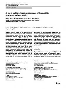
2.2 Data link applications An alternative system called Data-Link is currently studied in most country. This system tries to solve the bandwidth problem by providing another communication channel between pilots and controllers. This system implies a modification of both the controller workstation and the pilot board. In this paper we will mainly focus on the air traffic control workstation. The problem in modifying these systems is that the level of reliability of the air traffic control applications as to be guaranteed at the same level as before. This level is very high as no air plane accident has ever occurred due to an error made by air traffic control. Several systems offering data link facilities are currently studied at CENA. An example of a data-link application (called Druides) under development at the CENA is shown on Figure 1.
This Figure presents a hard copy of the screen of Druide. Only part of the application is shown here. The screen can be split in 3 different regions: • the light grey part which correspond to the sector handled by the controller. In this sector, white line represent plane routes. On these routes planes are represented by a succession of white dots the first one being the actual position of the plane and the smaller ones the previous positions. Along with these dots information concerning the flight are displayed: the callsign of the flight, its speed, its heading and the next beacon it is supposed to fly over. • the dark grey part which represent all the outside of the controlled sector, • the open menu used by the controller for entering information. This menu is a pop-up menu that appears when the user clicks on the label of a flight. When it pops-up, the menu is split in two parts: • On the left side the direct command menu (no parameter is needed) which offers three commands, SEND and ABORT (for sending or cancelling the current data-link command) and VOICE for asking the pilots to call the controller using the radio. • On the right side of the menu the user can select one of five commands which need parameters: FREQ (for asking the pilot to switch form one radio frequency to another one), CFL (for changing the Current Flight Level of the plane), SPEED (for changing the speed), HEAD (for changing the heading of the plane) and BEACON (for changing the route of the plane i.e. the next beacon it has to fly over). Each time the controller selects one of these commands, another pop-up menu appears (see Figure 1) that allows for entering the parameter of the command. By pressing CNC (cancel) this pop-up menu is closed, by selecting a value, the parameter is set, and by clicking on the arrows, the values presented are scrolled.
Figure 1 : The ATC System Allowing Data Link Commands
2.3 The requirements A set of requirements that have to be fulfilled by the data link applications are expressed below in ACTL (Emerson 88) for those that imply temporal constraints, or using set theory for the other ones. Requirements can be classified in two categories : high-level requirements related to the very semantics of air-traffic control, and lower level ones, related to interaction techniques. • A control order is only received by one plane • Any request sent by a controller will be received at some time by a pilot. • A control order is sent to only one plane (only one plane can be selected at a time) • For each control order, only one information is sent • All control orders finish by either Abort or Send • It is not possible to build several orders at a time
Requirement 1 : Each request sent by a controller to a plane p is received by that plane Let Planes be the set of planes in a sector, let DLRequest be the set of possible data-link requests sent by a controller, let Vrequest be the set of all the possible voice requests (requests sent using radio) : ∀ p ∈ Planes, ∀ req ∈ DLRequest, AG[send(req,p)]AFtrue For all the possible futures (A operator) and for all the states (G operator), if the controller send a request req to a plane p then for all the possible futures (A operator) in the sequence of states (F operator) there will be a state in which the plane p will receive the request req. The angled brackets means that it is mandatory that it exists such a state. Requirement 2 : A data-link request sent by a controller to a plane p is received by only that plane ∀ p,p' ∈ Planes, ∀ req ∈ DLRequest,
AG[send(req,p)]AG[not(receive(req,p')]true Requirement 3 : A voice request sent to a plane p is received by all the planes in the sector ∀ p ∈ Planes, ∀ req ∈ VRequest, send (p, req) ⇒ ∀ p' ∈ Planes, receive (p', req) Requirement 4 : It is not possible to build several orders at a time ∀ p ∈ Planes, ∀ req, req' ∈ DLRequest, AF[start_send(req,p)]A[True{not(start_send(req',p) }U(end_send(req,p)}true] which means that if a request order has been started then it will not be possible to start another one until (U operator) the first one has been terminated.
Supervision of traffic
Radar watching*
|||
First contact with the plane*
Communication
|||
>> Annotate strip Answer pilot >> Give information ||| Dialogue *
|||
Shoot plane
Annotate strip *
[] Give information
Ask information
Give parameter Identify plane
>> Ask parameter
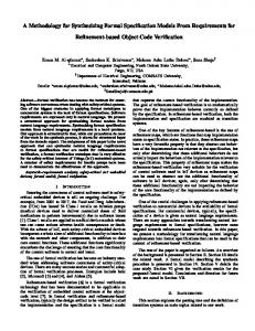
Figure 2 Hierarchical description of tasks
3. TASK MODELLING This section is devoted to describe the tasks that have to be managed by the controller. We will mainly focus on the ones that are addressed by data link applications but of course they can potentially be done in parallel with all the others tasks of the controller (cooperation with the other controller, resolution of conflicts, take over, ...). The fundamental tasks are first analysed in an abstract and hierarchical way, and are later detailed with an operational formalism that allows to express more precisely concerns such as data-flows and synchronisations.
3.2 Tasks in the current system We have chosen high-level Petri nets as the formalism for detailed task modelling. This formalism features a graphical notation which makes the models more readable, but more importantly it also has a high degree of formality, which makes possible the proof of properties on the task models.
3.2.1 The Petri net formalism System
Controller
Pilot
New Com munication
First Contact
3.1 Tasks in the application domain We use ConcurTaskTree to specify the tasks: it is a diagrammatic notation which shows the task hierarchy and indicates the temporal relationships among tasks at the same level. T1 ||| T2 indicates that the tasks can be performed in concurrent way, T1 >> T2 means that when T1 is terminated then T2 is activated, TX* indicates that task TX is repeatable (when it terminates it can be executed again until another task will disable it), T1 [> T2 indicates that when the first action of the T2 task occurs then T1 is disabled. The following task model describes how planes are managed by the air traffic control. When a plane enters a given sector, its pilot has to contact the controller for that sector. The controller then manages the flying over his/her sector, and terminates by « shooting » the plane, i.e. transferring it to the next sector.
New Plane on Radar
Handled Planes
Radar View
Com munication
Plane out of Sc ope
New Strip
Strip board
Shoot Plane
Com munication band
Discar d Str ip
Figure 3 Top-level Petri net task model When modelling with Petri nets (Murata 89), a system is described in terms of state variables (called places, depicted as ellipses) and by state-changing operators (called transitions, depicted as rectangles), connected by annotated arcs. The state of the system is
Give P aram eter
Identify Plane
As k for P aram eter
Com m unic ation
Identify Plane
As k for Inform ation
< p>
F is rt Co ntac t
Ans w er Pilot
The task model shows that the handling of a plane by a controller is initiated by the pilot of a plane, who makes a phone call to the controller. A precise sequence of actions has then to be undertaken to confirm this contact (Figure 4, Macro-transition « First Contact »). The controller is then involved in several communication with all the planes that he/she handles, and this task involves watching the radar view and manipulating the strips on the strip board (Figure 5, Macro-transition « Communication »). It is important to note that, in this version of the system, the communication band is shared by all the pilots : any message emitted is listened to by all the other pilots flying over a given sector. The inconveniences brought by this shared resource have been highlighted in the first section of this paper. However, this can also be considered as a valuable feature of the system : it happens that pilots point out misunderstandings in a conversation between the controller and another plane.
G ive Inform ation
given by the marking of the net, which is a distribution of tokens in the net’s places. In coloured Petri nets, the tokens assume values from predefined types, or colours. State changes result from the firing of transitions, yielding a new distribution of tokens. Transition firing involves two steps: (1) tokens are removed from input places and their values bound to variables specified on the input arcs, and (2) new tokens are deposited in the output places with values determined by emission rules attached to output arcs. A transition is enabled to fire when (1) all of its input places contain tokens, and (2) the value of those tokens satisfy the (optional) Boolean constraints attached to the input arcs. Figure 3 shows the Petri net description of the user’s task in the current system, before the introduction of data-link features. This task model is presented in an « organisational » style, where the different operations to be performed are classified according to the actor who holds the responsibility for this action. We distinguish between operations to be performed by the system itself (detecting new planes or printing out new paper strips on the controller’s desk), by the pilot (initiating a new communication with the controller) and by the controller. The task model of Figure 3 is hierarchical, the shaded transitions being actually macro-transitions that can be further refined by more detailed nets.
Annotate S trip
< p> G ive Inform ation < p>
< p>
Figure 5 : Macro-transition « Communication »
Ann otate Strip
Figure 4 : Macro-transition « first contact » Figure 4 shows such a macro-transition, which details the operation « first contact » as a mere sequence of simpler subtasks. The main focus of this model is the controller’s task. The operations performed by the other actors are only present to describe the data and the control flow between the different entities involved in the system.
The subtask « Communication », illustrated in Figure 5, is the most complex in this model : there is a choice between two lower-level tasks (« Give Information » and « Ask for Information ») while the subtask « Annotate Script » can be performed concurrently.
3.3 Tasks including data link features The introduction of data-link features in the systems allows to migrate to the system’s responsibility several operations that were previously of the controller’s
responsibility, thus diminishing the controller’s workload. A particularly difficult operation for the controller in the initial system is the matching of plane identifiers (provided through voice communication with pilots) with planes that are displayed on the radar screen and with the related paper strip on the strip board. This operation actually gives rise to numerous identification errors in the conversations between controllers and pilots. This problem can be noticed in the task model in Figure 3, as the macro-transition « Communication » requires the same variable
(standing for Plane) coming from three different places (Radar view, Strip board and Handled planes). In the Petri net model that we use, this is akin to the semi-unification mechanism of languages like prolog, and the presence of such a configuration in a task model indicates a significant workload for the user. We have already presented a method for accurately calculating the workload of the users using performance evaluation techniques available in the Petri net theory (Palanque 96).
4. SYSTEM MODELLING 4.1 Interaction Technique Modelling This section is devoted to the modelling of the interaction techniques for entering data-link commands. In Figure 7 we can see the coarse grain of dialogue for this interaction. Abo rt DL
< p> < p>
Unselec ted P lan es
S elec ted P lanes
Selec t P lane
DLMenu
< p>
Op tion s to S elec t
< p> Voic e Request
< p>
Bu ild D ata Lin k Req uest
Figure 7 : Coarse grain of interaction Options to Select
Fr equenc y Abort Request
System New Plane on Radar
Controller
Pilot
Radar View
First Contact
Canc el
Select Fr equenc y Plane out of Scope
Handled Planes
Shoot Plane
New Str ip
Canc el
List of Frequencies
Fr equenc y Selected
Give Param eter Disc ard Strip
Update Str ip
Strip board
Select Fr equenc y
Waiting for Wilc o
Send Request
Abort Request
Selected Planes
Str ip to be updated
Wilc o
Figure 6 Task model with data-link features The new task model in Figure 6 clearly shows that the introduction of data-link features allows for a significant reduction of the task model’s complexity. Actually, macro-transitions are not needed in this diagram, and the whole task model fits in a single schema.
Figure 8: Subnet for « Build Data-Link Request » Figure 8 presents how a specific data link command can be built by the controller. This model corresponds to the refinement of the greyed out transition in Figure 7. This kind of interaction is the same for the five different data link commands. For this reason only the one corresponding to the "Change frequency" command is presented.
4.2 Verification of the requirements A necessary step in the life cycle is to prove that the requirements presented in section 4.1. In this section we show how to check on the models that the system fulfils. This kind of verification techniques are based on the computation of marking graph and the verification of the temporal formula on this marking graph. Proving Temporal Logic formulas over Petri net based specifications has already been studied (Jancar 90), and most of the results can be reused for our purposes. For space reasons, the detailed proofs are not shown here, but we have dedicated a paper to the topic of verification of specifications (Palanque 95).
5. CONCLUSION We have shown in this paper that formal models and techniques can provide fruitful insights at various stages of the development life cycle of safety critical interactive applications. All the models (requirements, task models, coarse grain of dialogue and low-level interaction) have been expressed using mathematically based formalisms. It is of first importance that, at every stage, the models provided are precise enough in order to express behaviour without ambiguity. Besides, this will provide designers with mathematical tools that make it possible to reason about the specification. The formalisms that we have selected offer crossverification mechanisms that ensure consistency of the various models. A reproach often addressed to the supporters of formal methods in HCI is the lack of real life examples supporting the feasibility of their use. Even though only a small excerpt of the case study is presented here we hope that this example demonstrates the scalability of our approach to life-size applications.
ACKNOWLEDGEMENTS The authors would like to thanks Stéphane Chatty and Muriel Preux as well the DRUIDES team at CENA, namely: Sylvie Courteix, Stéphane Marché, Arthur Mustieles, Luc Novalès, and Sophie Tahmassebi that provided us with all the information about the data-link application. The authors would like to
acknowledge the Italian CNR and the French CNRS (by the way of the GDR-PRC-CHM) which partially supported this work under the cooperation project n° 3226. Last but not least we would like to thanks anonymous reviewer for helping us in improving the final version of the paper.
REFERENCES (Emerson 88) Emerson E.A., Srinivasan J. Branching Time Temporal Logic, in LNCS 354 p.122-172, Springer-Verlag 1988. (Hall 96) A.Hall, "Using Formal Methods to Develop an ATC Information System", IEEE Software, pp.66-76, March 1996. (Jancar 90) Jancar P. Decidability of a temporal logic problem for Petri nets. Journal of Theoretical Computer Science, vol. 74, pp. 71-93, 1990. (Johnson 95) C.Johnson, "The Application of Petri Nets to Represent and Reason About Human Factors Problems During Accident Analyses, Proceedings DSV-IS’95, pp. 93-112, Springer Verlag. (Mackenzie 94) D.MacKenzie, "Computer-related accidental death: an empirical exploration", Science and Public Policy, 21, , August, pp.233-248. (Murata 89) T.Murata, "Petri net Properties, analysis and applications". Proceedings of the IEEE (77), 4, 1989, pp.541, 580. (Palanque 1996), Palanque P & Bastide R. Performance evaluation as a tool for evaluating the formal design of user interface. Proceedings of the IEEE CESA’96 conference, IEEE Press 1996, pp. 235-245. (Palanque 95), Palanque P & Bastide R. Verification of an interactive software by analysis of its formal specification. Proceeding of Interact'95 conference Chapman et Hall. pp. 191-196. (Palanque 96) Palanque P., Paterno' F., Bastide R., Mezzanotte M. Towards an Integrated Proposal for Interactive Systems design based on TLIM and MICO. Proceedings of DSV-IS'96, Springer Verlag 1996. (Paterno 95) F.Paterno', M.Mezzanotte, "Formal Analysis of User and System Interactions in the CERD Case Study", Proceedings of EHCI'95, Chapman & Hall Publisher, 1995.