Introducing Formal Specification Methods in Industrial Practice ∗ Luciano Baresi, Alessandro Orso, and Mauro Pezz` e Dipartimento di Elettronica e Informazione Politecnico di Milano Piazza Leonardo da Vinci, 32 20133 Milano, Italia +39 2 2399 3400 baresi|orso|
[email protected] ABSTRACT Formal specification methods are not often applied in industrial projects, despite their advantages and the maturity of theories and tools. The scarce familiarity of practitioners with formal notations and the difficulties of their use are main causes of the limited success of formal specification methods. Approaches based on the use of popular front-end notations formally defined with mappings on formal models can solve practical problems. However the absence of flexibility of the mappings proposed so far limits the applicability of such approaches to the few environments that match exactly these solutions. This paper presents an original solution based on formalisms to define mappings from front-end notations to formal models. The proposed framework works with different front-end notations and formal models and supports mappings of analysis results obtained on the formal model to the front-end notation chosen by the practitioners. The approach described in this paper has been validated in industrial environments using pilot applications. The paper presents some of the industrial results obtained so far and ongoing experimentations. Keywords Specification notations, Formal methods, CASE tools. INTRODUCTION Presently, most software is developed using informal specification methods. Ambiguities, inconsistencies, and limited analysis capabilities of such methods badly affect the final products, that often do not correspond to the initial specifications and present unexpected fail∗ This work has been partially sponsored by the ESPRIT project EP8593 IDERS.
ures. Formal specification methods can solve many problems, guaranteeing non ambiguity and supporting powerful analysis capabilities. Formal specification methods have been successfully applied to peculiar projects [12, 18], but their impact on industrial practice is still limited. Formal methods succeed when they do not require additional specific skills [33], or when software development involves experts of formal methods [9]. In the first case, formal methods are easily accessible to the experts of the application domains, and they can be applied without a specific background. Most analysis capabilities of programming languages, such as type checking or data flow analysis, are examples of successful formal methods applicable without specific skills. In the second case, the application of formal methods can imply big changes in the development teams and in the costs of the projects. Theorem provers, such as PVS [28], are examples of formal methods that are not easily accessible to experts of the application domains, but require experts of formal methods, and thus are seldom applied in industrial practice. Recently, many researchers investigated solutions based on dual language approaches, that conjugate informal, widely used front-end notations with rigorous, formal models. These works propose mappings from specifications given in terms of front-end notations to formal models [11, 10, 35]. In this way, the experts of the application domains can benefit from the use of formal methods interacting with familiar notations. All solutions propose a fixed mapping from front-end notations to formal kernel models, that determine fixed interpretations of ambiguities. Unfortunately, the same notation is often used with different interpretations in different organizations and sometimes even within the same organization or development team. Fixed, rigorous interpretations can meet the needs of a specific application domain, but they fail to provide more general solutions. This paper proposes an original technique that introduces a flexible dual language approach, based on a formalism for defining mappings from popular front-end specification notations to formal models. Different in-
terpretations of the same front-end notation or different front-end notations can be supported by simply changing rules in the proposed formalism. The flexibility of the approach allows different interpretations of the same notation to coexist. Customization rules are validated by checking the correctness of executions of test specifications. The underlying formalism guarantees the consistency of the generated formal model. The same framework can be used in different organizations and teams without forcing a unique interpretation, but simply by adding or by modifying suitable rules. Thus, a tool supporting the approach would promote the use of formal methods even in those application domains that do not have a market wide enough to support the development of ad-hoc tools. The flexibility achieved with the solution proposed in this paper solves many problems that still limit the industrial application of dual language approaches. The next section briefly recalls the related works, discussing the relation with the results presented in this paper. The following sections present the theoretical foundation of the approach based on graph grammar theory, illustrate the main issues related to the design of a supporting tool, and outline the main results obtained by the application of a prototype to pilot industrial projects. The conclusions recall the main results achieved so far. RELATED WORK The work presented in this paper cuts across several research areas: method integration, multi-views systems, meta-environments, application generators, and visual languages. The variety and the broadness of the works in these areas make a detailed analysis difficult and space consuming. Here, we only summarize the key points with respect to our work. Method integration that attempts at making graphical informal notations benefit from formal models has been the starting point of our work. Many approaches combine features of two or more methodologies. As illustrated in the introduction, these approaches lack flexibility. They all refer to a fix semantics of the graphical informal notation, that hardly meets the many interpretations that can be found in different application domains. Some of them do not define a complete automatic translation, but present a set of guidelines to manually derive a formal model from an informal one. Not all of them define a reverse mapping to show the results of executing and analyzing the formal model in terms of the graphical notation, thus limiting the advantages of a dual language approach. Multi-views systems overcome the limitation of environments based on specific single notations. PRISMA [24] allows users to employ different formalisms to capture
multiple views of a system, and it maintains a coherent and integrated description of the models. In [39, 26], multi-paradigm specifications are obtained by composing partial specifications in different languages. Users do not have to tailor their specifications to the language, but the language is chosen according to the specific aspects to model. CDIF [7] proposes a common format for integrating heterogeneous information: a meta-metamodel, similar to an Entity-Relation-Attribute model, to describe the unified underlying data model. These and other works emphasize the need for different notations to specify large complex systems. They go beyond the approach we are proposing in this paper by making the underlying representation integrating multiple, and possibly overlapping, representations of a system. However, these proposals concentrate on the static view of a system, but not on its dynamics. Simulation and animation of produced models are not addressed, and analysis capabilities are limited to static checks. Meta-environments are emerging as means for constructing software production environments, that better cope with user needs and expectations. The taxonomy proposed in [20] identifies customizable environments, that offer a core set of functionalities with capabilities for augmenting/tailoring them according to the specific requests. Customizable text editors are introduced in [25, 31]. These editors are customized by defining the grammars of the languages which they edit and the semantic checks. Flexible environments that support definitions of objects to be manipulated are described in [5, 38, 37]. Users can define objects and tools to operate on them, or the type of information which will be used during the predefined development process. Customizable editors for manipulating graphbased software specifications are introduced in [29, 36]. They support multiple-layout of graphic information and they allow the specifications of functionalities of user interfaces through languages for describing the syntax of icons and their static semantics. None of them is designed to check the dynamic semantics of the produced models. Application generators propose an original way to cope with multiple user needs, by letting users build their own environment. Application generators translate specifications of applications into implementations, acting as application compilers. These techniques have been successfully applied to data processing, and parsing [15], but they are less successful in systems programming. Multi-level representations associated with declarative mappings between levels have been used to support the editing of visual languages. [22] describes a general framework for translating pictorial data into an abstract representation and vice-versa. The mapping rules, ex-
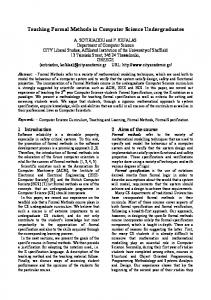
pressed in Prolog, define element translations, but they do not provide means to check the correctness of produced representations. [1] and [34] introduce graphoriented solutions very similar to our approach. In [1], a visual programming language is represented on four levels: physical layout, pictorial structure, abstract structure, and representation of the meaning. It shows how graph grammars can be employed to maintain the representations up-to-date with each other. More attention is paid to higher levels; the representation of the semantics is solved by associating textual meaning to each production. The graph grammar presented throughout the paper merges the different levels into a single very complex graph. An alternative way to express the correspondences between two graphs, keeping the graphs separated, is presented in [34]. The work illustrates, under a theoretical viewpoint, the use of three graph grammars to describe both the languages of the two graphs and the relations between them. THE APPROACH This section introduces a flexible framework for defining the syntax of graphical front-end notations, for expressing their operational semantics with a formal (kernel) model, and for presenting the results on the formal model in terms of the graphical front-end notation. The approach addresses operational graphical specification notations, e.g., data flow diagrams, control diagrams, Statecharts. The semantics can be given in terms of operational formal “graphical” models, e.g., Petri nets, communicating finite state machines, task interaction graphs. We focus on the definition of abstract syntax, semantics, and visualization of results. Concrete syntax and internal representations of models are inherited from current CASE technology, which is not substituted, but enforced by our approach. The definition of abstract syntax and semantics of graphical notations requires the ability of designing rules for graphical languages. The framework proposed in this paper refers to the well known theory of graph grammars ([23]). A brief summary of the few concepts of graph grammar theory required to understand this paper is given in Appendix. Two graph grammars, called Abstract Syntax Graph Grammar (ASGG) and Semantic Graph Grammar (SGG), define the abstract syntax and the semantics of a graphical front-end notation. Each ASGG production corresponds to a SGG production. User modifications of the front-end notation are captured by means of ASGG productions; the associated SGG productions describe how to automatically update the formal kernel model. This approach is shortly illustrated in Figure 1, that presents a subset of the graph grammars that give semantics to data flow diagrams (DFDs) in terms of high-level timed Petri nets (HLTPNs [13]).
Production addTransformation adds a functional transformation (node 2) to the DFD model, identified by the marker (node 1). The SGG production defines the subnet corresponding to a functional transformation. A transformation is modeled by two transitions (nodes 4 and 6) to start and to end the execution connected through a place (node 2), that indicates the status of the transformation. All the new elements are linked to the diagram maker by b-edges indicating that they belong to the diagram. Notice that arcs of both the graph and the Petri net correspond to nodes of the GG production, linked to the source and destination nodes by GG edges. Production addStore adds a store (node 2), whose HLTPN representation is a marked place (node 2) The two remaining rules show how to connect a transformation to a store or to another transformation. ASGG productions simply add a flow between the two elements. The SGG production of rule connectStoreTransformation connects the place corresponding to the store (node 3) to the start transition of the transformation (node 2) and adds a new place (node 4). The added place stores the value acquired from the data store during the execution of the transformation. The SGG production of rule connectTransformationTransformation connects the end transition of the first transformation (node 1) to the start transition of the second one (node 2) by adding a new place (node 4) and connects the start and the end transition of the target transformation (nodes 2 and 3) by a new place (node 5). This added place stores the input value from the added DFD flow (node 3) during the execution of the transformation. Often graphical notations are textually annotated. Textual annotations must be suitably translated into the operational formal model. In the example of Figure 1, functional transformations are annotated with textual specifications that describe the functions performed on the connected flows, and data stores are annotated with their initial values. GG attributes convert textual annotations into predicates and actions associated with transitions and into values associated with tokens. The rules defined in Figure 1 set all the textual attributes needed to build a complete formal model. When the right side of an assignment is left unspecified, it means that the value is not computed, but it has to be provided from the outside. In the example of Figure 1 attribute id of new elements of the DFD is given by the front-end CASE tool, name and the other specific attributes (spec and value) are given by users. Only attribute type is set directly by the rule. SGG productions can refer to attributes of the nodes of the corresponding ASGG production by enclosing the expression between two “@”. For example, attribute name of nodes 2, 4, and 6 of the SGG production of rule addTransformation are derived from the value of attribute name of node 2 of the
addTransformation
addStore
ASGG
SGG
ASGG
4
tf
3
T 1
2
M
1
b
S
2
b b
2
M
M
b
1
1
M 1
3
2
b
tp
M
tf
1
SGG
1
M
M
b
M
1
5 tt
6
2.id= 2.name= 2.type="transformation" 2.spec=
[email protected]@Exe 2.type="transformation"
[email protected]@Start 4.type="startTransformation" 4.predicate="TRUE"
[email protected]@End 6.type="endTransformation" 6.predicate="TRUE" 6.action=convert(@2.spec@)
2.id= 2.name= 2.type="store" 2.value=
connectStoreTransformation
connectTransformationTransformation
ASGG
SGG
ASGG
[email protected]@ 2.type="store"
[email protected]@
SGG 1 tf
1
S
3
S
1 3
T
2
T
tf
3
tf
7 2
T 2
tf
tf
6
3
T
2
7 2
3
8
ttr
2
1 4
4
1
tf
ttr tp
2
tp
1
T
1
tt
tt tf tp
T 5
2
tf
tf
5 1
6
tt
9 tt
3
3.id= 3.name= 3.type="flow"
2.action=4.name "=" 3.name ";" 2.action
[email protected]@"V" 4.type="currVal"
2.action=5.name "=" 4.name ";" 2.action
[email protected]@ 4.type="flow"
[email protected]@"V" 5.type="currVal"
3.id= 3.name= 3.type="flow"
Figure 1: ASGG and SGG productions for data flow diagrams. corresponding ASGG production. Figure 2 illustrates by an example how the graph grammar productions of Figure 1 are applied to build a complete semantic model. The excerpt of the concrete model is annotated with the initial value 28, for the data store and with the pseudo-code defining the function performed by the transformation. The internal abstract representation of the model is built by applying rules addStore and addTransformation in any order and then rule connectStoreTransformation. Automatically, the corresponding HLTPN is defined. The token of place S1 gets the value from store S1. The predicate of transition T1Start is set by rule addTransformation, while its action is set by rule connectStoreTransformation. Place names are used within actions as variables referring to a token in the place. Similarly, both the predicate and the action of transition T1End1 are set by rule addTransformation. Kernel formal models can be analyzed using several techniques, e.g., execution, reachability analysis, model checking. Users of front-end notations may ignore the 1 Function
convert adds suffix V to the names of the input flows in the specification associated with a transformation.
28
Predicate: TRUE Action: f1V=S1
28 S1
S1 f1
T1Start f1V
T1
T1Exe
f2 f2 = (f1/10) * 10 if ((f1 mod 10) > 4) f2 = f2 + 10;
T1End
f2
Predicate: TRUE Action: f2 = (f1V/10) * 10 if ((f1V mod 10) > 4) f2 = f2 + 10;
Figure 2: The construction of the HLTPN semantics of an annotated data flow diagram obtained by applying the ASGG and SGG productions of Figure 1.
details of the kernel model, thus analysis results must be suitably presented in terms of the chosen front-end notation. In this paper, we focus on visualizing model executions. The problem of visualizing analysis results is discussed in [2]. Executions are characterized by sequences of events, e.g., transition firings, that can be shown to the experts of the application domains by animating their models through sequences of graphical events. To
if (getType(tranId) == "startTransformation") then beginAE foreach placeS (getType(placeS) == "store") in preset begin beginE entityId = getAbsId(placeS); eventType = "readStore"; endE foreach elmF (getType(elmF) == "flow") in outputs(getAbsId(placeS)) if (target(elmF) == getAbsId(tranId)) beginE entityId = elmF; eventType = "crossFlow"; eventPars = [("value", compute(placeS))]; endE end foreach placeF (getType(placeF) == "flow") in preset beginE entityId = getAbsId(placeF); eventType = "readFlow"; eventPars = [("value", compute(placeF))]; endE beginE entityId = getAbsId(tranId); eventType = "startTransformation"; eventPars = [("status", "executing")]; endE endAE
Figure 3: The animation rule for the kernel event corresponding to the firing of a transition of type startTransformation for the data flow diagram of Figure 1. define the animation mechanism, we need few basic concepts: kernel, abstract and concrete events2 . A kernel event is generated in the formal model, e.g., a transition firing. Each kernel event is associated with a type that identify the kind of the action, an identifier that identifies the subject of the action on the formal model, and one or more elements, that describe the changes on the status. An abstract event is an animation event at an abstract level. It is composed of a set of single events, one for each front-end notation element that is affected by the animation. An abstract event comprises an object identifier, an event type, and, if needed, one or more parameters. An abstract event acts as a container to relate all the front-end notation animations which spring from a kernel event. A concrete event is a graphical action shown at the front-end notation level. Animation is defined as a translation of kernel events into concrete events, through abstract events. The intermediate abstract layer supports adaptability and allows easy reuse of animation rules. The relation between abstract and kernel events is defined by means of animation rules, that are formally de2A
similar hierarchy is required also to visualize analysis results: kernel, abstract and concrete visualizations [2].
fined by a textual grammar, whose BNF is reported in Appendix. Each type of kernel event is associated with an animation rule, that describes the triggered abstract event. As an example, Figure 3 shows the animation rule for the kernel event represented by the firing of a transition of type startTransformation for the data flow diagram of Figure 1. The rule looks for all the places of type store in the preset of the fired transition (tranId). These places correspond to the data stores entering the transformation that is about to execute. An event readStore is defined for each identified store. Among all the flows leaving each store, the rule defines an event crossFlow for the one whose target is the transformation linked to tranId. This event requires as parameter the value the animation will display on the flow. All the places of type flow in the preset of tranId identify all the flows connecting other transformations with the transformation corresponding to the fired transition. For each flow, there is an event readFlow whose parameter is the read value. Finally, we define a startTransformation event for the transformation which is about to execute. 28
S1
S1
= S1 entityId eventType = "readStore"
f1 T1
T1Start
T1Exe
f1v
S1 = f1 entityId eventType = "crossFlow" eventPars [("value", 28)]
28
T1
f1
S1
S1 = T1 entityId eventType = "startTransformation" eventPars = [("status", "executing")]
T1Start
28 T1Exe
f1 T1
f1v
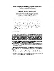
Figure 4: The animation of the excerpt of Figure 2 using the animation rule of Figure 3. Figure 4 illustrates the application of the animation rule of Figure 3 on the DFD of Figure 2. The firing of transition T1Start triggers the abstract event startTransformation, that removes the datum from the input data store S1 (readStore event), “moves” the datum on flow f1 (crossFlow event), and blacken the functional transformation T1 to indicate that it is executing (startTransformation event). TOOL SUPPORT A toolset based on the approach introduced in this paper copes with different representation levels and map-
pings among them. Figure 5 illustrates the three main layers, that correspond to the three main sets of functionalities illustrated in the previous section: kernel, abstract, and concrete layers. The concrete layer supports interactions with users and deals with the concrete syntax of the chosen front-end notation. The abstract layer checks the abstract syntax of user specifications; it produces the formal models corresponding to user specifications according to SGG productions, and it transforms execution and analysis results into the syntax chosen by users. The kernel layer executes and analyzes automatically defined formal models. In this section, we functionally decompose each layer. Concrete Layer The concrete layer comprises an end user interface module (Front End Notation Editor) and a C/A Converter. Front End Notation Editor The front end notation editor deals with concrete syntax aspects: it creates and stores specifications in the chosen graphical language, animates them and it shows the results of execution and analysis of the corresponding formal models. A CASE tool can be used as front end notation editor if it provides animation and visualization capabilities, e.g., it must be possible to flash or blink elements. Additionally, it must allow interactions with external components, e.g., through shared files. Most commercial CASE tools provide such functionalities. As illustrated in the next section, we successfully experimented with Software through Pictures [19] (hereafter StP) and ObjectMaker [21]. Concrete Layer
Front End Notation Editor
C/A Converter
Abstract Layer Customization Editor
ory Reposit
Customization Rules Interpreter
into calls to ASGG productions. To make this transformation the C/A converter must be aware of both the format of the used CASE tool and of the policy chosen to invoke ASGG productions. A first, and straightforward, way of selecting ASGG productions consists in capturing and translating each single user’s action. This approach precludes the reuse of existing specifications and requires an ASGG production for almost all the actions that users can do. Parsing user specification diagrams overcomes the drawbacks of the “event-driven” approach, but it can result in being very expensive (the membership problem is known to be NP-complete [32]). An alternative solution consists in imposing a (partial) order over the set of productions to guide the generation process. The C/A converter applies productions according to the order defined so far. Since the underlying representation of all the diagrams, we are able to deal with, is a graph, a “reasonable” sequence firstly creates the nodes, and then connects them. If textual annotations are required, they can be added either while creating the abstract syntax object they refer to or by specific productions to be applied after the creation of the objects. This way of applying ASGG productions does not penalize performances and limits the number of necessary productions. A single production can translate a group of user actions. Moreover productions for deleting elements are not strictly necessary. They are mandatory following the “event-driven” approach. According to the “generative” approach, deleting productions are not used for translating a model from scratch, while they are required to incrementally translate the changes performed on a previously defined model. Messages from the CRI to the front-end notation editor correspond to invocation of the animation (visualization) capabilities of the user interface. Sequences of messages describe animations of user specifications corresponding to executions of the formal model or visualizations of analysis results.
Figure 5: The overall structure of an environment supporting a customizable dual language approach.
Abstract Layer The abstract layer comprises a Customization Rules Interpreter (CRI), a Repository, and a Customization Editor. The abstract layer represents the core of the system, that compounds existing CASE tools used at the concrete level, with existing formal tools used at the kernel level. The abstract layer supervises the translation of user specifications from the concrete to the kernel model and of kernel events and results into abstract events and visualizations respectively.
C/A Converter The C/A converter governs data exchange between the chosen user interface and the Customization Rule Interpreter (CRI). Exchange of messages is bidirectional. Messages from the concrete to the abstract layer are invocations of ASGG productions. In this case, the C/A converter translates a specification
Customization Rules Interpreter Roughly speaking, the customization rules interpreter is a two-way translator: it transforms user specifications into formal models, sequences of kernel events into sequences of abstract events, and analysis results into abstract visualizations. To perform the former translation the
Kernel Layer
A/K Converter
Kernel
customization rules interpreter acts as an interpreter of graph grammars. It executes ASGG productions and the corresponding SGG productions according to the application sequences defined by the concrete layer. In the latter translations, events and results from the kernel are transformed into abstract events and visualizations, respectively, by interpreting proper textual rules. Repository The repository stores the customization rules. It deals with different sets of rules, according to the front end notations supported at the concrete level and according to the semantics they are given. Customization Editor The customization editor supports the definition of new customization rules. We successfully experimented with both an emacs-based textual customization editor and an xfig-based graphical customization editor. Kernel Layer The kernel layer comprises a Kernel and a A/K Converter. Kernel The kernel performs execution and analysis of formal models. It can be based on existing tools. As illustrated in the next section, we successfully experimented with different kernels based on high-level timed Petri nets (HLTPNs). The choice of Petri nets is due to the background of the authors and to the availability of supporting tools. A/K Converter The A/K converter translates messages from kernel format to CRI format and viceversa. Messages from CRI to the kernel are invocations of kernel functionalities to add the elements defined by applying SGG productions to the formal model. Messages from kernel to CRI propagate events and visualizations (analysis results) of the formal model. VALIDATION The validation of the approach proposed in this paper followed three orthogonal directions: validation of the theoretical approach, by defining mappings between different end-user notations and formal languages; development of a prototype of the customization rules interpreter, that works with different front-end notations, CASE tools, and kernels; industrial validation by using the customization rules interpreter in pilot industrial projects with independent users. Validation of the Theoretical Approach So far, the approach has been used to give HLTPN semantics to the following front-end notations: FIFO Nets (an extension to Petri nets with places of type FIFO), Statecharts [16], Hatley & Pirbhai requirements definition notation [17], a design notation for SA/RT [3], and LEMMA (Language for an Easy Medical Models Analysis) [6], an ad-hoc notation for the modeling of medical diagnostic processes. User models have been
Notation FIFO Nets LEMMA Statecharts Design Notation Hatley&Pirbhai
# Rules 20 30 40 50 60
Table 1: Complexity of defined notations.
annotated using C++ and VDM-SL. The number of GG rules needed for the definition of each notation in terms of HLTPNs is summarized in Table 1. The number of rules reflects the complexity of the front-end notation in terms of elements and their connectivity. Hereafter we will refer to the customization rules interpreter customized for a specific notation X as CRI(X). Development of a Prototype A prototype of the customization rules interpreter has been developed and has been integrated in different environments. For the sake of the shortness, in the following only the most relevant environments will be shown. The CRI(Hatley&Pirbhai) has been integrated with two commercial editors (StP and ObjectMaker) and with two different HLTPN based kernels (Cabernet [30]) and IDERS [8]). StP and ObjectMaker have been customized using the built-in customization capabilities provided by these two tools: the QRL language [19] and the ObjectMaker Extl language respectively. The customization allows us to catch all relevant end-user actions performed within the editor (creation/deletion of objects, hierarchical decomposition, setting of values and so on). Alternatively, the translation can be performed off-line, by analyzing the user model stored in the repository, flattening it, and generating all the necessary syntactical directives to build the abstract and then the kernel model from scratch. The integration with the two kernels has been performed by building two middlewares (one for each kernel) that use the APIs provided by the two kernels and interfacing the mapping rules interpreter to such middlewares. The CRI(SA/RT Design Notation) has been integrated with the IDERS Kernel by means of the already built middleware, using StP customized accordingly as frontend notation editor. Again, it is possible to perform both on-line and off-line translation. The CRI(LEMMA) has been integrated with the Cabernet Kernel by means of the already built middleware, using an ad-hoc editor written in Tcl/Tk [27] as frontend notation editor. Table 2 summarizes the different configurations of the prototype experimented so far.
Notation Hatley&Pirbhai Hatley&Pirbhai Design Notation LEMMA
Kernel Annotations Front-End Editor Cabernet C++ ObjectMaker IDERS VDM-SL StP IDERS VDM-SL StP Cabernet None Ad-Hoc
Table 2: Configurations of the prototype.
Industrial Validation The CRI(Hatley&Pirbhai) has been used by Alenia3 as part of the ESPRIT project IDERS. The application chosen for validating the approach is the RPCM (Reply Processor and Channel Management), a safety critical real-time system being part of a secondary radar management apparatus, in charge of controlling air traffic in a wide range. RPCM has been developed by a team of experts of Alenia using structured analysis as supported by StP, and it has been validated on HLTPNs automatically produced by the prototype. The RPCM data model is composed of 49 nodes on 4 hierarchical levels, and of 13 process specifications, while the RPCM control model comprises 12 states on 5 State Transition diagrams. The corresponding Petri Net comprises 93 places, 564 arcs and 88 transitions. The use of “formal” structured analysis made Alenia pay greater attention to many project details, otherwise neglected, while the off-line validation allowed them to discover uncatched errors and inaccuraces. The CRI(LEMMA) has been validated at Policlinico Umberto I (IV Clinica Semeiotica) in Rome by modeling a protocol to diagnose the colo-rectal cancer. CONCLUSIONS This paper presented a technique to give formal semantics to graphical specification notations by defining a mapping on a formal operational model. Unlike previous works, that give fixed semantics, the technique proposed in this paper is fully customizable, thus allowing semantics to be adapted to the specific needs of the application domains. New notations can be formally defined by simply giving different sets of rules. The well understood theory of graph grammars that provides the basis for the proposed technique guarantees the generality of the approach that has been validated by means of a significant set of specification notations. Environments based on the proposed technique can easily relay on different CASE tools and formal kernels, 3 Alenia is a Company of Finmeccanica, Italy major international high-tech manufacturing group, active in the aerospace, defense, energy, transportation, and automation markets.
thus allowing the reuse of existing technology and reducing the impact of its introduction in industrial practice. The technique has been successfully validated on real projects using a prototype which is currently used by an independent industrial team for full validation. Our experience with industrial partners shows that the flexibility and the user-friendliness of the proposed approach can make formal techniques easily accessible in environments with little background in formal methods, but large experience in specific application domains. Otherwise these experts would hardly be able to access formal specification techniques. Our short-term research plans include the assessment of the technology by defining formal semantics for new notations, and by experimenting with new formal (kernel) methods. We are looking with particular interest at object oriented specification notations to be customized by means of Petri nets and other formal models, e.g., finite state machines or process algebras. Our mid-term research plans include the study of modularization of graph grammars to allow automatic reuse of subsets of rules across family of notations, and the investigation of new animation and verification techniques based on the feedback of the users. In the long-term, we are looking at merging discrete execution capabilities with continuous animation features to address the emerging area of hybrid systems. REFERENCES [1] M. Andries, G. Engels, and J. Rekers. How to Represent a Visual Program? In Proceedings of International Workshop on Theory of Visual Languages, June 1996. [2] L. Baresi. Formal Customization of Graphical Notations. PhD thesis, Dipartimento di Elettronica e Informazione – Politecnico di Milano, 1997. in Italian. [3] L. Baresi, V. Braberman, M. Felder, M. Pezz`e, and F. Pieniazek. A Practical Approach to Formal Design of Real-Time Systems. In Proceedings of the 1996 IEEE International Conference on Systems, Man and Cybernetics, pages 1014–1019, October 1996. [4] H. Bunke. Programmed Graph Grammars. In V. Claus, H. Ehrig, and G. Rozenberg, editors, Graph-Grammars and Their Application to Computer Science and Biology, volume 73 of Lecture Notes in Computer Science, pages 155–166. Springer-Verlag, 1979. [5] S.C. Choi and W. Scacchi. SOFTMAN: An Environment for Forward and Reverse Computer-Aided Software Engineering. Information and Software Technology, 33(9):664–674, Nov. 1991. [6] F. Denna and A. Re. Specifica e Verifica Formale di Processi Clinici. Master’s thesis, Politecnico di Milano, Milano (Italy), June 1996. (in italian). [7] EIA/CDIF. CDIF Family of Standards, 1994. [8] M. Felder, C. Ghezzi, and M. Pezz`e. High-Level Timed Petri Nets as a Kernel for Executable Specifications. Journal of Real-Time Systems, 5(2/3):249–272, May 1993.
[9] K. Finney. Mathematical Notation in Formal Specification: Too Difficult for the Masses? IEEE Transactions on Software Engineering, 9(6):733–744, 1996. [10] J. Fischer and E. Dimitrov. Verification of SDL Protocol Specifications Using Extended Petri Nets. In Proceedings of the Workshop on Petri Nets and Protocols of the 16th International Conference on Application and Theory of Petri Nets, pages 1–12, 1995. [11] R.B. France. Semantically Extended Data Flow Diagrams: A Formal Specification Tool. IEEE Transactions on Software Engineering, 18(4):329–346, 1992. [12] S. Gerhart, D. Craigen, and T. Ralston. Experience with Formal Methods in Critical Systems. IEEE Software, 11(1):21–28, Jan. 1994. [13] C. Ghezzi, D. Mandrioli, S. Morasca, and M. Pezz`e. A Unified High-Level Petri Net Model For Time-Critical Systems. IEEE Transactions on Software Engineering, 17(2):160–172, Feb. 1991. [14] H. G¨ ottler. Attribute Graph Grammars for Graphics. In H. Ehrig, M. Nagl, and G. Rozenberg, editors, Graph Grammars and Their Application to Computer Science, volume 153 of Lecture Notes in Computer Science, pages 130–142. Springer-Verlag, 1983. [15] R.W. Gray, V.P. Heuring, S.P. Levi, A.M. Sloane, and W.M. Waite. Eli: A Complete, Flexible Compiler Construction System. Communications of the ACM, 35:121–131, Feb. 1992. [16] D. Harel. Statecharts: A Visual Formalism for Complex Systems. Science of Computer Programming, (8), 1987. [17] D.J. Hatley and I.A. Pirbhai. Strategies for Real-Time System Specification. Dorset House, New York, 1987. [18] M. Hinchey and J. Bowen. Applications of Formal Methods. Pretice-Hall International Series in Computer Science. Prentice-Hall, 1995. [19] Interactive Development Environments. Structure Environment: Using the StP/SE Editors, Feb. 1994. Release 5. [20] A.S. Karrer and W. Scacchi. Meta-Environments for Software Production. Technical report, University of Southern California, Atrium Laboratory, Dec. 1994. [21] Mark V Systems. ObjectMaker User’s Guide, 1994. version 3. [22] S. Matsuoka, S. Takahashi, T. Kanada, and A. Yonezawa. A General Framework for Bidirectional Translation between Abstract and Pictorial Data. ACM Transactions on Information Systems, 10(4):408–437, 1992. [23] M. Nagl. A Tutorial and Bibliographical Survey on Graph Grammars. In V. Claus, H. Ehrig, and G. Rozenberg, editors, Graph Grammars and their Application to Computer Science and Biology, volume 73 of Lecture Notes in Computer Science, pages 70–126. Springer-Verlag, 1979. [24] C. Niskier, T. Maibaum, and D. Schwabe. A Look Through PRISMA: Towards Pluralistic KnowledgeBased Environments. In Proceedings of the fifth International Workshop on Software Specification and Design, May 1989. [25] D. Notkin. The GANDALF Project. Journal of Systems and Software, 5(5):91–105, May 1985.
[26] B. Nuseibeh, J. Kramer, and A. Finkelstein. A Framework for Expressing the Relationships Between Multiple Views in Requirements Specification. IEEE Transactions on Software Engineering, Oct. 1994. [27] J.K. Ousterhout. TCL and the TK Toolkit. Professional Computing Series. Addison Wesley, 1993. [28] S. Owre, J. Rushby, N. Shankar, and F. Von Henke. Formal Verification for Fault-Tolerant Architectures: Prolegomena to the Design of PVS. IEEE Transactions on Software Engineering, 21(2), Feb. 1995. [29] F.N. Paulish and W. Tichy. EDGE: An Extenible Graph Editor. Software Practice and Experience, 20(S1), June 1991. [30] M. Pezz`e. Cabernet:A Customizable Environment for the Specification and Analysis of Real-Time Systems. Technical report, Dipartimento di Elettronica e Informazione, Politecnico di Milano, Italy, May 1994. [31] T. Reps and T. Teitelbaum. The Synthesizer Generator. In ACM SIGSOFT/SIGPLAN Software Engineering Symposium on Practical Software Development Environments, Apr. 1984. [32] G. Rozenberg and E. Welzl. Boundary NLC Graph Grammars — Basic Definitions, Normal Forms, and Complexity. Information and Control, 69:136–167, 1986. [33] H. Saiedian. An Invitation to Formal Methods. IEEE Computer, pages 16–30, Apr. 1996. [34] A. Sch¨ urr. Specification of Graph Translators with Triple Graph Grammars. In Proceedings of the 20th International Workshop on Graph-Theoretic Concepts in Computer Science, volume 904 of Lecture Notes in Computer Science, pages 151–163. Springer-Verlag, 1994. [35] L. Shi and P. Nixon. An Improved Translation of SA/RT Specification Model to High-Level Timed Petri Nets. In Proceedings of Formal Methods Europe 96, volume 1051 of Lecture Notes in Computer Science, pages 518–537. Spriger-Verlag, Mar. 1996. [36] K. Smolander, P. Marttiin, K. Lyytinen, and V.P. Tahvanainen. MetaEdit - A Flexible Graphical Environment for Methodology Modelling. Advanced Information Systems Engineering, pages 168–193, 1991. [37] A. van Lamsweerde, B. Delcourt, E. Delor, M.C. Schayes, and R. Champagne. Generic Lifecycle Support in the ALMA Environment. IEEE Transactions on Software Engineering, 14(6):720–741, June 1988. [38] Y. Yamamoto. An Approach to the Generation of Software Life-Cycle Support Systems. PhD thesis, University of Michigan, 1981. [39] P. Zave and M. Jackson. Where Do Operations Come From? A Multiparadigm Specification Technique. IEEE Transactions on Software Engineering, 22(7):508–528, 1996.
GRAPH GRAMMARS A detailed and complete overview of all the graph grammar models proposed in more than 25 years of theoretical research would be out of the scope of this section. This appendix only briefly introduces the few concepts required to understand the paper.
A graph grammar (GG) is a set of productions. A GG production consists of three parts: a graph which is to be substituted, a graph which is to be inserted, and a set of embedding rules, that define how the graph to be inserted has to be connected to the graph on which the production is applied (host graph). A GG production can be given a graphical representation, as shown in Figure 6. The Y [14] identifies the three components of a production: graphs (1) and (2) correspond to the graphs to be substituted and inserted, respectively, and graph (3) together with the connections of graph (3) with graphs (1) and (2) represent the embedding rules. Nodes and edges of GG productions are labeled. In the example of Figure 6, labels are A, B, C, D, and E for nodes, and f , g, and h for edges. Embedding rules are identified by chains. A chain is a un-directed path connecting exactly one node of graph (1), to one or more nodes of graph (3), and to exactly one node of graph (2). In the GG production of Figure 6, we can identify two f h h h chains: A ← E ← B and A ← E → A. In the example f h of Figure 6, the first chain (A ← E ← B) states that there will be an f -edge from the newly created B-node to all the E-nodes that were connected to the A-node of the replaced graph by an incoming h-edge. The sech h ond chain (A ← E → A) indicates that all the E-nodes linked to the A-node of the removed graph by a h-edge must be connected to the newly created A-node by a h-edge. In this case the two chains identify the same set of E-nodes. E
h
f
(3) h
B
f
D
f
A
A
g
C
(1)
(2)
Figure 6: The Y notation A GG production is applied to a host graph by matching graph (1) against a subgraph of the host graph, the so called redex, by replacing the redex with a copy of graph (2), and by connecting the added subgraph to the host graph according to the embedding rules (chains). If there are more occurrences of the left-hand side graph in the host graph, then one is chosen non-deterministically. Figure 7 illustrates an application of the GG production of Figure 6. In this paper we use an extended formalism to improve performances and modeling power. The basic model has been extended by adding explicit context, textual
E
E
f g
D
B
h
h
f
f
A h
A g
f
C
E E
Figure 7: A sample application of the GG production of Figure 6. attributes, and programmability ([4]). In Figure 6, the A-node belongs to both graphs (1) and (2). This node, removed by the application of the proh
h
duction is re-inserted. The chain (A ← E → A) is necessary to re-establish part of the lost connections (h-edges). Unchanged nodes, like the A-node in the example, define the context of the production. In the extended model used in this paper the context is identified by associating nodes with an identifier; the nodes with the same identifier in graphs (1) and (2) define the context. When a GG production is applied, these nodes and their connectivity remain untouched. The nodes that belong to graph (1) only are deleted, while the nodes that are in graph (2) only are added to the host graph. In this paper node identifiers are natural numbers, as shown in Figure 8. The model presented so far well describes the graphical structure of an application, but it is not suited to represent textual information. Textual information are attached to the elements of a production by means of attributes [14]. Productions are augmented with a set of rules to specify how these attributes are set or modified when the production is applied. Figure 8 shows a simple example of a production with attributes. The rules listed at the bottom of the production state that the newly created C-node (identified by the number 3) is associated with three attributes: name, cordx, and cordy. The first attribute is assigned a constant value, while the other two are determined starting from the values of the attributes of node 1. GG productions are applied atomically. Splitting productions may alter the consistency of the host graph. This constraint forces users to specify huge graph modifications within a single production, compromising the readability of the production itself. Moreover, within a single production users cannot address a dynamically defined number of objects. The graphs to be replaced and introduced statically determine nodes and arcs that are created and deleted by applying a production. These problems are solve by using programmed graph grammars [4], that allow sets of productions to be applied in
E
10. attributeV alue = constV alue|computedV alue 11. computedV alue = ‘compute(’Kentity‘);’
h
(3)
12. entity = Kentity|Aentity 13. condP = ‘getType(’Kentity‘) ==’ Ktype| ‘getType(’Aentity‘) ==’ elementT ype
D 2
f
1
A
14. set = Kset|Aset
A 1 g
15. Kset = ‘preset’|‘postset’ 3
(1)
C
(2) 3.name = "C"; 3.coordx = 1.coordx + 10; 3.coordy = 1.coordy;
Figure 8: An extended GG production. a given order. ANIMATION RULES This appendix presents the BNF defining the animation rules instantiated for a HLTPN kernel. Each transition in the kernel model is assigned a “type”. Types code played in giving semantics to front-end notation elements. A rule defines how to build an abstract event from any kernel event of a given type. At run-time, the mapping rules interpreter uses these rules to create an abstract event for each transition firing. Animation rules are defined according to the following grammar. The grammar comprises both notationindependent and notation-dependent productions. The first group defines the format of the rules4 : 1. abstractEventRule = ‘if (’condT ‘) then’ ‘beginAE’ (statement)+ ‘endAE’ 2. condT = ‘getType(’tranId‘) ==’ Ktype 3. statement = eventRule| ‘if (’condT P ‘) then’ statementList [‘else’ statementList ‘foreach’ entity [ ‘(’condP ‘)’] ‘in’ set statementList 4. statementList = statement| ‘begin’ statement (statement)+ ‘end’ 5. eventRule = ‘beginE’ ‘entityId =’ Aentity‘;’ eventT ype [eventP ars] ‘endE’ 6. condT P = Aentity ‘==’ Aentity| ‘eval(’Kentity‘)’ 7. eventT ype = ‘eventType =’ EventN ame‘;’ 8. eventP ars = ‘eventPars = [’attributeList‘];’ 9. attributeList = (‘(’attributeN ame‘,’ attributeV alue‘)’)+ 4 the
conventions used in drawing the grammar are: | select one of; [] optional; ()+ iteration from 1 to n).
16. Aset = ‘inputs(’Aentity‘)’|‘outputs(’Aentity‘)’ 17. Kentity = intV ar 18. Aentity = ‘getAbsId(’Kentity‘)’| ‘target(’Aentity‘)’| ‘source(’Aentity‘)’| intV ar
Variable tranId represents the identifier of the fired transition returned by the kernel. The term intV ar represents an integer variable. Predefined functions have the following meaning: getType(entity) returns the type associated with an entity. getAbsId(Kentity) returns the identifier of the abstract object corresponding to Kentity. preset/postset return the preset/postset of the fired transition. source/target(Aentity) return the single element connected to Aentity by an incoming/outgoing flow. inputs/outputs(Aentity) return the set of elements connected to Aentity by incoming/outgoing flows. compute(Kentity) returns a value computed on Kentity. eval(Kentity) returns a boolean evaluated on Kentity. The last two functions are “virtual” functions. For each place type in the kernel model, users have to provide the actual implementation. The second set of productions specifies the actual symbols on which the rules will work. For instance, the notation sketched in Figure 1 requires the following definitions: 19. Ktype = "startTransformation" | "endTransformation" | "transformation" | "store"| "flow" | "currVal" 20. attributeN ame = "status" | "value" 21. eventN ame = "startTransformation" | "readTerminator" | "endTransformation" | "writeTerminator" | "readStore" | "writeStore" | "readFlow" | "writeFlow" | "crossFlow" 22. elementT ype = "transformation" | "store" | "flow" 23. constV alue = "idle" | "executing"
The last step in customizing animation requires each abstract eventN ame to be linked to a concrete action. These actions are defined according to the CASE tool used as front-end notation editor. They must take into account both CASE tool capabilities and users’ needs. This decoupling lets the same grammar define different concrete animation. The abstract definitions remain untouched, while users are free to change the associated concrete actions.