Formal Specifications of Software Design Methods J. Artur Serrano Departamento de Electrónica e Telecomunicações, University of Aveiro, Aveiro, Portugal Email:
[email protected]
Abstract A new approach to the formal specification of software design methods, such as ER or State Transition Diagrams, is presented. A formal language based on semantic constraints is used to specify those methods. An example using the UML’s Activity Diagrams is given which illustrates the proposed approach. The aim of this work is to provide a bridge across the gap between the formal methods and the less formal ones used in software design.
1
Introduction
There is a large gap between what formal methods can do for software engineering and what they are used for at the present. A large number of software engineers avoids using formal methods and tools because of the generalised idea that they are not that easy to use. In fact, Martin Fowler, a well-known consultant in the area of object technology, says: “formal methods are hard to understand and manipulate, often harder to deal with than programming languages” [1]. Another drawback usually pointed out to some formal notations is that they cannot be executed. For these reasons, formal methods are left aside by many software engineers. With the work already done in the formal 1 methods community we believe it is possible to bridge that gap mentioned above and do a bit more that just “not be rigorous (…) follow the traditional methods path and appeal to your intuition” (also in [1]). Most software design methods, such as OMT [2] or UML [3], are not formally specified and their notation appeals to intuition rather than to a formal definition. Our thesis is that a simple formal approach could be taken to specify such software design methods and that way, guarantee that they are in fact rigorous. This is what I try to show here. t A novel formal language - VC - was developed with the aim of providing formal tools to non-experts in formalisms, which is the case of many software developers. The language has already been well accepted by software engineers [4]. This paper looks at the question of how a software design method can be formally specified. t VC is used to show how formal constraints can be an answer to that question. An example of this approach is given for UML’s Activity Diagrams. The fact that this paper has been submitted to a formal methods workshop has the aim of letting our approach to be known outside the software engineering community and also of allowing the author to become aware of some formalists opinions on it and to get some feedback on how it can be improved.
2
Related Work
One of the few attempts to formalise software systems prototyping, i.e. the automatic generation of complete systems from formal specifications, has been presented in [5]. Hekmatpour describes a system for rapid software prototyping named EPROS. This system tries to solve the problems associated with the conventional ‘life cycle’ model of software development. The following aspects of software prototyping are covered by EPROS: functionality, which expresses what the software system must do and is based on execution of specifications written in META-IV, the formal specification notation of VDM; and the human-computer interface, based on a textual representation of State Transition Diagrams. The system uses an executable formal specification language, EPROL, which combines the two notations mentioned above, i.e. functionality and dialogue; the design notation; and also the implementation notation. The design notation is to be used in the refinement and modularization of the software system under construction, which includes features such as abstract data types, functions and a formalism called ‘cluster’ (addressed below). The implementation notation is based on a hybrid of C and Pascal.
1
Althoug this paper has just one author, the work described here results from the involvement of several people. For that reason, I have chosen to use in some situations the plural form in the writing of this paper.
IWFM, 1999
1
Formal Specifications of Software Design Methods The ‘cluster’ formalism is a form of modularization based upon the generalisation of procedural abstraction. It is used when functions and procedures are inadequate. Using the ‘cluster’ mechanism, the programmer can extend the already existent facilities provided by the EPROS system. A goal of the use of ‘clusters’ is software reuse. The systems development is performed in an iterative fashion (from abstract to concrete). The result of each iteration is an executable EPROL specification of the system that can be converted into a working prototype. When the user is fully satisfied with the exhibited behaviour of the system the dialogue specification and the functional specification can be integrated and the final prototype is obtained. How does this approach relates to our work? The EPROS architecture features both an EPROL interpreter and a compiler that generates LISP code. Using the interpreter it is possible to browse both dialogue and functional specifications. The final products, implemented in LISP, are then executed by a module called ‘executor’. It is not clear to what extent intermediate prototypes can be tested by the user. According to the paper: ‘the executor has the role of executing finished products’. Also, only finished products in LISP may access the window manager and the I/O subsystem through the ‘executor’ module. So, apparently, with intermediate prototypes it is not possible to generate output or interact with the system. In our approach there is no concept of specifications’ refinement; however, they can be written incrementally and for each obtained specification a working prototype can be readily and automatically generated, which provides the user with the full set of graphical and interactive features included in the development environment. t Unlike VC , the domain of application of EPROL is not restricted. For the specification formalism to be able to describe any possible application it has to be very generic and include a vast and rich set of concepts. The result is t a necessarily complex specification language (the syntax has 83 rules, against 53 of VC - see Appendix). Moreover, in order to be generic it must be able to support any software mechanism. The ‘cluster’ formalism can be used to program these mechanisms, but this is a time consuming task. This work is more concerned with the formal aspects of the approach than with its usability. To us, both the formalisation and the language usability are important, i.e. the way it can be used to achieve concise, consistent and unambiguous specifications that can also be parsed by a compiler. In [6] a language for the specification of software design methods, called PSN (Picture Specification Notation), is described. PSN is to be used within a prototype of a software tool building system. A graphic editor that is driven by PSN specifications of software design methods in a way that guarantees syntactic correctness is included in that system. We claim in Section 3 that grammars are not the best approach to specify software design methods; this work backs our claim. After some experimentation with grammars, the authors of that work encountered a number of difficulties. It was difficult to elaborate a suitable grammar for that purpose and even more difficult to build a parser for it. They claim that a grammar notation is also hard to understand, use and verify. The notion of production rules is not enough to express all concepts of software design methods. Also, a grammar cannot ensure total syntactic correctness, as an example the authors say that it cannot prevent circularity of processes in a DFD. A grammar-based formalism is not appropriate for handling incomplete diagrams. In the PSN based approach the graphical notation ‘G’ of a software design method is seen as having three components: lexical, which denotes the symbols used in G; syntactic, the rules governing the combination of symbols in the production of a diagram; and semantic, “which denotes the meaning attributed to each syntactically valid picture in G”. The paper does not explain how the semantic information is used in the system. In our approach we separate the aspects related to the visual appearance from the semantic ones. We believe this is a neater structure in what it provides a clear separation from the geometrical relationships rules which are valid for all notations, such as those for overlapping objects, for the connection of shapes or the creation of labels. PSN specifies the rules of a notation, i.e. the syntax according to their definition. The alphabet (symbols) is defined separately using an interactive editor. We use a similar approach: the symbols (shapes and line styles) are t defined using a graphical objects’ editor while the rules (constraints) are specified in VC language. In spite of being a very expressive language, PSN was not designed for the purpose of automatic code generation. We have an expressive formal specification language, which is also used in the automatic generation of executable code. The generation of usable interactive design editors that truly support the editing task using the semantics of the underlying technique is a main goal in our approach. This was not pursued in Hekmatpour and Woodman’s work. The metamodelling community is doing a lot of interesting work. A good overview of concepts and systems for metamodelling is presented in [7]. Blaha also addresses metamodelling in an introductory way in [8]. The OMT [2] object model notation is used to obtain a number of restricted metamodels of some widely known software design methods. A study on CASE tool integration performed over a number of large organisations in the United States is presented in [9]. The study revealed that the majority of organisations either use particular CASE tools as and when necessary with no tool integration, or use clusters of CASE tools integrated to support a part of the process. More developed integration technology, such as framework-based integration or multiple integrated CASE tool clusters are not common. A language for the definition of a variety of software design methods called MDL (Model Definition IWFM, 1999
2
Formal Specifications of Software Design Methods Language) is proposed in [10]. An interesting aspect of this work is the possibility of the automatic generation of a Schema Definition Language (SDL) from the corresponding MDL definition (unfortunately not presented in detail in the paper). A formal framework using a new construct called ‘ViewPoints’ is given in [11]; it is used in the development of systems requiring multiple methods. Two research groups have been producing work which includes aspects that are particularly related to this paper. The first one is a Dutch group. Hofstede presents a formal language that is able to express constraints [12]. The language is called LISA-D (Language for Information Structure and Access Descriptions) which is a formal extension of RIDL (Reference and IDea Language). LISA-D is based on the conceptual modelling technique PSM (Predicate Set Model), an extension of PM (Predicate Model) which in turn is a formalisation of NIAM. The feasibility of completely flexible CASE shells is discussed in [13] (a CASE shell is defined in the paper as a method independent CASE tool, which may be instantiated with a specific method). The term ‘flexibility’ is used to refer to the extent to which users are able to adapt a tool to their working style. Three orthogonal dimensions are identified in a CASE shell repository: method level versus application level; process versus product (also referred to as “way of working versus way of modelling” [14]); and conceptual versus graphical knowledge. The first dimension, also referred to as ‘types versus instances’, is not considered to create a hard problem. The ‘process’ part of the second dimension relates to the tasks to be performed during the modelling work. Tasks are classified according to their size: large tasks, for instance “perform the Business Area Analysis” within the Information Engineering method; and minor tasks, e.g. “add an external entity to a diagram” in the DFD modelling technique. It is claimed by the authors that most state-of-the-art meta-modelling techniques do not address the way of working; although a number of CASE shells have already been produced and even commercialised they do not support the modelling process. The ‘product’ part shows the structure and relationships between the information modelling products. Obtained models must generally satisfy complex rules imposed by the software design methods. To capture such rules a powerful constraint modelling technique is required. For that purpose the approach uses both graphical representation of constraints in PSM, e.g. total role or uniqueness constraints, and the constraint modelling language LISA-D for constraints that cannot be expressed graphically (which are in fact the majority, as they declare). The third dimension relates conceptual to graphical knowledge. As stated by the authors, this is “particularly important for CASE shells”. This specifies “how models appear on the screen and how actions can be performed on these represented models”. The second working group is a Finnish team. The work of the team led by Lyytinen is done in the context of the development of a CASE shell called MetaEdit+ [15]. A CASE shell is defined as a tool that can be customised by users to support their own preferred methodologies [15]. In [17], the weak support given by CASE tools to the users’ native methods and methodologies is mentioned. Although the approach taken in MetaEdit+ is somewhat different from ours, it has a common goal with our work in that they both support high-level specification of software design methods using an easy to use specification language. MetaEdit+ was implemented in VisualWorks 2.0 (Parc Place). The tool is multi-user and multi-platform. It allows multiple representations of the same conceptual object (for instance, graphical, matrix or text) and even different graphical representations of the same object in any given representation paradigm. MetaEdit+ is based on the GOPRR (Graph Object Property Role Relationship) data model (it is in fact a meta-metamodel for it is used to obtain metamodels of methods). GOPRR offers a graphical notation with which models can be constructed. Note that this is also the approach we take in this paper, therefore it can be considered as a metamodelling approach. The process of method adaptation is described in [18]. During this process a formal model of the method is derived. A tri-dimensional metamodelling framework is proposed (equivalent to the one used by Hofstede in [13]). The three dimensions are: type/instance, conceptual/representational and statics/dynamics. However the third dimension is not explored in the paper. A feature of GOPRR that is particularly related to our work, is the possibility of attaching integrity checking rules to properties, in addition to normal type rules. Although it is possible to express some integrity rules (or constraints as we call them), they must be very simple ones, as for example “a string property must be a dotted sequence of numbers”. This rule forbids combinations such as ‘Fred’ or ‘2.’. More complex integrity rules, such as t the ones we can specify in VC , cannot be expressed in GOPRR. The literature indicates that a desired direction for the work in MetaEdit+ is “to increase the capabilities to describe integrity constraints within and between method t specifications”. We believe VC has provided a positive contribution to this topic. Why have we not used graph grammars (GG) in our approach? The RWTH group in Aachen, Germany, has been working with GGs for more than 15 years. Their experience in the area of software engineering stems from two projects: IPSEN [19] and PROGRES [20]. The latest developments of the PROGRES based system seem to indicate that GGs are moving in the right direction. A specification obtained with the PROGRES language can be executed by an interpreter that shows the effects of the graph rewriting operations. The specification is checked for IWFM, 1999
3
Formal Specifications of Software Design Methods consistency and a stand-alone prototype can be automatically generated from it. The PROGRES compiler is able to produce “easy-to-read” C or Modula-2 code from which a final implementation can be derived. “The language PROGRES, its tools and the GG engineering methodology are a first step [...] to establish graph rewriting as a new specification and programming paradigm”. It is also declared that “we have to admit that currently available tools and techniques are far from being as mature as (for instance) logic-oriented or functional centered tools and techniques”. As it is said in [21] “Will the future bring the breakthrough? In my opinion, there is a fair chance.”. We believe more evidence is still needed. Our work has some of its roots in ECLIPSE [22]. ECLIPSE is a software development system designed to t support several methods. Ray Welland, one of VC authors, was involved in the construction of such system. A specification language, called GDL (Graphical Description Language), is used in the system to describe software t design methods. We believe that VC has reached a much higher level of usability and expressiveness than GDL. Recently, a new working group [23] (pUML - ‘p’ stands for ‘precise’) has come together to discuss and research on developing UML (Unified Modelling Language) as a precise language. Their work consists on trying to find ways to formally specify the modelling techniques that are part of UML. This includes formalising the UML semantics. It is on this point that the group’s work is closest to our work. At the moment there are already some proposals on finding possible research directions, namely, the paper presented at UML'98 [24] points out the need for formally defining the semantics of UML.
3
The Problem - How to Express Formally a Software Design Method?
The scientific community is putting a lot of effort on finding new formal methods to express software design methods - see for instance [23]. Such formal methods, in order to be well accepted, must be easily applied by software engineers who might not be formalists. For that reason a very simple formal specification language has been developed. The other reason that led to the decision of creating a new language (instead of using 'Z' or 'VDM') was the fact that on of the objectives of this work was to be able to automatically generate software tools, used to support the design methods, from the obtained specifications; this was proven to be much easier with a new special purpose language than with a more general and complex formal specification language. The new language is called t VC and uses a set of constraints to express the semantics of a software design method. We designate these constraints by ‘semantic constraints’. They are assertions on the properties of a given method construct. Consider for example the ‘Entity’ construct on an Entity-Relationship (ER) diagram [25]; a possible semantic constraint would be: “all Entities on a diagram must be uniquely named”. Most formal methods are able to tackle a large spectrum of problems. For this reason they have to be very generic. To present this characteristic they become quite complex. Therefore, one possible way of reducing their t complexity is to reduce their application domain. We have applied this principle in the design of the VC language, i.e. it is able to express software design techniques quite well, but we can’t guarantee it can be used successfully to solve other problems. t The problem we tried to solve with VC was “how to specify the semantics of a software design method?”. That is, we wanted to be able to formally specify the meaning of all the constructs used in a given method. For instance, how can we formally express the ER example given above? Or the following semantics of a State 2 Transition Diagram (STD): “all final states in a diagram cannot have transitions leaving them” ? In a first approach to the problem we found two possible directions: using grammars or using constraints. As already disclosured we have decided to use constraints. Why have we made this choice? There are good reasons for this that we will now discuss.
3.1
Preserving semantic information
The problem of using grammars (both constraint-grammars and graph-grammars) to specify the semantics resides in the fact that the information expressed by a grammar is no longer tractable once code is generated from a specification. As a result of this, a generated editing tool is unable to give back to the user any semantic feedback (meaningful information) at editing time. Our approach of semantic constraints consists in encapsulating all the relevant constraints of a given method construct inside a specification object. During the automatic code generation this object’s identification is not lost. This way the semantic information is preserved from the specification to the final executable code across the generation process. Encapsulation can also be found in the paradigm of object-orientation. However, the most common object models (for instance, Eifel, Smalltalk or C++) do not provide support for the specification of semantics [26].
2
t
A full description and a VC specification of State Transition Diagrams are given in [27].
IWFM, 1999
4
Formal Specifications of Software Design Methods Semantics are normally embedded in the code of the object’s operations and are not explicitly included in the t language as in VC .
3.2. Inspecting specifications The main advantage of grammar specifications, over constraint based ones, is that they are easier to validate and to check for their completeness. However, producing a grammar specification can become a very tedious task and its complexity makes it accessible only to experts. Conversely, the concept of semantic constraint is easy to grasp and it provides a more intuitive way of producing specifications. A specification solely based on constraints is typically difficult to inspect. A possible solution to this problem t is to provide a demonstration mechanism for the specifications. In VC this can be achieved because we can automatically generate a working prototype for a given specification. This allows the user to visually inspect the results of the written specification.
4
Overview of VCt t
We have designed the VC specification language that is shortly presented below. It is not the purpose of this paper to t present the language in detail, for a more complete description of VC please refer to [30].
4.1
The VCt Specification Language
Diagram based software design methods such as DFD or ER are normally described in natural language. These t descriptions can be ambiguous and non-precise. VC is a formal specification language developed to express the semantics of software design methods and for that it uses a form of predicate logic with equality. The language is not a general purpose one. Because it has been intentionally designed to express the t semantics of software design methods, VC provides the necessary expressive power and leads to clearer and more readable specifications. Amongst the several language requirements which were used as a guide to its design we established that the specifications produced with the language must be parseable (computer-readable) and that code generation must be possible from a specification. The language should also be able to capture the variations of any of the more established software design methods in general use and application specific software design methods (usually being company defined). We want the user to be able to easily and quickly obtain a specification. That is only achievable if the language has a steep and short learning curve. The language users will be experts in software design methods (or at least have a fair knowledge of software modelling) but will not necessarily have any expertise in logics or formal notations. t In what follows, an overview of a VC specification is given.
4.2
A Very Simple Software Design Method
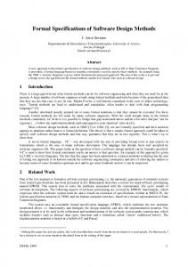
Just for exemplification purposes a very simple software design method was created. For this method a detailed nonformal description in natural language (English) will be presented. Afterwards, an explanation of how to obtain a t formal VC specification from this natural language description will be given. 4.2.1 The SimpleM SimpleM has only three constructs, the ‘State’, the ‘StartState’ and the ‘Event’. The graphical representations of the constructs are shown in Figure 1. -----
-----
State
-----
StartState
Event
label
Figure 1: SimpleM diagram constructs. The State is depicted by a rectangle and the StartState by an inverted triangle, both have a label with a name, which is unique amongst their instances; the Event is depicted by an arrow. IWFM, 1999
5
Formal Specifications of Software Design Methods A SimpleM diagram is structurally a connected graph in which the nodes and edges are graphically represented, respectively, by icons and connections. In the SimpleM the constructs represented by icons are the StartState and the State; the only construct represented by a connection is the Event. In a diagram there must be one and only one StartState; the other nodes (one or more) are States. The StartState can only be connected to States by outgoing Events. Any pair of States is connected at most by two Events, one in each direction. Loop Events, i.e. Events that connect a State to itself, are not allowed. The minimum diagram is composed by a StartState connected to a State by an outgoing Event. t
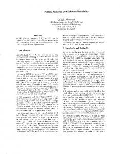
4.2.2 The VC Specification The first aspect of the SimpleM we must specify is its concept structure - the constructs and their properties. For this t purpose we will write the ‘Preamble’ section. In Figure 2 an excerpt of this VC specification is shown (the complete specification can be found in [27]). We must declare SIMPLEM as a cartesian product of the power sets of the 3 method constructs . Now, we divide the power sets into the ones that are represented by icons from the ones that are represented by connections and also declare extractors to isolate each one of them (sections B1 and B2) from the SIMPLEM. In section C we can declare auxiliary sets and extractors as expressions composed by those declared before. Section D is where the properties of the sets are expressed. The equality property is expressed to allow for comparisons during diagram traversal. Now, we must express the semantics already described informally above, using constraints formally written in a logic-based style. For this purpose we will write the ‘Semantic Constraints’ section. To make this presentation shorter, only a selection of the complete set of constraints is presented. The first constraint (C1) expresses the statement: “both StartState and State have a label with a name, which is unique amongst their instances”. Each constraint is specified by both a description in natural language and a corresponding sentence in predicate logic. The natural language description adds legibility to the specification and is used to give meaningful messages to the final user of the automatically generated tools (semantic feedback). ‘FORALL’ is the Universal Quantifier; it bounds the variables s1 and s2 ranging over the elements of the set AnyState, which is the union of StartState and State. s1 and s2 belong to the SimpleM set extracted by the function AnyStates. We are then saying that for all possible pairs of states in the diagram, for instance (s1, s2), if the name of s1 is equal to the name of s2, then s1 and s2 must be the same. C2 is a cardinality constraint. Finally, C5 expresses: “loop Events, i.e. Events that connect a State to itself, are not allowed”.
Because we need to translate VCt specifications into executable code, they must be used as input to a compiler. Our compiler is not able to parse mathematical symbols, such as ‘∀’ or ‘⇒’, therefore an alternative notation based in English lexemes is used: the words FORALL and IMPLIES replace, respectively, those two symbols. 3
IWFM, 1999
6
Formal Specifications of Software Design Methods
"SimpleM" SEMANTICS_SPECIFICATION PREAMBLE A.MT_MODEL BEGIN SIMPLEM == P StartState x P State x P Event simpleM : SIMPLEM END B.SET_EXTRACTORS_DECLARATIONS B1.ICONS BEGIN StartStates : SIMPLEM -> P StartState States : SIMPLEM -> P State END B2.CONNECTIONS BEGIN Events : SIMPLEM -> P Event END C.SETS_DEFINITIONS BEGIN AnyState == StartState U State AnyStates: SIMPLEM -> P AnyState END D.SET_PROPERTIES BEGIN StartState HAS_PROPERTIES name : StartState -> String equal : StartState x StartState -> Boolean […] Event HAS_PROPERTIES origin : Event -> AnyState destination : Event -> AnyState equal : Event x Event -> Boolean END SEMANTIC_CONSTRAINTS BEGIN C1: "Names are unique amongst States and StartState" FORALL s1, s2 : AnyState · s1, s2 BELONGING AnyStates(simpleM) IMPLIES ( name(s1) = name(s2) IMPLIES s1 = s2 ) C2: "There is exactly one StartState" CARDINALITYStartStates(simpleM) = 1 […] C5: "Each Event must connect a pair of different States or the StartState to a State - loop Events are not allowed" FORALL e : Event · e BELONGING Events(simpleM) IMPLIES ( NOT (origin(e) = destination(e)) ) […] END . t
Figure 2: An excerpt of the VC specification of SimpleM.
5
Some Formal Aspects of the VCt Language
The formal aspects are presented following the mathematical symbolism proposed by [29].
5.1
The Preamble Section
The Preamble expresses the software design method in terms of its constructs and declares all the sets that will be used in the specification. It comprises four sub-sections: the model, set extractors declarations, sets definitions and set properties. IWFM, 1999
7
Formal Specifications of Software Design Methods To specify the constructs we have employed elementary set theory. A generic software design method is expressed as the Cartesian product of the power sets of all its constructs: ‘SDMX = P Ct0 x P Ct1 x .. x P Ctn’ where: SDMX is an identifier, called the name of the software design method; Ct0 to Ctn are the constructs defined for the method. A variable of type SDMX is also declared to be used in the Semantic Constraints section. In the set extractors sub-section, power sets are divided into the ones that are represented by icons and the ones that are represented by connections. For each power set, an extractor is defined. An extractor is a triple , these being: mtd the software design method for which the extractor is declared, called the domain; ext an identifier, called the name of the extractor; cr a power set, called the range. So, for the software design method named ‘SDMX’ we have: ‘exti : SDMX → P Cti, i ∈ {0..n}’ No subtyping is allowed. However, it is possible to specify auxiliary sets in the sets definitions sub-section, as a union of other sets. For instance, for the SimpleM example the following set was defined: ‘AnyState == StartState U State’ Auxiliary sets can also be specified in extension, which is useful e.g. in the specification of pre-defined label strings. For instance cardinality labels for the ER method could be specified as: ‘Cardinality == {”1, 1”, “1,n”, “n, m”}’ Properties are declared in the set properties sub-section. Properties are the constrainable components of the method constructs. They are used in predicate logic statements of the constraints expressed in the Semantic Constraints Section. For instance, the following statement could be used in a constraint: ‘source(x) = destination(x)’ where: ‘x’ is an instance of a method construct; ‘source’ and ‘destination’ are properties of that construct. Set properties are defined as triples , where: cd is a set or a power set, called the domain; prop is an identifier, called the property name; tr can be a set, a pre-defined type (String, Natural or Boolean) or an auxiliary set, called the range. For example, an equality property for the construct ‘C’ would be specified as: ‘equal : C x C → Boolean’
5.2
The Semantic Constraints Section
A semantic constraint is a rule expressed as a sentence in a form of predicate logic with equality. The constraints can be divided into two groups: the instantiated predicate logic statements and the quantified predicate logic statements. An instantiated predicate logic statement is simply a constraint where the predicates have no variables (apart from the model variable); this means that the predicates are not quantified. An example of this kind of constraint is C2 defined for the SimpleM method. A quantified predicate logic statement is a constraint where the predicates use quantification of variables. This means that all the variables in the statement must be bound by quantifications. Quantifications can be existential or universal. Nested quantifications are allowed with any number of levels, and each quantification can either be an existential or a universal one. An existential quantification is specified as: ‘∃ x : T • x ∈S ∧ P(x)’ where: x is a variable bound by the existential quantification; T and S are sets such that S is a subset of T; P(x) denotes a predicate logic statement, i.e. any boolean expression with one or more predicates on the variable x. Likewise, a universal quantification is specified as: ‘∀ x : T • x ∈ S ⇒ P(x)’ Constraint C1 of SimpleM is a quantified predicate statement with a universal quantification. N-ary predicates, denoted by P(x1, x2, .. xn) with the variables x1, x2, .. xn ranging over the same or different sets, are also allowed. As for unary predicates, all the variables must be bound by quantifications. E.g. ∀ x : T • x ∈ S ⇒ ∃ y : Q • y ∈ R ∧ P(x, y). The language proved to be able to capture most of the constraints defined by the semantics of several standard software design methods covering static aspects of software (data modelling) and dynamic aspects (process modelling). However, we do not claim that the language is able to express all the semantics. For example, the semantics of diagram refinement, i.e. when a part of the diagram expands into a new diagram, cannot be expressed in t VC . This subject is covered in Section ‘Conclusions and Future Work’.
IWFM, 1999
8
Formal Specifications of Software Design Methods
6
A VCt Specification of Activity Diagrams t
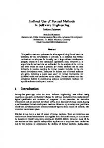
In this section I explain how the VC language can be used to specify the semantics of one of UML’s methods - the Activity Diagrams [1]. I will start by giving an overview of this method, then I include a natural language description t of it and finally I show its VC specification. An Activity Diagram is one of the methods included in UML (Unified Modelling Language). It is a useful tool to describe behaviour with a lot of parallel processing. Its structure is a connected graph in which the nodes are represented by icons and the edges by connections. An Activity Diagram includes the following constructs: Start, End, Activity, Decision Activity, Synchronization Bar and Trigger. Only the last construct is represented by a connection; the others are represented by icons. These constructs are shown in Figure 3. Guard [- - - - - -] -----Start
Activity
End
-----
Decision Activity
Synchronization Bar
Trigger
label
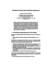
Figure 3: Activity Diagram constructs. The “Coffee/Cola” example of Figure 4 was taken from [1]. It models a situation of a person’s behaviour when having either a coffee or a can of cola to drink. The first activity is to find the beverage. If the person can find the coffee, he/she goes on to preparing one; if not, she/he tries to find a can of cola. In case the cola is found, the person drinks it; otherwise, no drink is taken. In what follows I will give a natural language description of the Activity diagrams method. If you find the description somewhat vague, dubious or unclear, that’s only natural - it is not a formal description. In the next t section I formalise this description using the VC language. I hope that one will be clearer.
IWFM, 1999
9
Formal Specifications of Software Design Methods Activity Start
Guard
Decision Activity
Person Find Beverage
Synchronization Bar
[no coffee]
[found coffee]
[no cola]
[found cola]
Trigger
Put Coffee in Filter
Add Water to Reservoir
Get Cups
Get Can of Cola
Put Filter in Machine
Turn on Machine
Brew Coffee
light goes out
End
Pour Coffee
Drink Beverage
Figure 4: Activity Diagram. A Start point cannot have incoming Triggers. An End point cannot have outgoing Triggers. A Trigger connects two different icons on the diagram, no self-loops are allowed. If an Activity has more than one outgoing Trigger, then each of these must have a Guard to allow for a decision. All Activities must be uniquely named. A Synchronization Bar must have at least one incoming Trigger and one outgoing Trigger. A Synchronization Bar must have at least three Triggers connected to it. A Decision Activity must have at least one incoming Trigger and two outgoing Triggers. All Triggers leaving from a Decision Activity must have a Guard. Any Trigger arriving at a Decision Activity must be connected to an Activity at its start. An Activity Diagram must include at least one Start point, one Trigger and one Activity. In this description I have left out the ‘decomposition’ feature of Activity diagrams. It is possible to expand an t Activity from a diagram into a new full diagram. VC is not able to express this feature. In Section ‘Conclusions and Future Work’ I will discuss this problem further. Note that only constraints have been specified; optional features are irrelevant. In fact they do not need to be included in the specification in order to assert the validity of a diagram. Also, graphical aspects are not described t because they are not covered by VC ; for simplification reasons the language leaves these details out intentionally. In what follows I include an excerpt of a specification for UML’s Activity Diagrams. IWFM, 1999
10
Formal Specifications of Software Design Methods
"Activity PREAMBLE
Diagrams" SEMANTICS_SPECIFICATION
A.MT_MODEL BEGIN AD == P Start x P End x P Activity x P DecisionActivity x P SinchronizationBar x P Trigger VAR ad : AD END B.SET_EXTRACTORS_DECLARATIONS B1.ICONS BEGIN Starts : AD -> P Start Ends : AD -> P End Activities : AD -> P Activity DecisionActivities: AD -> P DecisionActivity SinchronizationBars: AD -> P SinchronizationBar END B2.CONNECTIONS BEGIN Trigger : AD -> P Trigger END C.SETS_DEFINITIONS BEGIN ADicon == Start U End U Activity U DecisionActivity U SinchronizationBar ADicons : AD -> P ADicon END D.SET_PROPERTIES BEGIN […] Activity HAS_PROPERTIES name : Activity -> String equal : Activity x Activity -> Boolean […] Trigger HAS_PROPERTIES name : Trigger -> String source : Trigger ->ADicon destination : Trigger -> ADicon equal : Trigger x Trigger -> Boolean END SEMANTIC_CONSTRAINTS BEGIN C1: "A Start point cannot have incoming Triggers" FORALL s : Start · s BELONGING Starts(ad) IMPLIES NOT EXISTS t : Trigger · t BELONGING Triggers(ad) AND ( destination(t) = s ) […] C4: "If an Activity has more than one outgoing Trigger, then each of these must have a Guard to allow for a decision" NOT EXISTS t1, t2 : Trigger · t1, t2 BELONGING Triggers(ad) AND ( source(t1) = source(t2) AND (guard(t1) = "" OR guard(t2) = "") ) (* "" represents an empty string *) […]
IWFM, 1999
11
Formal Specifications of Software Design Methods C6: "A SynchronizationBar must have at least three Triggers connected to it" FORALL sb : SynchronizationBar · sb BELONGING SynchronizationBars(ad) IMPLIES EXISTS t1, t2, t3 : Trigger · t1, t2, t3 BELONGING Triggers(ad) AND ( source(t1) = sb OR destination(t1) = sb) AND source(t2) = sb OR destination (t2) = sb) AND source(t3) = sb OR destination (t3) = sb) ) […] END .
7
Conclusions and Future Work
I have presented here an approach for the specification of diagrammatic techniques used in software design methods. This is a novel approach in its use of semantic constraints that are formally specified. In order to allow for nont experts in formal methods to use the approach we have designed VC , a simple formal language that is based on a predicate logic. I gave a sample specification for Activity Diagrams, a modelling technique included in the Unified Modelling Language (UML). The main objective of this paper is to present our work to a community which is more on the formal methods side rather than on the software engineering side. The fact that the approach was developed mainly by software engineers helps in making it well accepted by people on that area, but if our goal to help bridging the gap between the two communities is to be achieved, then we must still get support from the formal methods people. The language is not yet in its final version. In fact, there is still missing a way of specifying refinement of objects in a diagram. This feature, also called ‘explosion’, is quite common in software design methods. An object in a diagram can be refined into a new diagram and a logical connection is always maintained between the two. This is possible even when the new diagram is expressed in a different notation of that used for the object. Our formalism t does not include a way of expressing this feature at the moment. We do intend to extend VC to make it able to capture this kind of object refinement. A part of our work that has not been addressed in this paper is what concerns the automatic generation of executable code. This will be presented in a future publication (hopefully) which is already in its final draft form. Some information on that subject can already be found in [31]. The code generation process is sufficiently generic to allow it to be applied to several target plattforms: a prototype using Napier88 [32] has already been implemented and a new experiment using Prolog is currently under way.
Appendix 1 VCt Syntax t
In this section a description in a simplified BNF of the VC language is given. The following conventions have been used: • • • • •
reserved words are in upper case, e.g. EXISTS. A number of keywords have several alternatives. A list of all keywords and available alternatives is shown in section 8.3; reserved characters are enclosed, e.g. “->” non-terminal symbols are in lower case, e.g. properties; terminal symbols which are not keywords have the first letter capitalised, e.g. Natural (see section 8.1); a non-terminal symbol that matches the empty string (empty rule) is indicated as the comment /* empty */.
A1.1 Terminal Symbols Which Are Not Keywords The following terminal symbols are used in the syntax description: • • • •
Natural - a natural number. String - a sequence of letters and digits enclosed in single or double quotes. Lowercase_identifier - a sequence of letters and digits. The first character must be a lower case letter. Uppercase_identifier - a sequence of letters and digits. The first character must be an upper case letter.
IWFM, 1999
12
Formal Specifications of Software Design Methods
A1.2 Syntax Description Overall Structure vcSemanticsSpecification ::= String SEMANTICS_SPECIFICATION preamble semanticConstraints “.” Preamble preamble ::= PREAMBLE mtModel setExtractors setDefinitions setProperties mtModel ::= A.MT_MODEL _BEGIN typeName “==” powerSetCartesianProduct VAR variableName “:” typeName END Extractors setExtractors ::= B.SET_EXTRACTORS_DECLARATIONS iconPowersets connPowersets iconPowersets ::= B1.ICONS _BEGIN iconExtractorList END iconExtractorList ::= extractor | iconExtractorList extractor connPowersets ::= B2.CONNECTIONS _BEGIN connExtractorList END connExtractorList ::= extractor | connExtractorList extractor extractor ::= setName “:” typeName “->” powerSetCartesianProduct Auxiliary Sets and Extractors setDefinitions ::= C.SETS_DEFINITIONS _BEGIN setDefinitionList END setDefinitionList ::= /* empty */ | setDefinition | setDefinitionList setDefinition setDefinition ::= setName “==” setSpecification extractor setSpecification ::= set | “{” elementList “}” elementList ::= stringList | naturalList Set Properties setProperties ::= D.SET_PROPERTIES _BEGIN propertiesList END propertiesList ::= /* empty */ | properties | propertiesList properties properties ::= setName HAS_PROPERTIES propertyList propertyList ::= property | propertyList property property ::= variableName “:” setCartesianProduct “->” range setCartesianProduct ::= setName | setCartesianProduct “x” setName range ::= set /* the folowing types are allowed: Boolean, Natural, String */ powerSetCartesianProduct ::= powerSet | powerSetCartesianProduct “x” powerSet powerSet ::= “P” setName Semantic Constraints semanticConstraints ::= SEMANTIC_CONSTRAINTS _BEGIN constraintList END constraintList ::= /* empty */ IWFM, 1999
13
Formal Specifications of Software Design Methods | constraintList constraint constraint ::= constraintDesc quantifiedPLstatement | constraintDesc instantiatedPLstatement constraintDesc ::= “C” Natural “:” /* natural values must be in a sequential order */ | “C” Natural “:” String Predicate Logic Statements quantifiedPLstatement ::= quantificationList “(“ plStatement “)” quantificationList ::= universalQuantification | existentialQuantification | quantificationList universalQuantification | quantificationList existentialQuantification universalQuantification ::= NOT universalQuantification | FORALL variableList “:” set “.” variableList BELONGING set IMPLIES existentialQuantification ::= NOT existentialQuantification | EXISTS variableList “:” set “.” variableList BELONGING set AND instantiatedPLstatement ::= plStatement plStatement ::= NOT plStatement | “(“ plStatement “)” | plStatement plConnective plStatement | equality | simpleBooleanExpression plConnective ::= DOUBLEIMPLICATION | IMPLIES | “=” /* An infix inequality operator is not provided. Instead, the symbol ‘NOT’ should be used at the beginning of the expression, as in ‘NOT( i = j )’ */ | AND | OR equality ::= set “=” set | otherObject “=” otherObject simpleBooleanExpression ::= naturalExpression naturalComparison naturalExpression | predicate | TRUE | FALSE set ::= setName | setApplication | set setOperation setName | set setOperation setApplication setOperation ::= INTERSECTION | UNION | SETDIFFERENCE naturalComparison ::= “>” /* note: equality is covered by the rule ‘”(“ otherObject “=” otherObject “)”‘ expressed above */ | “=” | “” EQUAL | “=” GREATER | “>” LESS | “=” ATMOST | LESSOREQUAL | “