when the specifications are written in semi-formal notations like UML or UML-RT. ... S3. S1. S2. {e1, e2}. Fig. 1 A UML+ statechart. Timed Statecharts have been ...
Towards UML-based formal specifications of componentbased real-time software Vieri Del Bianco1 2, Luigi Lavazza1 2, Marco Mauri2, Giuseppe Occorso 2 1
Politecnico di Milano, Dipartimento di Elettronica e Informazione, P.zza Leonardo Da Vinci, 32, 20133 Milano, Italy {delbianc, lavazza}@elet.polimi.it 2
CEFRIEL, Via Fucini, 2, 20133 Milano, Italy {mmauri, occorso}@cefriel.it http://www.cefriel.it
Abstract. UML-RT is achieving increasing popularity as a modeling language for realtime applications. Unfortunately UML-RT is not formally well defined and it is not well suited for supporting the specification stage: e.g., it does not provide native constructs to represent time and non-determinism. UML+ is an extension of UML that is formally well defined and suitable for expressing the specifications of real-time systems (e.g., the properties of a UML+ model can be formally verified). However, UML+ does not support design and development. This article addresses the translation of UML+ into UML-RT, thus posing the basis for a development framework where UML+ and UML-RT are used together, thus removing each other’s limitations. Specifications are written using UML+, they are verified by means of formal methods, and are then converted in an equivalent UML-RT model that becomes the starting point for the implementation.
1
Introduction
Formal methods have demonstrated to be effectively applicable in the industrial development of real-time safety critical systems. Nevertheless, formal methods are not widely used in industry. The problem is that while the demand for real-time software increases very fast, the availability of developers who can master formal methods remains little. The consequence is that formal methods are generally considered too difficult or too expensive to be used in “ordinary” realtime software development. On the contrary, UML [8] has achieved a great popularity, essentially because it is a semi-formal notation relatively easy to use and well supported by tools. Interestingly, UML is gaining popularity also for real-time developments. In fact, UML for Real-Time (alias UML-RT) has been defined on the basis of ROOM [9] and has been rapidly adopted by many developers: it is likely that OMG will include UML-RT features in the definition of UML 2.0. However, the application of UML-RT to the real-time domain is still suffering from several problems: • UML-RT is not formally well defined. This is a relevant limitation of UML-RT, since very often real-time applications are also safety-critical, and thus call for activities like the verification of properties (such as safety, utility, liveness, …), the simulation of the system, the
1
generation of test cases, etc. It is very hard (if at all possible) to carry out such activities when the specifications are written in semi-formal notations like UML or UML-RT. • UML-RT is an effective notation for the design and implementation of systems, but not very well suited for representing requirements or specifications. For instance, when modeling the environment in which a real-time system has to work it is often necessary to represent nondeterministic behavior, or simultaneous events. These phenomena are not supported by UML-RT. • Finally, time issues (i.e., the representation of time and time constraints) are not treated at a native level: ad-hoc components (like timers) have to provide time-related information to the system. This is not generally perceived as a big problem at the design level, as designers consider quite natural to model the existence of timers and similar objects. In previous work we addressed some of the above problems. In fact we adopted a dual language approach to real-time software development: in a first phase models are written in UML according to the usual development practices; in a second phase UML models are automatically translated into one or more formal notations, which provide support to activities such as the simulation, the verification of properties, the generation of test cases, etc. In this way, developers exploit the advantages of formal notations while skipping the complex and expensive formal modeling phase, since they can use the notation they are familiar with. Actually we had to extend UML in order to let it satisfactorily specify real-time systems and to provide it with formal semantics [10,11,12,14]. The models written in the resulting language (called UML+ throughout this paper) can be automatically translated into equivalent TRIO temporal logic formulas [13] or into timed automata [15]. In this way existing formal methods can be applied. For instance the properties of the model can be verified by means of the Kronos model checker [3]. Although such work demonstrated the viability of the approach, our approach did not support the design and implementation activities. Consistently with our goal of defining a development method that can be effectively applied in industrial settings, we consider UML-RT, which is a de-facto standard, as an ideal notation for the development of industrial real-time software. The aim of the work reported here is to build a bridge between our specificationoriented UML+ and the design-oriented UML-RT. The paper is structured as follows. Section 2 provides a brief introduction to UML+. Section 3 briefly recalls the main characteristics of UML-RT. Section 4 illustrates the problems for translating UML+ models into UML-RT and describes the proposed solutions. Section 5 describes the development environment that implements the proposed approach. Section 6 presents a simple case study as a proof of concepts. Finally, Section 7 draws some conclusions and briefly accounts for related work.
2
A brief introduction to UML+
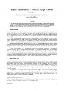
The semantic associated to UML+ is directly inspired by the Timed Statecharts defined by Kesten and Pnueli [7]. This formalism extends the traditional statecharts by specifying time limits for the execution of transitions. The semantics is defined with reference to a dense time domain. This implies that the system may deal with arbitrarily close time events. Transitions are classified in two types: immediate ones and timed, or waiting, transitions. Immediate transitions
2
do not depend on time: they are executed when a triggering event occurs. When no immediate transition is enabled, the time can flow with the state of the system remaining unchanged. On the contrary, timed transitions are independent from events. They are associated with a time interval specified giving a minimum and a maximum waiting time: the transition cannot be executed before the minimum or after the maximum waiting time. If no event changes the current state, the timed transition must be executed before the maximum waiting time. In Timed Statecharts negated events can appear in the conditions which guard the execution of transitions. The concept of “step” is associated with the execution of an immediate transition; a reaction to an event may occur several steps after its generation, but still in the same timestamp. This kind of semantics is based on the fact that every generated event “persists” until the time does not flow. The time may flow only if all the transitions which were enabled by that event have been executed. In this way, several transitions triggered by the same event e are executed before the time becomes grater than the time of the occurrence of e. {e1, e2}
S1
t1: e1
e4 [t1; t2]
S2 S3
t2: e1 [not e3]
Fig. 1 A UML+ statechart
Timed Statecharts have been further extended in UML+ to accommodate most of the syntax found in UML State Diagrams that is not present in Timed Statecharts; for instance, inter-level transitions and fork transitions are allowed in UML+. In UML+ it also possible to associate transitions with both events and time intervals (see for instance the transition from S3 to S1 in Fig. 1). UML+ extension allows the modeler to associate a set of events to a transition, indicating that the transition is triggered by the concurrent occurrence of the set of events (see the transition from S2 to S1 in Fig. 1). In UML+ guards can make reference to events. It is possible, for instance, to specify that a given transition is executed if event e1 occurs while event e3 is not occurring (see the transition from S2 to S3 in Fig. 1). A detailed definition of UML+ can be found in [10,11,12].
3
A brief introduction to UML-RT
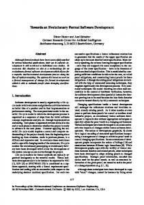
UML-RT is an extension of UML that addresses real-time issues. It provides a formalism to handle active objects. An active object is called a Capsule in UML-RT and it communicates with other capsules through asynchronous messages, which are sent and received through Ports. A Port is defined by a Protocol that defines which messages can be sent through a port (Out messages) and which messages a port accepts (In messages). Given a Protocol, its conjugate is always defined, by simply inverting the In and Out messages. The State Diagrams associated to each capsule have the usual syntax and semantic as in plain UML, including the “run to completion” behavior [8]. The only additional constraint is
3
that any message (except internal messages, which remain in the boundaries of the State Diagram) has always to be referred to a Port. Protocol1
Ports
Incoming
Protocol2
Outcoming
Incoming Outcoming
Capsule1
Capsule2
Fig. 2 Capsules and ports in UML-RT
Capsules are connected through Connectors. A Connector binds two different Ports with compatible Protocols. A protocol is always compatible with its conjugate; a protocol to be compatible with another one has to accept as In messages a superset of the other protocol’s Out messages and has to send a subset of the messages accepted by the other protocol. Statecharts
Behavior1
Behavior2
Connector Capsule1
Capsule2
Fig. 3 Connectors and State Diagrams in UML-RT
UML-RT mainly focuses on the concept of active component (the Capsule) and it doesn’t directly address real-time constraints. The concept of time can be found in standard UML-RT libraries –mainly thanks to the Timer class stereotype– but not directly in the modeling language. UML-RT is implementation oriented: it is conceived to be used with a complete library in a language of choice, usually abstracting form the underneath platform. By embedding code fragments in transitions and states (as defined in plain UML) a UML-RT model can be directly translated to code (Rational Rose RealTime being the reference tool for generating working embedded distributed systems from UML-RT models).
4
From UML+ to UML-RT
UML+ is a formal notation to express the desired behavior and the constraints of real-time systems; it can capture and formalize real-time requisites. UML+ models are written in a visual language very close to standard UML 1.4, and can be translated in a formal language and checked to verify that the systems behave as required and that the constraints are satisfied.
4
4.1
A case study
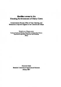
In the rest of the paper an example is used to illustrate the proposed approach. The system to be modeled and developed is the Generalized Railroad Crossing (GRC) [16], one of the best known benchmarks proposed in the literature for evaluating formalisms and tools dealing with real-time software.
I dm dm -g RI
g X
II
RO R
Fig. 4 GRC regions of interest
The system to be modeled operates a gate at a railroad crossing. The railroad crossing I lies in a region of interest R (see Fig. 4). Trains travel through R on K tracks in one direction (having trains traveling in both directions does not change the complexity and relevance of the case study). Trains can proceed at different speeds, and can even pass each other. Only one train per track is allowed to be in R at any moment. Sensors indicate when each train enters and exits regions R and I. Point RI and RO indicate the position of the entrance and exit sensors for region R. II indicates the position of the sensor which detects trains entering region I. dm and dM are the minimum and maximum time taken by a train to cross RI-II zone. hm and hM are the minimum and maximum time taken by a train to cross zone I. g is time taken by the bars of the gate for moving from the completely open to completely closed position.
4.2
UML+-RT: making UML+ component-aware
In order to support component-based development we have to make UML+ component-aware. For this purpose we adopt UML-RT representation of components, i.e., the capsules. This choice was taken because capsules are a satisfactory formalism, and because in this way it is easier to convert UML+ models into UML-RT models. The result of merging UML+ (featuring the Timed Statecharts [7]) and UML-RT is a new modeling language called UML+-RT. UML+ specifications of real-time system are essentially composed of class diagrams and object diagrams; the instances of classes are active objects and their behavior is defined by the associated Timed Statecharts. The structure of the system is defined by an Object Diagram that is used to connect the class instances that compose the system. In UML+-RT we retain the same organization. As an example, let us consider the model of the GRC. Fig. 5 illustrates the class diagram of the system, where capsules, ports and protocols are explicitly modeled. The object diagram is used to define the first level capsule. This is relatively straightforward, since the Component Diagram of UML-RT is a specialization of the UML Collaboration Diagram [1,9], as are the object diagrams. Fig. 6 illustrates the structure of the railroad crossing system in terms of capsules and connections, highlighting the connections to ports.
5
GateProtocol
+ / gatePort
+ / gatePort~
close () open ()
Gate + / gatePort : GateProtocol~
Controller
+ / gatePort : GateProtocol
1..*
+ / trackPort : TrackProtocol + / trackPort Main
TrackProtocol arriving () crossing () + / controllerPort~ leaving ()
Track + / controllerPort: TrackProtocol~
Fig. 5 UML+-RT Class Diagram
/ gate: Gate
+ / gatePort + / gatePort / controller : : GateProtocol~ : GateProtocol Controller
n
/ track: Track
+ / trackPort: + / controllerPort: TrackProtocol TrackProtocol~
Fig. 6 Main Capsule: UML+-RT Component Diagram
The behavior of a Capsule is defined by the associated Timed Statechart. For instance, Fig. 7 describes the behavior of class Gate: it clearly indicates that the events which cause the state transitions are received through the gatePort. g atePort.close()
Up
Moving Down
gatePort.clo se() [t_gate, t_gate]
Mo vingUp
g atePort.open() gate Port.open()
[t_g ate, t_gate]
D own
Fig. 7 Timed statechart for the Gate class
4.3
Dealing with synchronous semantics
UML+ adopts the synchronous semantics of Timed Statecharts. Synchronous semantics –although useful in the analysis phase and ideal for verification by model checkers– is unrealistic in the implementation phase. In a real system there are no cheap and easy ways to verify that two events are concurrent, to make two transitions fire simultaneously, and when the system is distributed it is not even easy to process messages in the same order in which they were generated.
6
On the contrary, systems are implemented according to an asynchronous semantics. Most of the modeling tools that generate an implementation are based on asynchronous models. Hence it would be desirable to be able to transform UML+ synchronous specifications into asynchronous models, like UML-RT models. UML-RT was chosen as the target notation because it is probably going to become a standard, it is component oriented (an important aspect to facilitate reuse), and it is equipped with tools (one for all, Rational Rose RealTime) to directly generate working systems. The translation from UML+-RT to UML-RT is not simple. The “run to completion” semantics of the UML-RT State Diagrams is quite different from the “synchronous execution of transitions” semantics of Timed Statecharts adopted in UML+ and UML+-RT. This difference can lead to some hard problems, described in section 4.4. The problems that can arise are of two types: • Some model fragments simply do not make sense in UML-RT. For instance, in UML-RT it is not possible to deal with negated events or to associate a transition with a set of simultaneous events. • Some models have the same general meaning in UML-RT as in UML+, but their behavior is not actually the same. In the first case it is difficult to devise which UML-RT model would more closely represent the intended meaning of the given UML+ model. Therefore we decided not to translate models having this kind of characteristics, i.e., it is responsibility of the modeler to correct these situations. In the second case the model interpreted according to the UML-RT semantics could violate the properties that were proved valid for the same model interpreted according to UML+ semantics. In this case the modeler is invited to build a second, more realistic UML+ model that takes into account the execution environment, and is therefore able to predict whether properties will remain valid also in the implementation-oriented UML-RT model. The description of the problems mentioned above (and how to deal with them) follows.
4.4
Issues and problems with the translation from UML+-RT to UML-RT
Consider the transition from S2 to S1 and the transition from S2 to S3 in Fig. 1: managing concurrent events and negated events in UML-RT is impossible, therefore in these cases the translator issues a warning and does not produce any UML-RT model. It is the modeler who has the responsibility to produce a more realistic model having similar characteristics. For instance the transition from S2 to S1 could be modified as shown in Fig. 8. e2 (0, dt]
Sx
e1
S2
S1 e1 (0, dt]
Sy
e2
Fig. 8 A statechart handling “almost concurrent” events
7
The statechart in Fig. 8 prescribes that the transition from S2 to S1 happens when events e1 and e2 occur (in any order) in a [0, dt] interval. If dt is little the transition will happen when e1 and e2 occur in a very short –though finite– interval, while the original condition (given in Fig. 1) required that e1 and e2 occurred exactly at the same time. In practice there is generally no difference between the two specifications. In any case it is always possible to model-check the new version of the model containing the transition from S2 to S1 redefined as shown in Fig. 8, in order to assure that the desired properties still hold. Transitions involving negated events, timed transitions having tmin = tmax (i.e., transitions reacting to events that must occur at a precise time) and instantaneous transitions (i.e., transitions that take null time to execute, even though they are associated with some action), can be treated in a similar way. In particular, we can specify that two events do not occur in a short finite interval, or that an event occurs in a short finite interval, or that an action takes a short finite interval to complete.
s1
sx
e1 ^e2
e2
s2
s1
s2
e1 s2’
sy sx
e2
(0, dt] ^e2
s2”
sy
Fig. 9 A model containing simultaneous events (left) and the equivalent model with no simultaneous events.
Timed transitions, i.e., transitions bounded with a time interval [tmin, tmax], are easily represented in UML-RT when tmax > tmin. When a state having one or more of such outgoing timed transitions is entered clocks are set (via the UML-RT libraries) to tmin. When the state completes its activities (if any), it waits the expiration of the appropriate clock before evaluating the guards associated with the timed transitions, and finally fires one of the enabled transitions. Clocks can be set also on the upper bound tmax. In this case, if the state completes its activities after the upper bound, an exception is raised, reporting that the state activities have not respected the timing constraints specified in the original UML+-RT model. These exceptions are useful for testing; in any case it is a design decision how to handle them, i.e., whether to execute a transition even if the upper bound time has passed or to take a different action. Now let us consider the statechart reported in the left part of Fig. 9. In this case the statechart has a well defined meaning in UML-RT, but unfortunately the behavior of the system in UMLRT is not the same as in UML+. In fact in UML+ events e1 and e2 occur at the same time (i.e., in the same timestamp), while in UML-RT e2 will follow e1 with a finite (though probably little) delay, since events are extracted from the event queue one at a time. This means that the properties that hold for the UML+ model could be violated by the same model behaving according to UML-RT semantics. In these cases we have models that are easily translated into UML-RT, but whose behavior will not match the previously model-checked one. We decided to solve this problem by maintaining two models: one for the purpose of translation, and another for the purpose of model checking (see Section 5 ). The latter model must reflect the behavior of the target UML-RT model. This can be achieved in two ways: 1. The modeler explicitly represents that transitions take a non-null time, e.g., by assigning a positive lower bound to the time intervals associated with the transitions. For instance, the
8
UML+ model reported in the right part of Fig. 9 behaves as the UML-RT model reported in the left part of the same figure: event e2 follows event e1 after a finite time (not grater than dt). 2. The modeler explicitly models in UML+ the event queue that is implicitly assumed by UML-RT statecharts. This requires to set the maximum size of the queue. In both cases the size of the model increases very fast as the number of events that have to be taken into account in the realistic delay period increases. Fig. 10 illustrates a model exploiting a queue. The queue is a FIFO container that is loaded with the arriving events and releases them in a finite time, which represents the time actually needed to perform a transition. In the left part of Fig. 10 when e1 (or e4) occur, instead of issuing the events e2 (or e3) which would imply an instantaneous transition to state sy (or sz), the events e2q (or e3q) are issued. These events are “captured” by the queue (right part of Fig. 10), which will issue the event e2 (or e3) after a finite delay ≤ dt, thus causing the transition to sy (or sz). Note that here we made two assumptions: • The maximum time to handle a transition is dt. Therefore the transition is associated with a time interval (0,dt]. If a minimum time dt_min were also defined the time interval would be [dt_min,dt]. • The length of the queue is 1. In general the length of the queue is given by the maximum number of events that can arrive during time interval [0, dt]. In the case depicted in Fig. 10 e2 and e3 are considered mutually exclusive (at least in the considered situation, i.e., immediately after the transition from s1 to s2 or s3). s1
e1 ^e2q e4 ^e3q
s2
e2q / t=0
s3
sq3
t(0,dt] ^e2 initial
sx
e2 e3
t(0,dt] ^e3
sy sz
e3q / t=0
sq2
Fig. 10 A model featuring a queue
In Fig. 10 the notation t(0-dt] associated with a transition indicates that the transition has to occur in the interval (t,t+dt]. The notation t=0 indicates that clock t is reset. In this simple case this notation is actually not necessary (since t is always reset when exiting from state initial, t(0-dt] is equivalent to (0-dt] in the transitions from sq2 and sq3 towards initial). However, in longer queues it is necessary to use this notation to express properly the time constraints.
5
The development environment
Thanks to the adoption of Timed Statecharts, UML+-RT has well-defined semantics. This allowed us to write a program that translates UML+-RT models into timed automata, so that the model checking tool Kronos [3] can be used to verify properties [11]. This is sufficient to sup-
9
port the specification phase, but does not help much in the design and implementation phase. For this purpose we want to generate a UML-RT model that preserves the properties already formally verified. However, the original model has to be modified, since it features perfect concurrency or synchronicity, which cannot be generally implemented in a model featuring asynchronous semantics. The problem is to preserve the properties of the original model, but also to check that these properties do not rely on characteristics of the model that cannot be implemented in the real world. Our approach is to make incremental refinements of a UML+RT model until we achieve a model that can be safely translated into UML-RT. At first sight, this approach could seem to be a not very good trade-off, as long as most of the difficulties of the conversion are left with the modeler. However we believe that in this way some relevant advantages are achieved: • the modeler is guaranteed that the properties of the original model are maintained; • the modeler is guided in the modification of the model by the diagnostic messages provided by the translator; • the modeler achieves a deeper understanding of the model, as new details (like the realistic duration of a transition) are added; • the final model actually reflects the ideas of the modeler. Results of model checking
Specs (XMI+)
Analyst
Specs (T.A.) Translator
Model checker
UML+ RT tool
Warnings concerning models’ synchronicity
Implementation model (UML RT)
Model (UML RT) Translator
Designer
UML RT tool
Fig. 11 The envisaged programming environment
Fig. 11 illustrates the programming environment that implements the proposed approach. This environment supports a development process organized as follows. Initially the modeler creates a UML+-RT model without worrying about the implementation of the model. The product of this phase is an “ideal” model, whose properties are verified by means of the model checker. The ideal model is then processed by the translator, which tries the conversion into UMLRT. In general the translator will find problems with the synchronicity of the model (see section 4.4) that are notified to the modeler. The latter modifies the model in order to remove the most obvious problems (simultaneous events, negated events, etc.). The new model is again verified by means of the model checker. The resulting “more realistic” model M is finally translated into a UML-RT model MRT. This step is mainly devoted to replacing timed transitions with transitions triggered by events generated by timers; the setting, resetting, etc. of timers is determined by the translator on the
10
basis of the timed transitions. However, MRT will not behave exactly like M, e.g., because in M transitions are instantaneous, while in MRT they take a finite time. In order to verify the properties of MRT the modeler builds a second UML+-RT model M’, which modifies M in order to represent its behavior according to the rules of the UML-RT environment (e.g., by introducing suitable queues of events). In practice in this phase the modeler maintains two models: M’ for the purpose of model checking, and M for the purpose of translation into MRT. The behavior of MRT in the UML-RT environment is equivalent to the behavior of M’ in the synchronous model-checking environment. At the end of this process, MRT is the starting point for the coding and testing phases. In UML-RT it is still possible to refine the model, but the refinements should be careful to preserve the properties that were successfully checked (the verification of the properties of component-based implementations in known run-time environments is the subject of an ongoing research activity).
6
Validation
The system described in Section 4.1 has to operate the crossing gate in a way that satisfies the following two properties: Safety: The gate is closed during all occupancy intervals. Utility: If no train is in any occupancy interval, nor within ξ1 prior to an occupancy interval, nor within ξ2 after an occupancy interval, then the gate is open. Point X (see Fig. 4) is thus defined as follows: when a train enters zone X-II it is time to start closing the gate, so that bars will be completely lowered when the train arrives at II. The exact position of X depends on the speed of the fastest train. In order to have the gate closed when the fastest trains arrive at II, we must begin to close the gate dm-g time units after the train entered region R. If the train is slower the gate will be already closed when it enters the crossing region I.
Empty opening
[g,g]
Empty open
trackPort.arriving(n) ^gatePort.close() ccr++
trackPort.leaving(n) [cir=1 and ccr=1] ^gatePort.open() cir--, ccr-trackPort.arriving(n) ^gatePort.close() ccr++
Not empty trackPort.crossing(n) trackPort.arriving(n) cir++ ccr++ trackPort.leaving(n) Zone I engaged [cir>1] ccr--, cir-trackPort.leaving(n) trackPort.crossing(n) [cir=1 and ccr>1] cir++ cir--, ccr-Zone I free
trackPort.arriving(n) ccr++
Fig. 12 The statechart of capsule Controller
11
The behavior of the controller is defined as specified in Fig. 12. The idea is that the Controller counts the trains in the X-RO zone (by means of variable ccr) and in the II-RO zone (by means of variable cir). As soon as ccr becomes grater than zero the controller sends the close command to the gate. When ccr and cir become zero the open command is sent to the gate. The signals crossing and leaving correspond to the signals generated by the sensors II and RO, while signal arriving corresponding to point X must be delayed of dm-g time units with respect to the signal generated by sensor RI. It is responsibility of the Track components (whose statecharts are omitted because of space reasons) to satisfy these rules. The parameter n of the arriving, crossing and leaving events is the identifier of the track which issues the signal. An important observation: the statechart given in Fig. 12 cannot be analyzed by Kronos as it is, because integer variables (like ccr and cir) are not allowed in the timed automata analyzed by Kronos. Since the number of tracks is limited this problem can be easily solved by replacing the integer counters with finite state automata where each state represents a value. Moreover, the events cannot be parameterized: in the Kronos model arriving(n) must be replaced by arriving1, arriving2, …, arrivingN (where N is the number of tracks). This applies of course to crossing and leaving events as well. The model of the GRC described above was translated into a set of timed automata that satisfies the required properties (this was proven by means of the Kronos model checker). The model is relatively simple, thus it can be directly translated into a UML-RT model, but the latter would not always behave as the original UML+-RT model. In fact by applying our translator (which implements the concepts described in section 4) we obtain a set of warnings, indicating that a new model is needed to verify the actual behavior of the UML-RT system. The warnings by the translator concern the following issues: In the statechart of capsule Gate the reactions to events open and close are immediate. We • need a queue to simulate non instantaneous transactions, in this case a 2 events 2 place queue. The distance between an open and a close event is no less than g+hm (due to the behavior of the Controller). Being dt1 the time to handle one event, it must be 2 dt1 < (hm+g). For a real computer-based system this condition is very easily satisfied. In the statechart of capsules CounterCir and CounterCcr (not shown) there are instantane• ous transactions. In the worst case, N fastest trains enter region R simultaneously: they will enter region X-II simultaneously, they will enter region II-RO simultaneously and finally they will exit region I simultaneously. We need 2 queues to manage these simultaneous transitions: one for CounterCir and one for CounterCcr. In both cases two pairs of events are relevant: arriving-leaving for CounterCcr and crossing-leaving for CounterCir. Both the queues are organized as follows (N being the number of tracks). The queues are a 2 events 2N place queue. Being dt2 the time taken to process a single event, it must be (2 N dt2) < (dm+hm). In fact, in the worst case, N fastest trains entering simultaneously fill the queue with 2N events, which must be handled in no more than (dm+hm) time units (i.e., before all the trains leave the crossing). For a real computer-based system this condition is very easily satisfied. Capsule Track generates signal arriving exactly dm-g time units after receiving the signal • generated by sensor RI. Signal arriving is communicated instantly to the Controller. This is unfeasible in a real-life environment. We have to give time to a real-world controller to react: for this purpose we specify that signal arriving is issued (dm–g)–d_react time units after the signal from the sensor is received, where d_react is the time taken by the real environment to react to an event (including event handling, transmission, etc.).
12
Following the principles illustrated in section 5 we built a “more realistic” UML+-RT model. This model was then translated into UML-RT, and the resulting model was tested by means of AnyLogic, a tool that provides a simulation environment for UML-RT models. The simulation showed that the system actually behaves as required. The simulation can be seen at http://www.xjtek.com/applications/?area=traffic (the model can be downloaded from the same site). Of course the simulation does not guarantee that sooner or later an erroneous situation will occur. In order to exclude this possibility we need to formally prove the properties of the system. For this purpose, we also built –following the indications of the translator reported above– the model that reproduces the behavior of the environment. This model –translated into timed automata and checked by means of Kronos– showed that the system’s behavior actually satisfies the requirements. Note that in order to satisfy the requirements, d_react has to be given a proper value. Such value can be computed taking into account the delays introduced by the queues and the characteristics of the model or –more simply– by means of a trial-and-error process. In fact by running Kronos with half a dozen different values of d_react we were able not only to find safe values, but also the minimum safe value. The Kronos model was also used to find unsafe working conditions for the system (e.g., dm too short with respect to the speed of the gate). Modifying the simulation model accordingly we were able to simulate with AnyLogic the occurrence of erroneous situations.
7
Conclusions and related work
Several research activities were carried out in order to provide UML with formal semantics. However, such initiatives assume perfect technology (like [17]) or are oriented to providing UML with a precise underlying model (like [18]). In fact, one of the main obstacles to the application of rigorous development techniques is the difference between real-time application software and functional design (which adopt simplifying assumptions, like instantaneous and perfect communications, synchrony of interaction with the environment, or atomicity of actions) and the physical real-time systems [19]. In order to solve the “synchrony assumption” Taxys provides a compiler that derives a verifiable model from programs written in Esterel and C [20]. In particular, the model includes the specification of an “event handler” that represents the interface between the external environment and the real-time application (and plays a role similar to our event queues). The work presented here is an initial effort to tackle the problem of bridging a perfect, synchronous, specification-oriented UML-based formalism with the real, imperfect, asynchronous implementation world. In particular we addressed the conversion of UML+ (an extension of UML that is suitable for the specification of real-time systems [11]) into a notation suitable for implementation, namely UML-RT, with the constraint that the final model retains the properties of the original model. This goal required to add the concept of component (or capsule) to UML+, and to map the synchronous semantics of UML+ onto the asynchronous semantics of UML-RT. The first task was easily solved by borrowing the component notation of UML-RT. The graphical language obtained (called UML+-RT) integrates the component-oriented concepts of UML-RT with the elements of UML+, and specially with Timed Statecharts [7]. Much
13
harder is the conversion of a synchronous model into an asynchronous one. We propose a translation process based on incremental refinements of the original UML+-RT model, guided by the translation tool and aiming at the complete removal of the features that model “ideal” situations that cannot be achieved in practice. In particular we propose to use two models, one to be translated into UML-RT for implementation, and another explicitly modeling the mechanisms of the real execution environment, in order to formally prove the properties of the system in real working conditions. Fig. 11 illustrates the development environment which exploits UML+-RT and the associated tools. The construction of the tools is complete, while their integration is in progress. The environment will enable a development process where the development is mainly based on model construction, and the relevant properties of the models can be checked step-by-step.
References 1. Modeling Language Guide, Rational Rose® RealTime, 2002, Rational Software Corporation, http://www.rational.com. 2. Marco Mauri, Estensione di UML per la specifica e la verifica delle proprietà di sistemi Real Time, 2001, Politecnico di Milano, Thesis (in Italian), http://www.polimi.it. 3. S. Yovine. Kronos, A Verification Tool for Real-Time Systems, Kronos User's Manual Release 2.2, Springer International Journal of Software Tools for technology Transfer, Vol. 1 October 1997. 4. V. del Bianco, L. Lavazza, M. Mauri, An application of the DESS modeling approach: The Car Speed Regulator, In Proc. SIVOOES 2001, Budapest 19 June 2001. 5. V. del Bianco, L. Lavazza, M. Mauri, A classification of real-time specifications complexity, In Proc. SIVOOES 2001, Budapest 19 June 2001. 6. A. Pnueli and M. Shalev, What is in a step: On the semantics of statecharts, In T. Ito and A. R. Meyer, editors, Intl. Conf. TACS '91: Theoretical Aspects of Computer Software, volume 526 of LNCS, pages 244--264. Springer, 1991. 7. Y. Kesten, A. Pnueli, Timed and Hybrid Statecharts and their Textual Representation, Weizmann Institute of Science, In Formal Techniques in Real-Time and Fault-Tolerant Systems 2nd International Symposium, 1992. 8. OMG Unified Modeling Language Specification, Version 1.4. http://www.omg.org. 9. B. Selic, G. Gullekson, P. T. Ward. Real-Time Object-Oriented Modeling. Wiley. 1994. 10. L. Lavazza, G. Quaroni, M. Venturelli. Combining UML and formal notations for modelling realtime systems. V. Gruhn (ed.) Proceedings of ESEC/FSE 2001, Vienna, Austria, September 10-14, 2001, ACM Press. 11. V. Del Bianco, L. Lavazza, M. Mauri. An introduction to the DESS approach to the specification of real-time software. CEFRIEL Technical Report RT01002, December 2001. 12. V Del Bianco, L. Lavazza, M. Mauri. A Formalization of UML Statecharts for Real-Time Software Modeling. The 6th Biennial World Conference On Integrated Design Process Technology (IDPT 2002), “Towards a rigorous UML” session, Pasadena, California, June 23-28, 2002. 13. C. Ghezzi, D. Mandrioli, A. Morzenti. TRIO, a logic language for executable specifications of realtime systems. The Journal of Systems and Software, Vol. 12, n. 2. Elsevier Science, May 1990. 14. V. Del Bianco, L. Lavazza, M. Mauri. Model Checking UML Specifications of Real Time Software. The Eighth IEEE International Conference on Engineering of Complex Computer Systems (ICECCS02), Greenbelt, Maryland, USA, December 2 - 4, 2002. 15. R. Alur, D.L. Dill, A Theory of Timed Automata, Theoretical Computer Science, n.126, 1994, pp. 183-235.
14
16. Heitmeyer C.L., Jeffords R.D., Labaw B.G., Comparing different approaches for Specifying and verifying Real-Time Systems, in Proc. 10th IEEE Workshop on Real-Time Operating Systems and Software (New York May 1993), 122-129. 17. Rik Eshuis, Roel Wieringa, Requirements-Level Semantics For UML Statecharts, Formal Methods for Open Object-Based Distributed Systems - FMOODS'2000, September, 2000, Stanford, California, USA 18. G. Reggio, E. Astesiano, C. Choppy and H. Hussmann, Analysing UML Active Classes and Associated State Machines -- A Lightweight Formal Approach, FASE 2000 - Fundamental Approaches to Software Engineering, LNCS 1783 (T. Maibaum Editor), Berlin, Springer Verlag, 2000. 19. Joseph Sifakis, Modeling real-time systems--challenges and work directions, EMSOFT01, Tahoe City, October 2001. Lecture Notes in Computer Science 2211. 20. V. Bertin, E. Closse, M. Poize, J. Pulou, J. Sifakis, P. Venier, D. Weil, and S. Yovine. Taxys = Esterel + Kronos. A tool for verifying real-time properties of embedded systems, Conference on Decision and Control, CDC'01. Orlando, December, 2001. IEEE Control Systems Society.
15