Formal Verification of a Flash Memory Device Driver - an Experience Report Moonzoo Kim1 , Yunja Choi2 , Yunho Kim1 and Hotae Kim3 1
2
CS Dept. KAIST, Daejeon, South Korea
[email protected] [email protected] School of EECS, Kyungpook National University, Daegu, South Korea
[email protected] 3 Samsung Electronics, Suwon, South Korea
[email protected]
Abstract. Flash memory has become virtually indispensable in most mobile devices. In order for mobile devices to operate successfully, it is essential that flash memory be controlled correctly through the device driver software. However, as is typical for embedded software, conventional testing methods often fail to detect hidden flaws in the complex device driver software. This deficiency incurs significant development and operation overhead to the manufacturers. In order to compensate for the weaknesses of conventional testing, we have applied NuSMV, Spin, and CBMC to verify the correctness of a multi-sector read operation of the Samsung OneNANDTM flash device driver and studied their relative strengths and weaknesses empirically. Through this project, we verified the correctness of the multi-sector read operation on a small scale. The results demonstrate the feasibility of using model checking techniques to verify the control algorithm of a device driver in an industrial setting.
1 Introduction Flash memory has become crucial component for mobile devices. Thus, in order for mobile devices to operate successfully, it is essential that the device driver of the flash memory operates correctly. However, as is typical of embedded software, conventional testing methods often fail to detect hidden bugs in the device driver software for flash memory since it is infeasible to test all possible scenarios generated from the complex control structure of the device driver. This deficiency incurs significant overhead to the manufacturers. For example, Samsung spent more project time and resources to test flash software than in developing the software. Limitations of conventional testing were manifest in the development of flash software for Samsung OneNANDTM flash memory [1]. For example, a multi-sector read function was added to the flash software to optimize the reading speed (see Section 3). However, this function caused numerous errors in spite of extensive testing and debugging efforts, to the extent that the developers seriously considered removing the feature. In this project, we have verified the correctness of a multi-sector read (MSR) operation of the Samsung OneNAND flash device driver by using NuSMV [6], Spin [13],
and CBMC [10] for an exhaustive analysis of a small size flash. These three model checkers use three different techniques, namely BDD-based model checking technique, explicit model checking technique, and SAT-based bounded model checking technique. The contributions of this project are three-folds. First, this project handles an interesting industrial problem to verify functional correctness of a controller with a large data structure. To date, there have been studies on verification of device drivers [12, 20, 25] and handling of large data structures such as arrays and linked lists [4, 8, 24]. Nevertheless, they either focus on debugging the compatibility of hardware-software interface or checking the correctness of standard operations for the data structure itself, rather than verification of the functional correctness of the device driver algorithm. The verification problem we have encountered with MSR is unique in that (1)MSR operates over a large set (potentially millions) of structured data and (2)It is necessary to verify the MSR as it is since our goal is to verify the correctness of existing code – optimization or aggressive abstraction of the algorithm itself should be minimized. Second, the model checking results provide a practical alternative verification technique to testing. Although the model checking results guarantee the correctness of MSR on a small size flash only, the exhaustive analysis results provide higher confidence compared to testings previously performed by Samsung. Furthermore, since MSR is a core logic used for most flash softwares with variations, the verification framework and strategy of the project can be used for other flash softwares with only modest efforts. Samsung highly valued the verification results and started to apply model checking to a flash file system as a subsequent project. Finally, we conducted a series of experiments to verify MSR by using three popular model checkers NuSMV, Spin, and CBMC. Our experiment results show that the selection of model checking technique makes significant effects on the performance of verifying MSR as well as verification effort to create and maintain a model which is also a crucial factor for successful application of model checking in industry. Although there exist a number of case studies on comparisons between different model checkers [26, 9, 11], comparison from the view-point of data-intensive application has not seen intensive study thus far; we believe that this issue is crucial to the success of verifying flash software. Furthermore, the empirical studies of the three different model checkers can provide valuable insight to the relative strengths and weaknesses of these popular model checking techniques.
2 Overview of the OneNAND Verification Project Our team for this project consists of two professors, one graduate student, and one senior engineer at Samsung. We worked on this verification project for six months. We spent the first three months reviewing the design and code of the device driver software and the characteristics of OneNAND flash. Most parts of the device driver software are written in C (∼30000 lines) and a small portion of the software is written in ARM assembly language.
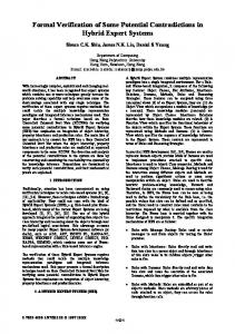
2.1 Overview of the Device Driver Software for OneNAND Flash Memory A unified storage platform (USP) is a software solution to operate OneNAND device. Figure 1 presents an overview of USP. USP allows applications to store and retrieve data on OneNAND through a file system. USP contains a flash translation layer (FTL) through which data and programs in the OneNAND device are accessed. FTL consists of three layers - a sector translation layer (STL), a block management layer (BML), and a low-level device driver layer (LLD). Generic I/O requests from applications are fulfilled through the file system, STL, BML, and LLD, in order. A prioritized read request for executing a program is made through demand paging manager (DPM) and this request goes to BML directly. A prioritized read request from DPM can preempt generic I/O operations requested from STL.
App1
App2
File System
App3 Demand Paging Manager (DPM)
generic I/O requests
prioritized read requests
Sector Translation (STL)
Flash Translation Layer (FTL)
Block Management (BML) Low Level Device Driver (LLD)
Unified Storage Platform
OS Adaptation Module
OneNAND Flash Memory Devices Fig. 1. An overview of USP
2.2 Overview of the Sector Translation Layer (STL) A NAND flash device consists of a set of pages, which are grouped into blocks. A unit can be equal to a block or multiple blocks. Each page contains a set of sectors. When new data is written to flash memory, rather than overwriting old data directly, the data is written on empty physical sectors and the physical sectors that contain the old data are marked as invalid. Since the empty physical sectors may reside in separate physical units, one logical unit (LU) containing data is mapped to a linked list of physical units (PU). STL manages this mapping from logical sectors (LS) to physical sectors (PS) and performs garbage collection. This mapping information is stored in a sector allocation map (SAM), which returns the corresponding PS offset from a given LS offset. Each PU has its own SAM. Figure 2 illustrates a mapping from logical sectors to physical sectors where 1 unit contains 4 sectors. Suppose that a user writes “AB” and then updates ‘B’ with ‘Q’ and
SAM1
Logical unit 7
Logical Physical Physical unit 1 sector offset LS0(‘A’) 0 0 1 2 3 (a) Write LS0 with ‘A’
Logical unit 7
SAM1 Physical Physical unit 1 offset LS0(‘A’) 0 LS1(‘B’) 1
Logical unit 7 SAM1 Physical Physical unit 1 offset LS0(‘A’) 0 LS1 (‘B’) 2 LS1(‘Q’)
(b) Write LS1 with ‘B’ (c) Update LS1 with ‘Q’
Logical unit 7 SAM1 Physical Physical unit 1 offset LS0(‘A’) 3 LS1(‘B’) 2 LS1(‘Q’) LS0(‘P’)
Logical unit 7 SAM1 Physical Physical unit 1 offset LS0(‘A’) 3 LS1(‘B’) 2 LS1(‘Q’) LS0(‘P’)
(d) Update LS0 with ‘P’
SAM4 Physical Physical offset unit 4 LS2(‘R’) 0 (e) Write LS2 with ‘R’
Fig. 2. Mapping from logical sectors to physical sectors
‘A’ with ‘P’ in order, and appends ‘R’ to make “PQR” finally. Suppose that a user writes LS0(‘A’) of LU7. STL assigns an empty physical unit PU1 to LU7, and LS0(‘A’) is written into PS0 of PU1 (SAM1[0]=0) as depicted in Figure 2(a). The user continues to write LS1(‘B’) of LU7, and LS1 is subsequently stored into PS1 of PU1 (SAM1[1]=1) (Figure 2(b)). The user then updates LS1(‘B’) with ‘Q’ and LS0(‘A’) with ‘P’ in order, which results in SAM1[1]=2 and SAM1[0]=3 (Figure 2(c) and Figure 2(d)). Finally, the user writes LS2(‘R’) of LU7 and STL finds that PU1 has no empty sector. Then STL adds a new physical unit PU4 to LU7 and yields SAM4[2]=0 (Figure 2(e)).
3 Multi-sector Read Operation USP provides a mechanism to simultaneously read as many multiple sectors as possible in order to improve the reading speed. The core logic of this mechanism is implemented in a single function in STL. Due to the non-trivial traversal of data structures for logicalto-physical sector mapping (see Section 2.2), the function for MSR is 157 lines long and highly complex, having 4-level nested loops. Figure 3 describes simplified pseudo code of these 4-level nested loops. The outermost loop iterates over LUs of data (line 2-17). The second outermost loop iterates until the LS’s of the current LU are completely read (line 4-15). The third loop iterates over PUs mapped to the current LU (line 614). The innermost loop identifies consecutive PS’s that contain consecutive LS’s in the current PU (line 7-10). This loop calculates conScts and offset, which indicate the number of such consecutive PS’s and the starting offset of these PS’s, respectively. Once conScts and offset are obtained, BML READ reads these consecutive PS’s as a whole fast (line 11). For example, suppose that the data is “ABCDEF” and each unit consists of four sectors and PU0, PU1 and PU2 are mapped to LU0 (“ABCD”) in order and PU3 and PU4 are mapped to LU1 (“EF”) in order as depicted in Figure 4(a). Initially, MSR
01:curLU = LU0; 02:while(curLU != NULL ) { 03: readScts = # of sectors to read in the current LU 04: while(readScts > 0 ) { 05: curPU = LU->firstPU; 06: while(curPU != NULL ) { 07: while(...) { 08: conScts = # of consecutive PS’s to read in curPU 09: offset = the starting offset of these consecutive PS’s in curPU 10: } 11: BML_READ(curPU, offset, conScts); 12: readScts = readScts - conScts; 13: curPU = curPU->next; 14: } 15: } 16: curLU = curLU->next; 17:} Fig. 3. Loop structures of MSR
accesses SAM0 to find which PS of PU0 contains LS0(‘A’). Then, it finds SAM0[0]=1 and reads PS1 of PU0. Since SAM0[1] is empty (i.e., PU0 does not have LS1(‘B’)), MSR moves to the next PU, which is PU1. For PU1, MSR accesses SAM1 and finds that LS1(‘B’) and LS2(‘C’) are stored in PS1 and PS2 of PU1 consecutively. Thus, MSR reads PS1 and PS2 of PU1 altogether through BML READ and continues its reading operation. The requirement for MSR is that the content of the read buffer should correspond to the original data in the flash memory when MSR finishes reading, as given by the following invariant formula for IN V . IN V : af ter M SR → (∀i.logical sectors[i] = buf [i])
SAM0~SAM4 Sector 0 Sector 1 Sector 2 Sector 3
1
PU0~PU4
0 1 2
E 1 AB C
3
SAM0~SAM4
3 F
2
(a) A distribution of “ABCDEF”
1
SAM0~SAM4
1
3 B
0 3
D
PU0~PU4
D F AC E
(b) Another distribution of “ABCDEF”
PU0~PU4
0 1 2
B 1 FE D
3
A C
(c) A distribution of “FEDCBA”
Fig. 4. Possible distributions of data “ABCDEF” and “FEDCBA” to physical sectors
In our verification tasks, we assume that each sector is 1 byte long and each unit has four sectors. Also, we assume that data is a fixed string of distinct characters (e.g.,
“ABCDE” if we assume that data is 5 sectors long, and “ABCDEF” if we assume that data is 6 sectors long). We apply this data abstraction since the values of logical sectors should not affect the reading operations of MSR, but distribution of logical sectors into physical sectors does. For example, for the same data “ABCDEF”, the reading operations of MSR are different for Figure 4(a) and Figure 4(b), since they have different SAM configurations (i.e. different distributions of “ABCDEF”). However, for “FEDCBA” in Figure 4(c) which has the same SAM configuration of Figure 4(a), MSR operates exactly same way as for Figure 4(a). Thus, if MSR reads “ABCDEF” in Figure 4(a) correctly, MSR reads “FEDCBA” in Figure 4(c) correctly too. In addition, we assume that data occupies 2 logical units. The number of possible distribution cases for l LS’s and n physical units, where 5 ≤ l ≤ 8 and n ≥ 2, increases exponentially in terms of n, and can be obtained by n−1 X
((4×i) C4 × 4!) × ((4×(n−i)) C(l−4) × (l − 4)!)
i=1
For example, if a flash has 1000 physical units with data occupying 6 LS’s, there exist a total of 3.9 × 10²² distributions of the data. As you have seen from Figure 4, the operations of MSR depend on the values of SAM tables and the order of PUs linked to LU. Therefore, MSR has characteristics of control-oriented program (4-level nested loops) and data-oriented program (large data structure consisting of SAMs and PUs) at the same time, although the values of PS’s are not explicitly manipulated.
4 Model Checking MSR using NuSMV NuSMV [6] is an open-source symbolic model checker branched from SMV. Although the SMV family has been widely used in the hardware industry, its application to industrial software has been limited to a couple of case studies [5, 19], mostly in the area of software specifications. Despite that explicit model checking has been favored in software verification, MSR has the following attractive characteristics, which have motivated the present authors to verify it with symbolic model checking. 1. MSR operates with a semi-random environment – sector writing is assumed to be random except for having some constraints. 2. MSR’s data structure can be abstracted in a simple array form with a couple of simple operations, such as assignments and equality checking. 3. MSR is a single-threaded program that can be verified independently from other modules. Unlike explicit model checking, which requires that the system environment be modeled explicitly, symbolic model checking allows free-variables to represent environmental inputs whose possible values are exhaustively evaluated through symbolic computation; this is one of the advantages of checking MSR using NuSMV. Whereas it is generally known that symbolic model checking performs poorly on applications with a large data structure and arithmetic operations, the main data structure in MSR is
relatively simple two 2-dimensional integer arrays (PUs and SAMs) with no arithmetic operations. MSR’s single-threaded structure is also suitable for using NuSMV, which is known to be inefficient in handling interleaves. 4.1 Model Translation We manually specified a NuSMV model for MSR after reading corresponding design documents and C code. The first challenge in creating a NuSMV model for MSR arises from the different modeling paradigms used in C and NuSMV; the NuSMV modeling language is dataflow-based, whereas C is a control-flow based language. Thus, translation of a C program into a NuSMV model requires introduction of control points to reflect control-dependent changes of data variables. For example, the simple procedural fragment of C in Figure 5 has three control points in terms of the data dependency. The conversion to a set of parallel statements is based on introducing a Boolean variable for each control point and making each statement dependent on the values of the control point variables. These parallel statements are then converted into NuSMV code using init and next operators as shown in the last column of Figure 5.
A fragment of C
Conversion to parallel statements based on control and data dependency
1: x=x-1; ĸ DP1 0: DP1=0; DP2=0; DP3=0; 1: if (!DP1) { x=x-1; DP1 =1;} 2: while(x>=0){ 3: y = x; ĸ DP2 2: if ((DP1 || DP3) && x>=0) { y = x; DP2=1; DP3=0; 4: x --;} ĸ DP3 } 3: if (DP2) { x--; DP3=1; DP2=0; }
Corresponding NuSMV code
init(DP1):=0; init(DP2):=0; init(DP3):=0; next(DP1):= 1; next(DP2):= case (DP1 | DP3) & (x >= 0) : 1; DP2 : 0; 1 : DP2; esac; next(DP3):= case (DP1 | DP3) & (x >= 0) : 0; DP2 : 1; 1 : DP3; esac; next(x):= case !DP1 | DP2 : x-1; 1 : x; esac; next(y):= case (DP1 | DP3) & (x >= 0) : x; 1 : y; esac;
Fig. 5. Conversion from a procedural program to parallel statements
The second challenge is to model the data structure in NuSMV. Even though SAMs and PUs can be abstracted into simplified two-dimensional integer arrays, modeling such data structure and operations for NuSMV is not a trivial task, especially because NuSMV does not support index variables for arrays. Circumventing the expressional limitations of NuSMV, the resulting translated MSR model consists of more than 1000 lines of code; the original C-code is 157 lines long. The third challenge involves setting the operational environment of MSR. MSR assumes randomly written logical data on PUs and a corresponding SAM records the actual location of each LS. Unfortunately, however, the writing is not purely random, which means the open environment of the symbolic model checking has to be con-
strained according to several rules; the followings are some of the representative rules applied to the random writing. 1. One PU is mapped to at most one LU. 2. If the ith LS is written in the kth sector of the jth PU, then the (i mod m)th offset of the jth SAM is valid and indicates the PS number k, where m is a number of sectors per unit (4 in our experiments). 3. The PS number of the ith LS must be written in only one of the (i mod m)th offsets of the SAM tables for the PUs mapped to the b mi cth LU. For example, for imposing the last two rules, we use the following weaker invariants, which include spurious value combinations in SAMs, to reduce the complexity of imposing invariants. Note that this weakening of invariants does not produce false positives when checking the IN V property specified in Section 3.
∀i, j, k (logical sectors[i] = P U [j].sect[k] → (SAM [j].valid[i mod m] = true & SAM [j].of f set[i mod m] = k & ∀p.(SAM [p].valid[i mod m] = f alse) i where p 6= j and P U [p] is mapped tob cth LU )) m 4.2 Performance Analysis We have performed a series of experiments in order to assess the feasibility and scalability of model checking the invariant property IN V .
Experimental settings and verification results We verified MSR using a workstation equipped with Xeon 5160 (dual core 3 GHz) and 32 gigabytes memory. The workstation runs 64 bit Fedora Linux 7 and uses NuSMV 2.4.3. The scalability of NuSMV model checking is assessed by measuring the amount of time and memory required to verify the IN V property as the number of physical units increases from 5 to 8 and the size of logical data increases from 5 to 7 sectors. Figure 6 shows the growth of time and memory consumption from these experiments; the verification time grows exponentially both with the number of physical units and the number of logical sectors (Figure 6 (a)). Note that the memory consumption shows better scalability than that of time consumption (Figure 6 (b)). Although NuSMV succeeds in verifying that the MSR satisfies the IN V property, the exponential time complexity limits the applicability of NuSMV model checking to only a small flash memory. As it requires about 11 hours and 550 megabytes of memory to verify the IN V property for the MSR model with 7 physical units and 7 logical sectors, we conclude that further experiments with larger numbers of physical units and logical sectors are meaningless.
100000
600
5 6 7
1000
A length of data
400 Magabytes
Seconds
500
A length of data
10000
5 300
6 7
200 100
100
0 5
6 7 A number of physical units
(a) Time consumption
8
5
6 7 A number of physical units
8
(b) Memory consumption
Fig. 6. Time and space complexities of NuSMV model checking
Dynamic reordering and time complexity The exponential growth of verification time is mainly due to the dynamic reordering of BDD variables to keep the symbolic representation of the state space as compact as possible. OBDD representations for a Boolean formula can be quite different in terms of the number of nodes representing the formula. Since finding optimal BDD variable orderings is an intractable problem [3], NuSMV periodically attempts to improve the orderings by moving each variable through the ordering to find its best location using the sifting algorithm [22]. While this ordering process is known to be effective in terms of reducing the state-space, it is time-consuming, as is clearly seen from our experiments. We observed that more than 90% of verification time was consumed for dynamic reordering. The NuSMV version of the MSR model (with 5 LS’s, 5 PUs) requires 365 BDD variables for its symbolic representation and generates more than 1,182,300 BDD nodes during the verification process, which is 12 times larger in size than the rule-of-thumblimit for effective reordering, i.e., 100,000. Note that the number of BDD variables encoding the MSR is undesirably large, mainly due to the encodings of data variables; it is necessary to encode at least 20 data variables for 5 PUs with 4 PS’s each. Even with a restricted domain, e.g., with the size of the data domain 5, each PS needs 6 (=3+3) Boolean variables, resulting in a total of 120. Since MSR also maintains a SAM of approximately the same size, we can deduce that more than 240 BDD variables are used for encoding the main data structure alone. Search depth and performance From the experiments, we note that the long search depth for checking MSR constitutes a major performance bottleneck. In [26], a case study on model checking a flight guidance system (FGS) is reported. FGS is encoded in a larger number of BDD variables, but shows better performance than that of MSR; one of the FGS models was encoded with 839 BDD variables and the peak number of nodes was 3,213,168. The major difference is that FGS requires less than 10 iterations for symbolic fixed-point computation, whereas MSR models require 37 - 53 iterations, because of the nested loops used in the MSR algorithm. The long search depth exacerbates memory and time complexity since reordering is performed at each search iteration. To assess the effect of long search depth on verification performance, we remodeled the MSR environment such that the random writing environment is explicitly modeled
with non-deterministic random value assignments. Note that adding a random writing routine increases the complexity of symbolic model checking especially in terms of the search depth; for 5 LS’s written in 5 PUs, each with 4 sectors, at least 5 × 5 × 4 = 100 iterations are required to simulate random writing. Experiments show that a model with a random writing routine requires 169 iterations for fixed-point computation, spending 10 times more verification time than the model with invariants. 4.3 Data Abstraction In our experiments, we have applied a simple data abstraction on the domain of LS’s to avoid the state-space explosion problem. Though the original LS’s range over integer domain, we can reduce the domain to a set of integer values where the total number of distinct values in the set equals to the number of logical sectors to read, because the MSR model as well as the IN V property requires only equality checking between LS’s and the read buffer. For example, 6 distinct values, e.g., {0,1,2,3,4,5}, would be enough for checking the IN V property for MSR with 6 logical sectors. In fact, two distinct values, {0,1}, for each data variable may be enough to check an equality condition a = b since all possible combinations of values {(a, b)|a, b ∈ N } can be partitioned into two equivalent classes, A = {(a, b)|a = b}, B = {(a, b)|a 6= b}, and one representative value pair per each equivalent class, e.g., (0,0) for A and (0,1) for B, is enough to cover all possible cases. Nevertheless, we cannot reduce our data domain uniformly to {(0,0), (0,1)} because of the constraints we have imposed on the MSR models; as mentioned in the previous sections, we have imposed several constraints for setting the operational environment of MSR instead of explicitly modeling the sector writing routine for performance reasons. One example of such invariants, as introduced in Section 4.1, constrains that no two logical sectors contain the same data. For example, suppose logical sectors[0] = logical sectors[1] and logical sectors[0] = P U [0].sect[0] & logical sectors[1] = P U [0].sect[1], then we can imply that logical sectors[0] = P U [0].sect[0] = P U [0].sect[1]. This implies to a contraction, SAM [0].of f set[0] = 0 & SAM [0].valid[0] = 1 and SAM [0].of f set[0] = 1 & SAM [0].valid[0] = 1, by the invariants introduced in Section 4.1. Therefore, we need at least k distinct values to distinguish k logical sectors.
5 Model Checking MSR using Spin Due to common characteristics of Promela and C, creation of a formal Promela model from MSR is more convenient compared to NuSMV. Furthermore, the Promela model of MSR was semi-automatically generated by using Modex [14] which is a general purpose translation tool from C to Promela. 5.1 Model Translation In a Promela model, the MSR environment (i.e., logical sectors, physical sectors and SAM) is specified such that all possible distributions of data into physical sectors are generated exhaustively through non-deterministic guarded commands.
Modex [14] translates the control structure of MSR such as if and while into corresponding Promela control structures. Other C statements are inserted as embedded C code into the Promela model starting with a keyword c expr{...} for Boolean expressions and c code{...} for assignments and function calls [14]. As a result, the Promela model generated by Modex has the same 4-level nested loops as MSR does. The embedded C codes are blindly copied from the text of the Promela model into the code of the verifier that Spin generates. In addition, we modified the generated Promela model to make the embedded C code work correctly and efficiently under the Spin verification environment. For example, linked lists of PUs and SAMs in MSR were replaced with arrays of PUs and SAMs. These modifications were performed through an explicit translation table given to Modex. Modex textually replaces C patterns in the table with the corresponding Promela codes specified in the table. Figure 7(a) shows an excerpt of MSR and the Promela code generated by Modex using the translation table of Figure 7(b). The total translation table used to generate a Promela model from MSR is 63 lines long. The translated Promela model is 250 lines long, including the embedded C code. The requirement property is specified by the assert statement assert( logical sectors[0]==buf[0] && logical sectors[1]==buf[1]...) located at the end of the MSR process.
5.2 Data Abstraction In explicit model checking, all system states are stored in a huge hash table explicitly. Thus, data structures in the model do not incur extra overhead, since data structures are stored into the state vector as they are, not through complex BDD encoding. MSR traverses a large amount of memory, most of which are taken by PUs and SAMs. The PUs and SAMs in embedded C code are tracked throughout the verification process, but are not stored in the state vector. 4 Instead, we add a new signature that represents the state of PUs and SAMs and put that signature into a state vector so that verification produces the correct result with this data abstraction. The signature is an ordered list of the physical locations of logical sectors (i.e. pairs of a PU number and a PS number). For example, the signature for Figure 4(a) is h(0,1),(1,1),(1,2),(2,3),(3,0),(4,1)i since ‘A’ is located at PU0’s PS1 and ‘B’ is located at PU1’s PS1 and so on. Therefore, there exists an one-to-one relation between signatures and states of PUs and SAMs and this abstraction preserves logical soundness according to the soundness theorem in [14]. Considering that the size of PUs is much larger than that of data, a significant amount of memory is reduced through this abstraction. For example, if 5 sectors long data is distributed over 10 physical units, the state vector should contain at least 80 (=2 × (10 PUs × 4 sectors)) bytes for PUs and SAMs. The corresponding signature is 4 bytes long (= 5 × (dlog2 10ebits + dlog2 4ebits)), resulting in a 95% reduction of the state vector size for PUs and SAMs only. 4
This data abstraction on embedded C data is achieved through c track keyword with Unmatched parameter. This feature has been available since Spin 4.1.
C code
Promela Code
do{ if (cur->SAM[sIdx] < DELETED){ fst_offset = cur->SAM[sIdx]; sIdx++; while (read_scts > 0){ if ((fst_offset+scts)==cur->SAM[sIdx]){ scts++; read_scts--; sIdx++; } else break; } error = BML_MRead(VNC->Vol, SHPC->startVsn + fst_offset, scts, buf); break; } cur = cur->Next; } while (cur != NULL);
do :: if :: c_expr{SAM[PU_id].offset[sIdx] != NULL;}; c_code{now.fst_offset=SAM[PU_id].offset[sIdx];};c_code{sIdx++;}; do :: c_expr{read_scts > 0}; if :: c_expr{now.fst_offset+now.scts==SAM[PU_id].offset[sIdx]}; c_code{scts++;}; c_code{read_scts++;}; c_code{sIdx;}; :: else; break; fi; :: else; -> break; od; inline_BML_MRead(PU_id,fst_offset,scts,buf); break; :: else; fi; c_code {PU_id = PU_id + 1;}; if :: c_expr{ !((PU_id)==nPU_LU0 || (PU_id)==MAX_PU) }; :: else; break; fi od;
(a) MSR C code and the corresponding Promela code Pattern in C code
Corresponding Promela code
(cur->SAM[sIdx]SAM[sIdx] ((fst_offset+scts)==cur... error=BML_MRead(... cur=cur->Next (cur!=NULL)
c_code{now.fst_offset = SAM[PU_id].offset[sIdx];} c_expr{now.fst_offset+now.scts==SAM[PU_id].offset[sIdx]} inline_BML_MRead(PU_id,fst_offset,scts,buf) c_code{ PU_id = PU_id + 1;} c_expr{ !((PU_id) == nPU_LU0 || (PU_id) == MAX_PU) }
(b) A translation table for Modex Fig. 7. An excerpt of MSR and the corresponding Promela code created by Modex
5.3 Performance Analysis We used Spin 4.3.0 on the same computing platform where NuSMV experiments were performed. We have performed two series of experiments with different lengths of data as well as different numbers of physical units. The first series of experiments are performed without data abstraction and the second series of experiments are performed with the data abstraction. 5 Figure 8 illustrates performance data for checking the requirement property. In all of the experiments, Spin shows that the requirement property is satisfied. For experiments without data abstraction, Spin verified a flash containing 10 PUs and 5 logical sectors in 356 seconds, consuming 9.6 gigabytes of memory. In comparison, experiments with data abstraction, denoted as “n(abs)” in Figure 8, Spin consumes 5
These experiments were performed without lossy compression such as bitstate hashing. For experiments without data abstraction, the -DCOLLAPSE option was used.
A length of data 5(abs) 6(abs) 7(abs) 8(abs) 5 6 7 8
Seconds
1000 100 10 1 5
100000 A length of data 5(abs) 6(abs) 7(abs) 8(abs) 5 6 7 8
10000
Megabytes
10000
1000
100
6 7 8 9 10 A number of physical units
5
6 7 8 9 10 A number of physical units
(a) Time consumption
(b) Memory consumption
Fig. 8. Time and space complexities of Spin model checking
2.1 gigabytes of memory in 230 seconds, which reduces the memory consumption by 78% and the verification time by 35%, as shown in Table 1. Data abstraction reduces not only memory consumption but also verification time, since the time taken to store and retrieve state space is reduced as well.
# of physical units 5 6 7 8 9 10 Memory reduction 17% 38% 57% 68% 74% 78% Time reduction 23% 24% 26% 32% 34% 35% Table 1. Memory and time reductions for 5 logical sectors due to the data abstraction
As can be seen in Figure 8, the memory consumption and verification time increase exponentially in relation to the number of physical units. The bottleneck in this verification task is its memory consumption. Spin handles states explicitly, and thus the exponentially increasing number of possible distribution cases accordingly causes an exponential increase of memory. Compared to NuSMV, however, Spin is significantly faster for the verification tasks of this type. For example, for a test case of 7 logical sectors and 7 physical units, Spin takes 27 minutes with 11.4 gigabytes with data abstraction, while NuSMV takes more than 11 hours with 550 megabytes. In Spin, scalability on memory consumption is a larger problem while verification time is a more serious problem in NuSMV.
6 Model Checking MSR using CBMC CBMC [10] analyzes C code directly without an abstract model and produces a bitlevel accurate analysis result. Although, a SAT formula straightforwardly translated from a C program can be huge including millions of Boolean variables and clauses, this
huge formula can be solved by a SAT solver in an acceptable time for many practical cases [2]. 6.1 Model Translation CBMC does not need an explicit model translation, since it can directly analyze MSR C code. However, to obtain meaningful verification result, we have to build an environment that provides only valid configurations of a flash memory to MSR, as we did for NuSMV experiments. We specified an environment model using assume statements ( CPROVER assume(Boolean expression)) and the environment model is similar to that of NuSMV experiments since both of them share most of the invariants (e.g. invariants in Section 4.1). For the numbers of loop unwindings for bounded model checking, we can get a valid upper bound of each loop from the loop structures described in Section 3. – The outermost loop iterates at most L times, where L is a number of LUs. – The second outermost loop iterates at most 4 times, since one LU contains 4 LS’s (i.e., readScts≤ 4) and at least one LS is read at each iteration. – The third loop iterates at most M times where M is a total number of PUs. – The innermost loop iterates at most 4 times, since one PU contains 4 PS’s. For example, L = 2 and M = 5 for Figure 4(a). 6.2 Performance Analysis We used CBMC 2.6.0 (with MiniSAT 1.1.4) on the same computing platform where NuSMV and Spin experiments were performed. We performed two series of experiments with different lengths of data as well as different numbers of PUs. One series of experiments verifies MSR with a linked list representation of PUs as written in MSR C code. The other series of experiments verifies MSR with an array representation of PUs as written in NuSMV and Spin models. In all of these experiments, the requirement property specified by the assert statement assert( logical sectors[0]==buf[0] && logical sectors[1]==buf[1]...) is satisfied. Figure 9 illustrates the performance results of these two series of experiments. Experiments with array representation are denoted as “n(array)”. In addition, Table 2 enumerates the sizes of SAT instances of MSR problems. For example, if 8 sectors long data is distributed over 10 PUs, then the corresponding SAT formula contains 3.3 × 10⁶ Boolean variables and 11 × 106 clauses. Compared to the results of Spin experiments, CBMC demonstrates better performance in both verification time and memory consumption for large problem instances. For example, when data is 7 sectors long and the number of PUs is 7, CBMC takes 688 seconds and consumes 418 megabytes of memory while Spin with the data abstraction takes 1604 seconds and consumes 11.4 gigabytes of memory. CBMC demonstrates better performance compared to NuSMV for large problem instances, too. 6 Note that for 6
We could not use the SAT-based bounded model checking capability of NuSMV in this project, since the smallest problem instance took more than 3 hours.
A length of data 5 6 7 8 5(array) 6(array) 7(array) 8(array)
Seconds
1000.0
100.0
10.0 5
1000
A length of data 5 6 7 8 5(array) 6(array) 7(array) 8(array)
Megabytes
10000.0
100
10
6 7 8 9 10 A number of physical units
5
(a) Time consumption
6 7 8 9 10 A number of physical units
(b) Memory consumption
Fig. 9. Time and space complexities of CBMC model checking
×106 5 6 7 8
var 1.3 1.3 1.3 1.4
5 clause 4.2 4.3 4.4 4.5
var 1.6 1.6 1.7 1.7
6 clause 5.3 5.5 5.6 5.8
var 1.9 2.0 2.0 2.1
7 clause 6.6 6.7 6.9 7.1
var 2.3 2.3 2.4 2.5
8 clause 7.9 8.0 8.3 8.4
var 2.7 2.7 2.8 2.9
9 clause 9.2 9.4 9.7 9.9
10 var clause 3.0 11 3.1 11 3.2 11 3.3 11
Table 2. The sizes of the SAT CNF instances of MSR with different configurations
the problem of the same size, NuSMV takes 11 hours and consumes 550 megabytes of memory. If CBMC uses array representation instead of linked list for PUs, the verification performance is improved even better; for the same experiment with array representation, CBMC takes 203 seconds and consumes 148 megabytes of memory . This high performance of solving huge SAT formulas (see Table 2) in a modest time is obtained by the advanced heuristics used by modern SAT solvers. Although SAT is a NP-complete problem, many structured problem instances can be solved in an acceptable time [21, 23] with help of heuristics such as VSIDS or random restart [17]. Detailed analysis on these CBMC based experiments will be reported in a separate article.
7 Discussion In this section, several issues are discussed on the basis of our experience in this project. 7.1 Application of Model Checking in Industrial Software Projects Formal verification techniques are being evaluated for experimental purposes for software projects in major electric device manufacturers in Korea such as Samsung, as a complement of software testing, which has thus far been the software verification
technique. Samsung performed the majority of testing for the OneNAND device driver randomly, which does not provide sufficient coverage for detecting bugs even with a huge number of test cases, since there are astronomically many possible scenarios (see Section 3). Even with a scalability limitation, this OneNAND verification project was evaluated as a success as it confirmed the correctness of the MSR, which could not be assumed through testing, for a small flash memory; exhaustive exploration through model checking provides high confidence in the correctness of MSR. 7.2 Advanced Abstraction Techniques We have applied a basic data abstraction (e.g. a fixed string “ABCDE” serves for all 5 sectors long strings) described in Section 3 to reduce state space of MSR. In addition, we used weaker invariants to model the environment of MSR with reduced complexity, which does not produce false positives (see Section 4.1). However, more aggressive abstractions based on symmetry turned out to be hard to apply for this project, since we have to validate several assumptions on MSR code to exploit symmetry, which requires inductive proof techniques which are beyond the scope of the project. For experiments in NuSMV, only primitive data type reductions are applied to reduce the search space. Other well-exercised and aggressive abstraction techniques, such as predicate abstraction [15], counter-example-guided abstraction-refinement (CEGAR) [7], and temporal case splitting [18], might be applied to enhance the performance of NuSMV verification. Nevertheless, their effectiveness on MSR is questionable due to the following reasons: 1. A simple trial experiment shows that case-splitting does not always improve the verification performance for MSR. For example, we have checked each sub-case of the IN V property, af ter M SR → logical sector[i] = buf [i], separately for each i, where 0 ≤ i ≤ 4 and a flash has 7 PUs. The verification time required for the case i = 1 is about 840 seconds. Note that the time required for checking the original IN V property for the same setting is only 530 seconds. 2. The predicate abstraction or CEGAR approach can be effective when checking the safety or compatibility of a software module whose unrelated branches of control flow and/or large data domains can be safely abstracted away. In the case of MSR, however, each control branch contributes to its functional correctness, leaving small chances for reducing complexity by abstraction. We also note that the data domain in MSR has already been reduced to a minimal set (e.g. {0,1,2,3,4} for 5 sectors long data) for the verification using NuSMV. For Spin experiments, besides the one-to-one data abstraction described in Section 5.2, there exist other data abstraction techniques that have yet to be applied. For example, [16] proposes a memory-efficient hash table that implements a sophisticated hash table structure which uses less memory at the cost of operation time overhead. To apply this technique, however, we should modify the Spin source code to change its hash table structure, which is beyond the scope of the project. For CBMC experiments, there exist not much room to apply aggressive abstraction to MSR itself, since the MSR C code should not be modified much for abstraction
purpose. However, the environment model of MSR can be built in an efficient way. For example, the abstraction of the linked list representation of PUs into array based one results in performance improvement as shown in Figure 9, although this abstraction slightly modifies the MSR code to work on the array of PUs instead of the linked list of PUs. 7.3 Scalability of Model Checking Even with the abstraction techniques noted in Section 7.2, it is not clear that model checking can be an overall solution for verifying software similar to MSR. For software handling a large data structure, model checking has an inherent scalability limitation, since the size of the environment to be modeled and analyzed is extremely large, even with symmetry reduction or state partitioning. Thus, for software similar to MSR, it still seems appropriate to utilize human expertise through a theorem prover, constraint solving, or inductive proofs. For this aspect, invariant based modeling is preferable since invariant based model can be adapted to specify a target system for theorem proving. We are planning to study this problem further by using a theorem prover.
8 Conclusion and Future Work We have shown that a difficult verification problem in industrial software can be tackled using automated formal verification tools. Though the project was conducted on a small-scale, Samsung highly valued the verification result. It was also confirmed that comprehensive verification techniques have feasible use and that they can complement testing or provide an alternative solution. This has motivated our next project; we plan to analyze a flash file system to check data consistency at the events of random power-off. At the same time, we could understand relative strengths and weaknesses of three popular model checking techniques empirically - BDD-based one, explicit one, and SAT-based one. We will analyze the experimental results of CBMC further, since CBMC demonstrated the best verification performance in this project and requires minimal verification efforts due to direct C analysis capability. The experience gained in this project also led the authors to realize the practical limitations on the scalability of model checking and the necessity of conducting further research to address the issue through the use of smart abstraction techniques and/or by utilizing human expertise.
References 1. Samsung OneNAND fusion memory. http://www.samsung.com/global/business/ semiconductor/products/fusionmemory/Products OneNAND.html. 2. SAT competition 2007: a satellite event of the SAT 2007 conference, 2007. http://www.satcompetition.org/2007/. 3. B. Bollig and I. Wegener. Improving the variable ordering of obdds is np-complete. IEEE Transactions on Computers, 45(9), September 1996. 4. A. Bouajjani, P. Habermehl, A. Rogalewicz, and T. Vojnar. Abstract regular tree model checking of complex dynamic data structures. In 13th International Static Analysis Symposium, pages 52–70, 2006.
5. W. Chan, R. J. Anderson, P. Beame, S. Burns, F. Modugno, D. Notkin, and J. D. Reese. Model checking large software specifications. IEEE Transactions on Software Engineering, 24(7):498–520, July 1998. 6. A. Cimatti, E.M.Clarke, E. Giunchiglia, F. Giunchiglia, M. Pistore, M. Roveri, R. Sebastiani, and A. Tacchella. NuSMV 2: An opensource tool for symbolic model checking. In Proceeding of International Conference on Computer-Aided Verification, 2002. 7. E. Clarke, O. Grumberg, S. Jha, Y. Lu, and H. Veith. Counterexample-guided abstraction refinement. In Proceedings of the 12th International Conference on Computer Aided Verification, pages 154–169, July 2000. 8. P. T. Darga and C. Boyapati. Efficient software model checking of data structure properties. In 21st Annual ACM SIGPLAN Conference on Object-Oriented Programming Systems, Languages, and Applications, 2006. 9. Y. Dong, X. Du, G.J. Holzmann, and S.A. Smolka. Fighting livelock in the GNU i-protocol: a case study in explicit-state model checking. International Journal on Software Tools for Technology Transfer, (4), 2003. 10. E.Clarke, , D.Kroening, , and F.Lerda. A tool for checking ANSI-C programs. In Tools and Algorithms for the Construction and Analysis of Systems (TACAS 2004), pages 168–176. Springer, 2004. 11. C. Eisner and D. Peled. Comparing symbolic and explicit model checking of a software system. In SPIN Workshop, 2002. 12. T. Ball et al. Thorough static analysis of device drivers. ACM SIGOPS Operating Systems Review, 40(4):73–85, 2006. 13. G.J.Holzmann. The Spin Model Checker. Wiley, New York, 2003. 14. G.J.Holzmann and R.Joshi. Model-driven software verification. In Spin Workshop, 2004. 15. S. Graf and H. Saidi. Construction of abstract state graphs with PVS. In Proceedings of the Computer Aided Verification(CAV 1997), pages 72–83, 1997. 16. J.Geldenhuys and A.Valmari. A nearly memory-optimal data structure for sets and mappings. In Spin Workshop, 2003. 17. L.Zhang and S.Malik. The quest for efficient boolean satisfiability solvers. In Computer Aided Verification, 2002. 18. K. McMillan. Verification of infinite state systems by compositional model checking. In Conference on Hardware Design and Verification Methods, 1999. 19. S. P. Miller, A. C. Tribble, M. W. Whalen, and M. P.E. Heimdahl. Proving the shalls: Early validation of requirements through formal methods. International Journal on Software Tools for Technology Transfer, 8(4):303–319, 2006. 20. D. Monniaux. Verification of device drivers and intelligent controllers: A case study. In 7th ACM and IEEE international conference on Embedded Software, 2006. 21. MK Prasad, P. Chong, and K. Keutzer. Why is ATPG easy? Design Automation Conference, 1999. Proceedings. 36th, pages 22–28, 1999. 22. R. Rudell. Dynamic variable ordering for ordered binary decision diagrams. In International Conference on Computer-Aided Design(ICCAD), November 1993. 23. R.Williams, C.P.Gomes, and B.Selman. Backdoors to typical case complexity. In Intl. Joint Conf. on Artificial Intelligence, 2003. 24. S.Anand, C.S.Pasareanu, and W.Visser. Symbolic execution with abstraction. Software Tools for Technology Transfer, 2008. 25. T.Witkowski, N.Blanc, D.Kroening, and G.Weissenbacher. Model checking concurrent linux device drivers. In Automated Software Engineering, November 2007. 26. Y.Choi. From NuSMV to SPIN: Experiences with model checking flight guidance systems. Formal Methods in System Design, pages 199–216, June 2007.