8th IEEE Workshop on Network Security 2013
Formal Verification of Mobile Agent Based Anomaly Detection in Wireless Sensor Networks Muhammad Usman, Vallipuram Muthukkumarasamy, and Xin-Wen Wu School of Information and Communication Technology Griffith University, Gold Coast Campus, Queensland 4222, Australia
[email protected],
[email protected],
[email protected] Abstract— Mobile agent technology offers a number of advantages to resource constrained Wireless Sensor Networks (WSNs) by facilitating parallelism, code and data dissemination, localization, and distributed security services. As part of the second line of defense for WSNs, anomaly detection schemes are also benefiting from mobile agent technology. The formal verification can be used to validate the correctness of a system using formal specifications. This study employs Behavior Trees (BTs) for formal verification of mobile agent based anomaly detection system in WSNs. We employed BT based formal semantics to integrate the behavior projection of different components of anomaly detection system. The Symbolic Analysis Laboratory (SAL) tool is used to formally specify the behavior tree model. The analysis based on Linear Temporal Logic (LTL) theorems validates the completeness and consistency of the formal model of mobile agent based anomaly detection system. Index Terms— Anomaly detection, behavior tree, formal verification, mobile agent, wireless sensor networks (WSNs)
I. INTRODUCTION Over the years, Wireless Sensor Networks (WSNs) have emerged as a major research area in the domain of information and communication technology mainly because of their popularity in several application areas such as military, target tracking, wildlife monitoring and wireless smart home sensor networks [1]. The correct functioning of such data centric applications is highly dependent on the accuracy of received data. However, sensor nodes and sensor readings are vulnerable to in situ and in transit faults, errors, and attacks [2]. As a second line of defense for WSNs, anomaly detection system helps in detecting and mitigating anomalies caused by faults, errors, and attacks. The mobile agent technology offers several advantages such as fault tolerance, autonomy, and scalability. Mobile agents are being effectively used in WSNs for different purposes such as code and data dissemination, localization, and also for security services such as anomaly detection. Over the years, several mobile agent based anomaly/ intrusion detection schemes are proposed for WSNs [3] – [6]. In these schemes, mobile agents are employed for various purposes such as control messages transmission and random sampling of sensor nodes. In our previous work, we suggested the use of mobile agents for in situ verification of suspicious behavior of sensor
978-1-4799-0540-9/13/$31.00 ©2013 IEEE
node as part of an anomaly detection system [7]. The formal methods are employed for specification, modeling, and verification of complex systems. One of the objectives of formal methods is to remove inconsistencies from systems before their actual implementations. The WSNs are resource restricted networks. Therefore, the completeness and consistency of a security solution needs to be validated before its real implementation [8]. In this view, we perform the formal verification of our previously proposed Mobile Agent based Anomaly Detection System (MAADS) for WSNs [7]. For this purpose, first we specify requirements of the MAADS in natural language. Then these requirements are converted into Behvior Trees (BTs) [9] through Integrare tool [23]. Next, pre and post conditions of BTs are satisfied to remove ambiguities before constructing Design Behavior Tree (DBT). The DBT is an integration of BTs than demonstrate the overall design of the system which can be model checked. After that we converted each BT into corresponding Symbolic Analysis Laboratory (SAL) code. Then forward reachability and deadlock checks are performed through Linear Temporal Logic (LTL) theorems [10] to formally verify the model. Recently, Sithirasenan et al. [11] and Ramezani et al. [12] employed BTs, SAL model checker, and LTL theorems for formal verification of security protocols. However, to the best of our knowledge, this is the first attempt for formal verification of mobile agent based anomaly detection system in WSNs. The rest of the paper is organized as follows. Section II presents related work. Section III describes a brief overview of MAADS. The modeling of MAADS is carried out in section IV. The model specifications are given in section V. Section VI analyzes the formal model of MAADS. Section VII concludes this study. II. RELATED WORK The use of formal methods for validation of communication protocols was started as early as 1978 [13]. This scheme is based on finite directed graphs for verification of communication protocol. Over the recent years, model checking has become a well-known process of validating system’s model before its actual implementation. In past decade, research community has proposed several methods to
1001
8th IEEE Workshop on Network Security 2013
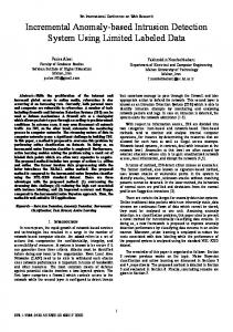
formally verify wireless systems [14] – [16]. Similarly, in existing literature, some attempts are made to formalize the communication protocols in mobile ad-hoc networks [17] – [19]. The formal verification of protocol can be helpful in devising its optimal design for resource stringent WSNs. Along similar lines, over the last decade, several attempts have been made to formally verify the security protocols for WSNs. Law et al. formally verified decentralized key management architecture for WSNs [20]. The architecture is based on two interoperable security realms: supervised and unsupervised. The CoProve tool is employed to verify the protocols. The protocol specifications act as input to the verifier. Then system scenario is analyzed to estimate the performance of protocol. In one of the recent works, Werner employs formal methods for model checking of energy consumption by sensor nodes in predefined settings [21]. Then brute-force algorithms are employed to search those paths, which lead towards optimum energy consumption. However, this approach is not suitable for probabilistic systems. A prototype for reliable model checking in WSN is suggested by Christian [22]. The temporal logic based model checking technique is employed for formal verification of traffic light synchronization protocol. The model is based on several abstractions for modeling variations in transmission errors, probability of packet collision, and radio range variations. The NuSMV model checker is used for verification of the formal model. Despite the presence of quite a few formally verified models in existing literature, the phrases “formal verification” and “anomaly detection” are still two distant terminologies. To the best of our knowledge, this is first attempt to formally verify the mobile agent based anomaly detection system in WSNs. The formal verification of anomaly detection system in designing phase can be helpful in eliminating redundancy and identifying missing requirements of the system. Therefore, in this study, we have formally verified the mobile agent based anomaly detection system in WSNs. The BTs are constructed to project the behavior of different components of the systems. We employed different tools form SAL environment to formally specify the model and then to verify its consistency and completeness. III. THE MAADS This section present a brief note on the Mobile Agent based Anomaly Detection (MAADS) system reported in [7]. In MAADS, the anomaly detection module is installed on Cluster Heads (CHs). In case of an abnormal behavior by any node in a cluster, CH triggers mobile agent that propagate to the suspicious node for further investigation. This approach provides two tiers security and eliminates the need of installing anomaly detection infrastructure on each sensor node. The anomaly detection has three components: Anomaly Agent, Coordination Unit, and Repository. The components of anomaly detection module in MAADS are depicted in Fig.1. • Coordination Unit: The coordination unit is responsible for overall management and coordination inside the anomaly detection module and also with
Fig. 1. Anomaly detection module in MAADS
•
•
other entities such as Base Station (BS) in the network. Upon arrival of each message, coordination unit send it to the repository for analysis. After that, repository sends analysis results to the coordination unit. The “normal” message is forwarded to the aggregation unit of CH. If received packet is anomalous then coordination unit triggers pre-defined corresponding action(s). Anomaly Agent: In case, the anomaly is node related, the mobile agent is triggered and transmitted to the suspicious node for further verification using victim node’s resource. The reason for further examination is that the anomaly might have actually caused due to network error or packet loss rather than due to an intrusion. Repository: The repository stores different tables related to anomaly detection. Some of the main tables are sensor nodes with their identities, audit record, normal profiles of sensor nodes, anomaly record, and action rules. The repository has the capability to store more tables as it is placed at CHs that are assumed as resource rich nodes.
The network model has three levels. The nodes with limited resources are deployed at leaf level and denoted as Sensor Nodes (SN).The CHs are resource rich nodes where anomaly detection module is installed. The BS is an overall controller of the network. The overall course of events of MAADS can be described as given below. • Æ In Event E0, the sensor reading, SNR, is collected from physical environment. • Æ In Event E1, the normal sensor reading, R, or anomalous reading R’, is sent to the CH. • Æ In Event E2, the CH performs analysis on / / Æ In Event E3, the aggregated or anomaly report is forwarded to BS. • Æ In Event E4, the BS perform decision on / . • Æ In Event E5, the report of is sent to the CH. • Æ In Event E6, the CH takes an action on the sensor node.
1002
8th IEEE Workshop on Network Security 2013
IV. MODEL FORMULATION The first formal step is the requirements translation from certain natural language into that of corresponding BTs. In this view, this section elaborates the functional requirements of MAADS. Then these requirements are translated into corresponding formal BTs. The Integrare tool is employed to build BTs [23]. During this stage, the inconsistencies are removed from the model. The next step is to methodically and incrementally construct the DBT of an overall system. The DBT is integration of different BTs. The DBT projects unified behavior of model and it should be able to satisfy all the functional requirements of the system. This phase is critical since individual components may project consistent behavior and the grafting of root state of one component with that of leaf state of other component may not be explicitly specified in initial functional requirements. Therefore, in this view, the pre and post conditions of each BTs are satisfied so that a consistent DBT can be constructed. This approach is ideal for detecting defects in early design stage of MAADS. Otherwise, missing requirements/ behavior may take system into halt state or give errors during state transition process.
anomaly detection module extracts parameters values from the data packet. The parameters values are compared with normal profile bounds of the sensor node. If comparison of parameters values is true, then sensor reading is normal and forwarded to the aggregation unit. If comparison is false, then mobile agent is triggered for the verification of suspicious behavior of the sensor node. Fig. 3 illustrates cluster head’s behavior projection for anomaly detection process. C. Sensor Node’s Behavior Projection for Verification Process The suspicious behavior of sensor node is specified in requirement three of the system. In this phase, sensor node receives mobile agent and stores it in its memory. To receive mobile agent sensor node needs to be in active state. This
A. Sensor Node’s Behavior Projection for Parameter Collection First requirement specifies the process of parameter collection on sensor node. In this process, sensor node goes into wake-up state at specific time and remains in sleep state if it is dead or faulty. After that sensor node collects parameters: sensor reading, timestamp, and resource status. The collected parameter values are then stored in sensor node’s stack memory and transmitted to the respective cluster head for further processing. After construction of initial BT, we identified following additional requirements to make anomaly detection system more robust. In active state, sensor node should check the battery level; if battery is below than a certain threshold level then it should go into dead state. On the other hand, if sensor node has battery above threshold level then it can perform the job of parameter collection. Similarly, the condition of memory access check is also included. If memory access is not successful then senor node is faulty. If memory access is successful then parameter values are stored in node’s stack memory. Furthermore, sensor node goes into sleep state after transmission of data packet. Fig. 2 illustrates the sensor node’s behavior projection for parameter collection process. Please note that in BTs, R1, R2, R3, R4, and R5 denote original behavior and R1.1+, R1.2+, R2.1+, etc., illustrate additional requirements identified through BTs during component behavior projection phase.
1003
[sleep]
SN
R1
??timer??
SN
R1
[wakeup]
SN
R1
R1.1 +
R1
R1.2 +
R1
R1.3 +
SN
SN
sensorReading resourceStatus
3
timeStamp
SN
SN
R1.1 +
R1.1 +
[collect]
2
?memAccessSuccess?
[active]
?batteryAbove?
1
R1
R1
B. Cluster Head’s Behavior Projection for Anomaly Detection Requirement two specifies the anomaly detection process at cluster head. In this course of action, cluster head receives data packet. If data packet is not received by cluster head within the specified time interval then sensor node is anomalous. This key requirement was missing in initial system requirements. The
SN
R1
SN ?batteryLow?
SN [dead]
SN [accessMem]
R1.2 +
R1.2 +
SN ?memAccessFail?
SN [dead]
SN [Msg1Sent]
SN [sleep]
Fig. 2. Sensor node’s behavior projection for parameter collection process
8th IEEE Workshop on Network Security 2013
SN
R1
[Msg1Sent]
SN
R1.3 R1 +
[sleep]
CH
R2
R2
R2
R2
CH
?Msg1Lost?
CH R2.1 +
[ADMactive]
CH [SNAnomalous]
CH [ExtractData]
R2
?Match?
CH
R2
CH
R2
>>collectedData
MobileAgent
result
report
sN'=sN_collect; pc1'=6; [] A6:pc1=6--> sN'=sN_accessMem; pc1'=7; [] A7:pc1=7 AND sN_memAccessSuccess--> [] A8:pc1=8--> extOutMsg_SN_collectedData'=true; pc1'=9; [] A9:pc1=9--> sN'=sN_Msg1Sent; pc1'=10; [] A10:pc1=10 AND cH_Msg1Recieved--> pc1'=11; [] A11:pc1=11 --> pc1'=12; [] A12:pc1=12--> cH'=cH_ADMactive; pc1'=13; [] A13:pc1=13--> cH'=cH_ExtractData; pc1'=14; [] A14:pc1=14 AND cH_MisMatch--> pc1'=15; [] A15:pc1=15--> extOutMsg_CH_MobileAgent'=true; pc1'=16; [] A16:pc1=16--> cH'=cH_MAsent; pc1'=17; [] ] END; % of MODULE END In above SAL specifications of integrated R1 and R2, PC denote program counter, A represent action. The Program Counter (PC1) has been initialized to 1. This program counter serves as guard to the first section, which starts at the root of the tree and includes all these states till the node just before the first event. The Action A1 indicates that the program moves to new state by incrementing PC1 to 2. A3 is the action that requirement one ends in other words PC2 has been assigned to the value 2. Once we transform DBT into that of corresponding SAL code, then range of analyses can be performed on formal specifications. One of the desired steps is to verify the correctness of different execution paths of the infinite state
1005
8th IEEE Workshop on Network Security 2013
system. Therefore, in next section, the correctness of all execution paths of the formal model of anomaly detection system is performed through LTL theorems.
th3: theorem behavior |G(sN_batteryAbove AND NOT (sN_memAccessSuccess)) => F(sN=sN_anomalous);
VI. ANALYSIS We now discuss the results gathered from formal verification of MAADS. In this process, several important theorems are analyzed that cover the main functionality of MAADS. Furthermore, the deadlock condition is also analyzed. The following LTL notations are used for analysis. • • •
Above theorem is proved on SALenv to confirm that a sensor node even with above battery threshold level can go into anomalous state if its controller is unable to access the memory. Like theorem 1, this condition also holds globally. th4: theorem behavior |G(sN_batteryAbove AND sN_memAccessSuccess AND NOT (cH_Msg1Recieved)) => F(cH=cH_SNAnomalous);
G(i): denotes that i is globally true. F(i): denotes that states i will be eventually true. X(i): denotes that there is/ are some successor state(s) after i.
At first, the normal path of the sensor node is defined. In other words, the theorem one defines that if all conditions are true then sensor node will be normal. These conditions includes battery check, memory access, correct message receipt by cluster head, anomalous observation detected by cluster head, successful memory access by mobile agent, successful receipt of mobile agent execution result by cluster head, and result indicating sensor node as normal. These conditions must hold globally in the network for every sensor node to be a normal node. th1: theorem behavior |G(sN_batteryAbove AND sN_memAccessSuccess AND cH_Msg1Recieved AND cH_MisMatch AND sN_MAsaved AND cH_ResultRecieved AND cH_resultTrue) => F(sN=sN_Normal); Theorem one was executed on SAL code of MAADS. The theorem is proved without any counterexample. It proved that the sensor node can enter into normal state if it passes all conditions. After verification of the normal behavior of sensor node, the correctness of the model is verified for all possible anomalous states of the system. The second LTL theorem states the condition when sensor node eventually goes into dead state. The condition is based on battery level. If sensor node has battery level above predefined threshold then it will enter into dead state.
th5: theorem behavior |G(sN_batteryAbove AND sN_memAccessSuccess AND cH_Msg1Recieved AND NOT(cH_MisMatch)) => F(cH=cH_Aggregate); th6: theorem behavior |G(sN_batteryAbove AND sN_memAccessSuccess AND cH_Msg1Recieved AND cH_MisMatch AND NOT(sN_MAsaved)) => F(cH=cH_SNAnomalous); Theorems four, five, and six are proved without counterexamples. These theorems are proved to verify that the sensor node can still be anomalous if its battery is above threshold level, memory is accessible, anomaly detection module identify current observation as anomalous and transmit mobile agent but sensor node’s memory is not reachable.
th2: theorem behavior |G(NOT (sN_batteryAbove)) => F(sN=sN_dead); This satisfies the anomalous behavior of sensor node with respect to the battery level. The sensor node will be dead if its battery is not above certain threshold level. The next step is to verify the anomalous behavior of sensor node with respect to its memory access status.
1006
th7: theorem behavior |G(sN_batteryAbove AND sN_memAccessSuccess AND cH_Msg1Recieved AND cH_MisMatch AND sN_MAsaved AND NOT (cH_ResultRecieved)) => F(sN=sN_SNAnomalous); th8: theorem behavior |G(sN_batteryAbove AND sN_memAccessSuccess AND cH_Msg1Recieved AND cH_MisMatch AND sN_MAsaved AND cH_ResultRecieved AND NOT (cH_resultTrue))
8th IEEE Workshop on Network Security 2013
=> F(cH=cH_SNAnomalous); Theorems seven and eight are also proved without any counterexamples. The proof of these theorems further validates that the sensor node can still go into anomalous state if cluster head does not receive any result of the mobile agent execution or even the successful execution of mobile agent confirms the anomalous status of node. Above theorems (2 to 8) validates only those paths where anomaly detection system makes no false negative decisions. However, in some situations, the anomaly detection system must have no false positives to detect anomalous sensor nodes. Therefore, in such situations, theorems should be proved through counterexamples (or counter paths). Below, 7 theorems (9 to 15) are defined to further verify the functioning of anomaly detection system. th9: theorem behavior |G(NOT (sN_batteryAbove)) => F(sN=sN_Normal); As per theorem 9, it must be globally true that the sensor node can be in normal state even with battery level below a certain threshold. However, the expected result by anomaly detection system is to declare sensor node as anomalous in such situations. The counterexample given below indicates that the above LTL theorem cannot be proved. Counterexample for th9: ======================== Path ======================== Step 0: --- Input Variables (assignments) --cH_Msg1Recieved = false sN_batteryAbove = false sN_memAccessSuccess = false cH_MisMatch = false cH_resultTrue = false cH_ResultRecieved = true sN_MAsaved = true extInMsg_SN_timer = false extInMsg_CH_collectedData = false extInMsg_SN_MobileAgent = false extInMsg_CH_result = false extInMsg_BS_report = true --- System Variables (assignments) --extOutMsg_SN_collectedData = false extOutMsg_CH_MobileAgent = false extOutMsg_SN_result = false extOutMsg_CH_report = false sN = sN_sleep cH = cH_Aggregate bS = bS_active pc1 = 1 ------------------------
Transition Information: (module instance at [Context: UsmanSingleV1, line(217), column(14)] (label A1 transition at [Context: UsmanSingleV1, line(24), column(3)])) -----------------------Description of steps 1 to 4 is not provided here -----------------------Step 5: --- Input Variables (assignments) --cH_Msg1Recieved = true sN_batteryAbove = false sN_memAccessSuccess = false cH_MisMatch = true cH_resultTrue = true cH_ResultRecieved = true sN_MAsaved = false extInMsg_SN_timer = false extInMsg_CH_collectedData = false extInMsg_SN_MobileAgent = false extInMsg_CH_result = false extInMsg_BS_report = true --- System Variables (assignments) --extOutMsg_SN_collectedData = false extOutMsg_CH_MobileAgent = false extOutMsg_SN_result = false extOutMsg_CH_report = false sN = sN_dead cH = cH_Aggregate bS = bS_active pc1 = 0 This counterexample is based on 6 steps (from 0 to 5). The system is initialized by assigning input and system variables in the counterexample. The program eventually reaches at condition (NOT (sN_batteryAbove)). Then it alerts the anomaly detection module at cluster head to declare node as anomalous. As per theorems ten, eleven, and twelve, it must be globally true that the sensor node can still be in normal state after satisfying all conditions including not declared as anomalous by cluster head even after identifying anomalous observation. However, theorem proving produces counterexamples indicating theorems are not proved. Thus these paths are invalid. th10: theorem behavior |G(sN_batteryAbove AND NOT (sN_memAccessSuccess)) => F(sN=sN_Normal); th11: theorem behavior |G(sN_batteryAbove AND
1007
8th IEEE Workshop on Network Security 2013
sN_memAccessSuccess AND NOT (cH_Msg1Recieved)) => F(sN=sN_Normal); th12: theorem behavior |G(sN_batteryAbove AND sN_memAccessSuccess AND cH_Msg1Recieved AND NOT(cH_MisMatch)) => F(sN=sN_Normal);
Fig. 7. Deadlock state check
Similarly, theorems thirteen, fourteen, and fifteen defines it must be globally true that the sensor node is in normal state after passing all conditions and even if cluster head does not receives true status of sensor node after execution of mobile agent. Again, sal-smc produces counterexample indicating these paths are invalid and theorems cannot be proved. th13: theorem behavior |G(sN_batteryAbove AND sN_memAccessSuccess AND cH_Msg1Recieved AND cH_MisMatch AND NOT(sN_MAsaved)) => F(sN=sN_Normal); th14: theorem behavior |G(sN_batteryAbove AND sN_memAccessSuccess AND cH_Msg1Recieved AND cH_MisMatch AND sN_MAsaved AND NOT (cH_ResultRecieved)) => F(sN=sN_Normal);
MAADS. First, we validated normal path of the sensor node, i.e. if all conditions expressed in theorem 1 holds then sensor node is normal. The proofs of theorems 2 to 8 validates those situations where MAADS makes no false negative decision. Similarly, the MAADS must not have any false positives to detect anomalous sensor nodes. This is validated in theorems 9 to 15 through counterexamples. The counterexamples demonstrate that the paths are invalid thus theorem cannot be proved for such situations. During the course of formal analysis, we validated all state transitions of anomaly detection system through LTL theorems. The analysis demonstrates that the state transitions (BTs) satisfy both situations where MAADS have no false positives and false negatives. The analysis further revealed that there is no loop or deadlock in the system design. This validates the completeness and consistency of the MAADS. VII. CONCLUSION
th15: theorem behavior |G(sN_batteryAbove AND sN_memAccessSuccess AND cH_Msg1Recieved AND cH_MisMatch AND sN_MAsaved AND cH_ResultRecieved AND NOT (cH_resultTrue)) => F(sN=sN_Normal); One of the key desired properties of a finite state system is that it should not have any deadlock state. The SAL 3.0 distribution has an auxiliary tool, sal-deadlock-checker, which detects deadlocks in finite state system [24]. The sal-deadlock-checker is employed to check the deadlock state and we found no deadlock state in the system. A snapshot of deadlock state checking process is given in Fig. 7. We performed the formal verification of MAADS. The formal verification, carried out in SALenv, is based on the analysis of several LTL expressions demonstrating working of
Traditionally, complex systems are built to satisfy their requirements. On the other hand, behavior trees build systems out of their requirements. The Behavior Trees are appealing because of their ability to detect defects at the early stage of system’s life cycle, instead of identifying and removing them after implementation. This approach is very useful for WSNs because of their low resources. A poorly and non-validated system design may put adverse effect on WSN resources, or even in worst case, the anomaly detection system may go into halt-state. Therefore, in this study, we have formalized and validated mobile agent based anomaly detection system for WSN. The behavior information is extracted from system’s requirements. Then BTs are constructed for behavior projection of each individual component of the system. We integrated several BTs into DBT that projects a unified behavior of the overall system. This helped us in removing ambiguities/ incompleteness in the design of mobile agent based anomaly detection model. We then validated the formal model through SAL tool. The analysis carried out through LTL theorems, demonstrates the completeness and consistency of the system. In future work, we aim to carry out formal verification of mobile agent based anomaly detection system against different attacks and fault based anomalies in sensor nodes. ACKNOWLEDGMENT The Authors wish to acknowledge Mr. Khosrow Ramezani for his critical appraisal of parts of this study.
1008
8th IEEE Workshop on Network Security 2013
REFERENCES [1] M. Usman, V. Muthukkumarasamy, X.-W. Wu, and S. Khanum, “Securing Mobile Agent Based Wireless Sensor Network Applications on Middleware” IEEE 12th International Symposium on Communication and Information Technology (ISCIT), pp. 707-712, Australia, 2012. [2] M. Usman, V. Muthukkumarasamy, X.-W. Wu, and S. Khanum, “Anomaly Detection in Wireless Sensor Network: Challenges and Future Trends” Book chapter, Security for Multihop Wireless Networks, Auerbach publications, Taylor & Francis Group, USA, 2013. (In press). [3] C. Krugel and T. Toth, “Applying Mobile Agent Technology to Intrusion Detection” Proceedings of ICSE Workshop on Software Engineering and Mobility, pp. 1-5, 2001. [4] O. Kachirski and R. Guha, “Effective Intrusion Detection using Multiple Sensors in Wireless Ad hoc Networks” Proceedings of 36th Annual Hawaii International Conference on System Sciences, pp. 57–65, 2003. [5] M. Ketel, “Applying the Mobile Agent Paradigm to Distributed Intrusion Detection in Wireless Sensor Networks” 40th IEEE Southeastern Symposium on System Theory, pp. 74-78, 2008. [6] S. I. Eludiora, O.O. Abiona, A.O. Oluwatope, S.A. Bello, M.L. Sanni, D.O. Ayanda, C.E. Onime, E.R. Adagunodo, L.O. Kehinde, “A Distributed Intrusion Detection Scheme for Wireless Sensor Networks” IEEE International Conference on Electro/Information Technology, pp. 1-5, 2011. [7] M. Usman, V. Muthukkumarasamy, X.-W. Wu, and S. Khanum, “Wireless Smart Home Sensor Networks: Mobile Agent Based Anomaly Detection” 9th IEEE conference on Ubiquitous intelligence and Computing (UIC), pp. 322-329, Japan, 2012. [8] P. C. Olveczky and S. Thorvaldsen, “Formal modeling, performance estimation, and model checking of wireless sensor network algorithms in Real-Time Maude” Journal of Theoretical Computer Science, Volume 410, Issue 2-3, pp. 254-280, 2009. [9] R. G. Dromey, “From Requirements to Design: formalizing the key steps” Proceedings of 1st International Conference on Software Engineering and formal methods, pp. 2-11, 2003. [10] L. Moura, S. Owre and N. Shankar, “The SAL Language Manual” SRI International Rev. 2, 2003. [11] E. Sithirasenan, S. Zafar, V. Muthukkumarasamy, "Formal Verification of the IEEE 802.11i WLAN Security Protocol", In Proceedings of IEEE Australian Software Engineering Conference, pp. 181-190, 2006. [12] K. Ramezani, E. Sithirasenan, V. Muthukkumarasamy, "Formal Verification of the Coordinated Robust Authentication Protocol for Wireless Networks", In Proceedings of 12th IEEE International conference on Trust, Security, and Privacy in Computing and Communications (IEEE TrustCom-13), 2013. [13] C. H. West, “General technique for communications protocol validation” IBM Journal of Research and Development, Volume 22, Issue 4, pp. 393, 1978. [14] E. S. M. Merro, “A timed calculus for wireless systems” In FSEN, Lecture Notes in Computer Science, pp. 228–243, 2010. [15] S. Nanz, “A framework for security analysis of mobile wireless networks” Theoretical Computer Science, pp. 203–227, 2006. [16] N. Mezzetti and D. Sangiorgi, “Towards a calculus for wireless systems” Electronic Notes in Theoretical Computer Science, pp. 331–353, 2006.
[17] S. A. A. Singh and C. R. Ramakrishnan, “A process calculus for mobile ad hoc networks” Lecture Notes in Computer Science, Springer, pp. 296–314, 2008. [18] J. C. Godskesen, “A calculus for mobile ad hoc networks” Proceedings of 9th International Conference on Coordination Models and Languages, Lecture Notes in Computer Science, Springer, pp.132–150, 2007. [19] M. Merro, “An observational theory for mobile ad hoc networks” Proceedings of 23rd Annual Conference on Mathematical Foundations of Programming Semantics, pp. 275–293, 2007. [20] Y. W. Law, R. Corin, and S. Etalle, “A formally verified decentralized key management architecture for wireless sensor networks” Personal wireless communications, Lecture notes in computer science, Springer, pp. 27-39, 2003. [21] F. Werner, “Applied Formal Methods in Wireless Sensor Networks”, Doctoral Thesis, pp. 177, 2009. [22] A. Christian, “Reliable Model Checking for WSNs” Proceedings of 8, GI/ITG KuVS Fachgespräch "Drahtlose Sensornetze", Hamburg-Harburg, August 2009. [23] L. Wen, J. Seagrott, and G. Dromey, “A collaborative environment for Behavior-Oriented Design” Cooperative Design, Visualization, and Engineering, pp. 122-131, 2007. [24] B. Dutertre, “SAL 3.2 Binaries without Yices” retrieved from http://sal.csl.sri.com/download.shtml, 2013.
1009