Formalization of UML Clas s Diagram Using Description Logics Wan M.N. Wan-Kadir l and Radziah Mohamad2
Lusiana Efiizoni
Teknik Informatika STMIK-AMIK Riau - Pekanbaru JI. Purwodadi Indah Km . l 0 Panam Riau, Indonesia e-mail :
[email protected]
Software Engineering Department Faculty of Computer Science and Information Systems Universiti Teknologi Malaysia 8 1 300 UTM Skudai, Johor, Malaysia e-mail :
[email protected] .
[email protected]
A bstract-Unified Modelling Language (UML) i s as a standard object-oriented modelling notation that is widely accepted and used in software development industry. notation is informally defined in
In general, the UML
term
of natural
language
description (English) and Object Constraint Language (OCL) which makes difficult to formally analyzed and error-prone. In this paper, we elucidate the preliminary result on an approach to formally
define
UML
class
diagram
using
logic-based
representation formalism. We represent how to define the UML class diagra m using Description Logics (DLs).
Keywords-component; formalization;
UML
class
diagram;
logic-based; description logic
1.
INTRODUCTION AND MOTIVATION
The emergence and development of new methodology has a positive impact to software engineering community as an attempt to reduce the complexity and diversity of software development process. Currently, object-oriented (00) approach is more popular used in software specification due to relative easy to use and understand that is graphically presented. Most of 00 approach is informally defined and it has any restrictiveness such as not support the rigorous analysis and its notation is limited in expression. One example of the 00 language is Unified Modelling Language, UML in shortly. UML is as a standard 00 modelling notation that is widely accepted and used in industry application. UML is a graphical model ling language with the various type models can be used in specification, visualization and documentation phase in software development process. The UML specification is defined by metamodelling approach might capture the abstract syntax, concrete syntax and semantics of UML. The current work, the abstract syntax of UML is described by UML class diagram meanwhile the concrete syntax and semantic of UML notations define a model ' s meaning in a combination of the Natural Language (English), and Object Constraint Language (OCL). Either these languages are not sufficiently to state the semantic of UML notation or support to analyze the UML model s. These languages always need to be combined with others to state the complex constraints [ 1 ] . In addi tional, most of UML notation is informally defined so i t makes error-prone and difficult to analyze formally. This work is to provi de the precise semantic i . e. UML class diagram formally.
978- 1 -4244-6 7 1 6-7/ 1 0/$2 6 . 00mo 1 0
This paper shows the preliminary result based on an approach to formally define UML class diagram. UML class diagrams are a diagram type that well-established in UML model and play an important role in analysis and complexity of designed system. UML class diagram is used to specify the static structure of the software system which is under study. In order to analyze the UML class diagram, a formal and sound foundation is required. We are interested to explore logic-based representation formalism (i. e Description Logics) to carry out the formalization of UML class diagram. A description Logics (DLs) [2] can support the specification phase in software development. Based on the literature perspective, DLs is well suited to express the design models completed with a declarative nature. This paper focuses on how to define the UML class diagram using DLs. The structure of the rest of this paper is as follows. Section 2 di scusses the related work. In section 3 of this paper presents a brief review of the description logics. Section 4 descriptions the preliminary result which depicts the basic conceptual framework for formalization and presents the UML class diagram formalization result. Finally, section 5 discusses conclusion and future work. II.
RELATED WORK
UM L is de-facto standard for 00 modelling [3-7] in industry application to develop a software system. UML is based on graphical notation that is supported by visual syntax and expressiveness which is easy to understand. However, it lacks of precise to define the semantics and hard to convince that the end design is consistent, unambiguous and complete. As a result, several works have been done to remedy this problem. For example, Object Constraint Language (OCL) tried to reduce them [4, 8, 9] but OCL is not enough to do it because OCL constraint cannot be executed. Further more it is difficult to be checked and detected so it gives problem in development and maintenance phase [8]. In addition, the description of UM L's syntax can be described using OCL. Unfortunately, it has no complete and precise semantic specifi cation which gives confusion and complicated problems during a model analysis. Currently, researchers frequently worked to obtain the high expressiveness of UM L by formalization. According to Zhihong and Mingtian [ 1 0], there are two obj ective why
I EEE
1 1 68
formalization is needed in UML construction . Firstly, the precise formalization can be use to formally explain the semantics of UML. This objective, can give the similar perception about UML. Secondly, the formalization can produce an automatic reasoning procedure which helps us in checking UML. To reach the first obj ective, many formalizing techniques have been proposed. Formal Method (FM) may be considered to formalize UML relating to both UML's syntax and UML 's semantics or individually. FM is an appropriate technique and a precise way to produce software. The current FM that was applied in this work such as Z notation [ 1 , 1 1 - 1 3], B notation [ 1 4, 1 5] , VDM++ [9], PVS [3 , 1 6], FOL [ 1 7] and DLs [ 1 0, 1 8, 1 9] . However, most of these works is not sufficient to provide a formal basic for the abstract syntax and semantics of notation. The literature perspective mentioned that FM is an approach that difficult to understand and expensive to use [ 1 4, 1 5 , 20], but if FM is integrated with 00, it can reduce difficulty in the usage. Using 00 modelling allows reducing the semantics gap between the certain problem domain and the evolving structural models. Unfortunately, the existing tools and current work is still limited and ineffective [9] . The various type of UML diagrams used in formalization is class, interaction, state chart, use case, object, and collaboration as well as sequence diagram. In this paper only considers using a class diagram and DLs notations to formalize the UML class diagram. UML class diagram is choice based on the following reasons: 1) Class Diagrams (CDs) play a prominent role in analysis and design of a complex system. During analysis, classes refer to people, place, event, and things which the system will be about to capture information later. While, implementation specific artefacts like windows, forms, and other object are used to build the system during the design and implementation. 2) CDs are the most important structure diagram and well established. It is able to describe the information on the interest domain in term of object organized by classes and relationship among them. CD is also a formal way of representing objects that is used and created by business roles. 3) A CD is core of modell ing element which is used in behavioural diagram and the abstract of UML syntax is explained by CDs. Whilst, DLs is considered based on the following reasons: I) It is suited to provide the knowledge for the static structure of software application . 2 ) I t is based on formal well-studied and understood semantics i.e. descriptive semantics. 3) There are still wide developments in formalization of UM L class diagram in which many elements are not defined by DLs yet. 4) Its community is wel I organized and still at infancy stage. III.
A BRIEF REVIEW OF THE DESCRIPTION LOGICS
Description Logics (DLs) [2] is an approach that based on the mathematical logic which can be used to formalize the
knowledge representation. DLs have objectives to characterize and motivation the fields in term of application knowledge to represent a structured into well-understood way. DLs are also able to represent the structural knowledge of an application domain through a knowledge base including a terminology and a world description. The main domain of DLs is interested on concept (unary predicate), roles (binary predicate), and individuals (constant) respectively [2] . The basic formalism of a DL system consists of three components [2 1 ] : 1 ) Constructors representing concept and role, 2) Knowledge base (KB) consisting of the TBox (terminology) and the Abox (world description). The Tbox presents the vocabulary of an application domain, while the Abox includes assertions about named individuals in terms of thi s vocabulary, 3) Inforences as reasoning mechanisms of Tbox and Abox. A.
Notational Conventions
The basic formalisms of DLs are formed based on the following components such as: the formalism for describing concepts or the description language, define both terminological (TBox) and assertion (ABox) formalism, and the reasoning formalism. Elementary descriptions of description language are atomic concepts and atomic roles. Concept constructors can be applied to build the complex descriptions. In abstract notation, A and B are used to define atomic concept; C and D for concept description ; R and S are assumed as roles and for functional roles (feature attribute) the letter/. g. In defining the concept name by DLs, it is started with an uppercase letter and then followed by the lowercase letter (e.g., Human, Male). Roles name (also functional ones) starts with a lowercase letter (e.g., hasChild, marriedTo) and individual names are all uppercase (e.g., CHARLES, MARY). One example of description language is cAL (A ttribu t e Languag e) and others are extension of cAL. the concept descriptions of cAL are formed based on the following syntax rules: C, D
�
A
T .1
I ; Atomic concept
I;;
Universal concept Bottom concept
I ; Atomic negati on C n D I ; Intersection
..,A
'rIR. C 3 R . T;
L Value restriction
Limited existential quantification
For Example, if we suppose that Female and M o t her are atomic concepts and hasChild is atomic role. Using the universal concept ( T) , we can form the concept Female n 3 hasCh i l d . T and M o ther n 'rIhas C h i l d . Female . These concepts describe that Female has a child and mother all of whose children are female. Using the bottom concept (.1) , we can form the concept a mother wi thout a child by M o ther n 'rIhasChild . .1.
1 1 69
Beside description language, terminology is also as basic formalism of DLs. In most general, terminological axioms have the form: C !; D , (R !; S) are called inclusions or C == D, (R == S) are called equalities, where C, D are concepts (R, S are roles). The semantics of axioms is defined as an interpretation I satisfies and inclusion C !; D if C I S; D I and it satisfies an quality C == D if C I D I . DLs are able to perform specific kinds of reasoning. The different kinds of reasoning performed by DLs system are defined as logical inferences. =
B.
In this section, we briefly describe the syntax and semantic of the DLs. The concept descriptions are formed according to the following syntax: TABLE I S YNTAX OF C ONCEPT C ONSTRUCTOR
Constructor
Intersection Union Negation Value restriction Limited existential quantification Existential quantification At-least number restriction At-most number restriction Exact number restriction Qualified at-least restriction Qualified at-most restriction Qualified exact restriction Same-as, agreement Role-value-map Role fillers
Concrete Syntax TOP BOTTOM (and C , . . . C.) (or C, . . . C.) (not C) (all R C) (some R) (some R C) (at-least n R) (at-most n R) (exactly n R) (at-least n R C) (at-most n R C) (exactly n R C) (same-as u, u,) (subset R, R,) ( fi l l ers R I , . . . !.)
One-of
(one-of I , . .1.)
Top Bottom
S OME
Constructor Top Bottom Intersection Union Negation Value restriction Existential quant. Unqual i fi ed number restriction Qual ified number restriction Rol e-valuemap Agreement and di sagreement Role name Inverse Composi tion Rol e Conj. Role H ierch.
DLs
Abstract Syntax
� C n ... n Cn C u ... u (',.
..., C 'IR. C 3R. T 3R. C > nR nR C < nR C = nR C u = 1!2 R, 6; R, 3 R . /, n . . . n 3R.lR I U UI
TABLE 2 R OLE CONSTRUCTOR
Semantics
..., C 'IR . C
f),1 (i) cl n DI CI U DI f),I I CI {a E f),1 1 'lb. (a, b) E RI .... b E CI }
3R. C
{a E f),1 1 3 b . (a, b) E RI A b E CI }
R R RS R, n R, R, C R,
•..
C ONCEPT AND
Syntax
?nR ::; n R =nR ?nRC ::; n R C =nRC R r;;; S R = S u, = u2 u, *' U2
The Formalization Framework
The proposed approach consists of a conceptual framework and its supported theoretical foundation. In general speaking, a framework is defined as a basic foundation of conceptual structure that provides a guideline in constructing of something that develops the defined structure into something useful.
T
T
� c n D CUD
PRELIMINARIES
In thi s section, the proposed approach is presented. Section A presents the formalization framework as foundation how to formalization must be done. Section B is brief introduction and about UML Class diagram. Element of UML class diagram will be shown in section C. Finally, the application of the proposed approach will be represented by a simple example. A.
Syntax and Semantics ofDLs
SOME
IV.
{a E f),1 1 b E f),1 1 (a, b) E R I } I? n} {a E f),1 1 b E f),1 1 (a, b) E R I } I::; n} fa E f),1 1 b E f),1 1 {a, b) E RI l l = n} {a E f),1 1 b E f),1 1 (a, b) E RI A b E CI } I ? n} {a E f),1 1 b E f),1 1 (a, b) E RI A b E CI } I::; n} {a E f),1 1 b E f),1 1 (a, b) E RI A b E el} 1 = n} {a E f),1 1 'lb. (a, b) E RI .... (a, b) E Sl } fa E f),1 1 'lb. (a, b) E RI ... (a, b) E SI } {a E f),1 1 3b E f),1. u{ (a) = b = u{ (a) } {a E f),1 1 3b, . b2 E f), 1 . ul ( a ) = b, *' b2 = ul ( a )} RI I (b, a) E f),1 X f),1 1 ( a , b ) E RI l f ( a, c) I 3 b . ( a , b) E RI A (b, c) E SI} Ri n R� RI r;;; R�
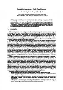
Figure I . A Conceptual Framework for Formalization
Figure 1 shows a conceptual framework formalization that become as foundation in this work how to formalize the UML class diagram using one of family of logic-based approach i.e. Description Logics (DLs). DLs will be used to define the syntax and semantic of elements of UML class diagram which refers to table I and 2 trough the formalization process. The formalization is expand based on the previous work [7, 1 9] and its result helps to make the same perception e.g. consistence understanding of elements of UML class diagram. B.
UML
Class Diagram
This work concentrates on UML class diagram for the conceptual perspective. The formalization of UML class diagram is based on formal approach taking advantages from both a conceptual modelling diagram (UML) and DLs. Logic in formalization is basically considered as a set of reason and consist of: a given precise semantics, formal verification, and virtually unlimited expressiveness. Class Diagram is a static diagram or model that shows the classes and relationship among classes that remain constant in the system over time. A class diagram depicts classes of the objects under study is completed with the common feature and the relationship among them. The common feature of class diagram is comprise the structural feature (i .e. attribute and association ends) and the behavioural feature (i.e. operation). The following sections wi ll present the elements of UM L class diagram as shown in figure 2.
1 1 70
2)A ttribute
Attributes are presented in the UML 2.0 metamodel by property 'structural feature' that describe the state of an obj ect. Let a be an attribute of a class C with type T , an optional multiplicity i. . j . Thi s means that an attribute is denoted by a name, possibly followed by a mUltiplicity and the associated type of the attribute as follows: Visibility name: type mulliplicily
Figure 2. UML C lass Diagram metamodel
C. Element of UML Class Diagram Formalization
UML class diagram depicts a structural aspect of the model of a system in graphic. Thi s graphic shows what conceptual 'th ings' exi st in a system and what relationships exist among them. In this section, the Class Diagram (CD) formalization for the structure syntax as below: l) Classes
. . Classes in UML model represent a set of obj ects or Its instance in which the obj ects belong to. A class called instancesis the class forming instantiation or extension of the class, with the common feature (see Figure 2). Properties in UML 2 . 0 contain two distinct notations: attributes and association ends. A property owned by a class is attribute, whilst a property owned by an association is known association ends. A class is a main block of UML class diagram which is used to store and manage information. Each class is. graphically depicted using three compartments with class ' name at the top, attributes in the middle, and operation at the bottom (see figure 3). An UML class C is represented by atomic concept C. The above description describes that a class is generally composed a set of attributes and operations denotes simplify as C ( Cn, ai' aj ' Oi' ) ' where: • Cn denotes class name, the class name has to be unique in the whole diagram. • ai is a set of attribute name of the class, for i= l . . n. • a1· is a set of attribute type of the class, for j= l . . .n. • 0i is a set of operations of a class, for i= 1 . .n =
!;;;
'Va (x) . T (y)
Visibilily indicates whether an attribute IS public or private. • Name denotes the name of the attribute. • The Iype of the attribute specifies which kinds of values or object an attribute can contain. • The mnlliplirity of an attribute indicates how kinds of values or obj ect may fill the attribute. The attributes of a class denote by DLs assertion as (without the definition of visibility) :
'Vx, y. C(x) !;;; 'Va(x) . T(y)
It has attributes name ax and type Ty . Attribute name must be unique only in the class it belongs to, possibly ;ultiplicity (i.e. implicit or explicit). Implicit multiplicity is assumed to be 1 . . . 1 (i .e. the attribute is mandatory and single value), and an explicit multiplicity with a minimal and maximal number of value e.g. 1 . . . * . Multiplicity is a constraint o n the number o f instances of one class that may be connected to the other class instance. An assertion for multiplicity [i . . j] states that for a associated to each instances of C, at least i and most j instances C '. To state the multiplicity [i . . . j]of a that is: a
'Vx, y. C (x)
!;;;
'Va (x) . T (y)
n
3 a(x)
n
(i
::;;
(a(x)} ::;; j)
Note that, if j is * then the second conjunction can be omitted and if the multiplicity is [0 . . . *] then the whole assertion can be ignoring but if multiplicity is [ 1 . . . 1 ], the first conjunction can be omitted. For example by refer to Figure 3, it is possible to write: A ccount/ tern � 'VNo tes. s trinB
n
3 N o tes
n
( S l N otes)
3) Operation
A class, we state in DLs assertion as: 'Vx, Y. C (x)
•
n
P (x)
Where: c ex) : name x of a class; a(x) : name x of attribute, T (y) : type of attribute, and P (x) : name x of operation of a class.
Operation is actions or functions from the object of class to which the operation is associated. The full UML syntax for operation is: \'isibilily n a m e (pa ra melcr-lisl): rcl nrn-Iype
The
denotes the name of operation and is a string. is the list of parameter of the operation. The reln nHype is a comma-separated list of return types. If an operation has no parameter(s), the parentheses are still shown but are empty. In generally, operations have names and parameters P ('VP has a name and a type). An operation of a class can be stated by mean of DLs such : The
Accountltem
oles : siring '-----�-=_+> O rder : inl +OrderBalance : floal +OrderSlalus : siring IlemBaia nceO : floal : s�lr�in��������---� r�::::���������
'Vx, y. C(x) !;;; 'Vp[(x),y . Ri (y)
Parameter list
Figure 3 . Common Properti es ofa Class in UM L Class Diagram
name
parameler-Iisl
for i,j
E 1
n
(i ::;; p[ (x).y 2:. j)
... n
1 171
Where C (x) denotes the name of a class, R i s return values or type of result belonging R1 ... Rn, fx is the operation ' s name Py is y parameter belonging to the classes P1 .. Pn . For example (based on Figure 3): A ccountltern
!;;; V PGetOrderld( ) . s tring
n (:5
1 PGetOrderld O )
objects of the subclass. Note that every instance of each subclass is also instance of the super class. If an UML class C2 generalizes a class Cl , we can express this in DL assertion : C1 c C2 or C1 !; C2 means every properties of C2 are also the properties of C1 but C1 C2 • Generalization in UML can be grouped into a class hierarchy, as shown in figure 6.
4)Assocation and Agregation
A relationship between two or more classes (or a class and itself) in UML class diagram i s represented by an association. An association is labelled using a verb phrase A or a role name r that described properties of the association (e.g. attribute, operation and others). In UML, an association is a relation between instances of two or more classes as shown in figure 4(a). An association between two classes is a property of both classes. � . .d a. b � 1 ., 2 [§J 0 m1.rn2 . C2 C2 C1 C1
{dl�joint.complotc}
Figure 6. A class hierarchy in UML
A Class hierarchy in UML can be expressed in FOL assertion:
r1
A
r2
A
Figure 4. Binary association (a) and aggregation (b) in UML Figure
5
presents multiplicities of binary association, in DLs will be
stated: A !;;; 3 r1 , C1 n 3r2 , C2 T !;;; VA . C2 n VA- , C1 To state that each instance of C1 is connected by A to at least a and at most b with r1 and each instance of C2 is connected by A- to at least a and at most b VX1 . C1 (X1 ) !;;; ( a :5 {r1-. A } :5 b ) V X2 , C2 (X2 ) !;;; ( c :5 {rz-A - } :5 d)
Example of association :
I
Company
11-------,----'·-·----il employee
employer
Person
1
Job
C
6) Constraint
job !;
3 employer.
Company
n 3 employee. Person
T !;;; Vjob. P erson n Vj o b - . Company Person !;;; ( 1 :5 employe e - .job- :5 1 ) Company !;;; ( ;::: 1 employer- .job)
n-ary association A among classes C1 . . . Cn is a n-ary predicate in FOL. We need to define the component of the predicate must belong to correct classes as:
U
C2
U
... U Cn
VX' Ci (x) � , Clx) for i,j E 1 . . . n where i "* j Completeness is a condition where each instance of superclass is also instance of at least one of the subclasses. In DLs is formalized as: 7) Composition Composition is an instance of a class that become a part of instance of another class. It means that sometimes an object is made up of other object. Composition is depicted with a fulfil diamond. In DLs assertion is stated as follow:
Vx. C2 (x)
C (x)
E
U
Vx. ,C (x)
C2 (x)
E
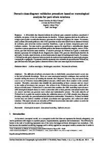
D. A Simple Example
In this section , a simple example (see Figure 7) is shown to illustrate the whole formalization . In Class Diagram, there are six classes (Student, Undergrade, Graduate, Class, Lecturer, and Course) and one generalization which can be stated in three assertions as follow: Student
V xI , ... , xn - A (xl , ... , xn ) !;;; CI (XI ) n , . . . , n Cn (xn) .
+getEmailO : chaf ffe�sterForaass() . int
vxl · C1 (Xl ) !;;; (;::: 1A)
I
I
UnderGrade
�
I J
5) Generalization and Inheritance
�artjeS : Char
In UML, generalization depicts that one class is identified as the super-class and the others as subclasses of it. The properties and operation of the super class are also valid for
j+addP.r1yO . char I
I L
1
1 .'alSlr.ant
,· 1
Graduate
I j
1+·p�yforR"'J char I
Figure
Class
rtglStertic
Name : char birthday : int emai1 : char
An aggregation A bases on the figure 4 (b) without mUltiplicities, we formalize using DL as fol low: VX2 • Cz (Xz) !;;; ( 1 :5 A - :5 1 )
Cl
!;
{l. . n}
E
Constraint can be used to add information (i.e. disjoint and complete) in UML' class hierarchy as additional properties of a class, between each child classes and parent class. Disjointness is a condition where the different subclasses cannot have common instance which is stated in DLs assertion as fol lows:
Figure 5. An example of binary association
In DLs can be written as follow:
for i
Vx. Ci (x) !; C (x)
n
7.
Gode : char Semester : int Status : char
1.'-
L. I L' � :' 'h'' +getSt.lus() · int
Course
CoursE;
Title : char Description : char Credll : int +getcoUfseO . char
.
lech.-er
Name : char 10 : inl
+getledurerO char
A si mple example of UML Class Diagram
1 1 72
Definition of properties of Student ' s class capture attributes and
[4]
operation as follows :
Vx, y. Student(x) � Vname(x) . char(y); Vx, y. Student(x) � Vhirthday(x) . int(y) ; Vx, y. Student(x) � email(x) . char(y) ; Student � V PgetEma i l O . c har n (::5 1 PgetEmaiI O ) ; Student � V PregisterforclassO . int n (::5 1 PregisterforclassO )
of the UML and OCL meta-model in I sabelle/HOL," Lahore, Pakistan, 2007. [5]
Association of both classes
between
Singapore, 2008, pp. 477-482. [6]
classes):
74-84. [7]
V.
CONCLUSION AND FUTURE WORK
This paper has shown the formalization of element of UML class diagram in term of specified formal logic i.e. Description Logics (DLs). Through thi s formalization, the deductive capabilities of DLs have been exploited as it is shown in the result. The work maps construct a class diagram elements into DLs without include in term of visibility of both attribute and operation . We realize this formalization is still not satisfied because any properties are not defined yet such as dependency relation and the formalization is still manually produced. In the future, formalization of elements of UML class diagram will be a challenging task. We aim to extend this formalization which is able to capture others properties in UML 2.0 class diagram. The formalization will be done automatical ly using the current tools and analyzed by real case study in huge UML model.
D . Berradi , D , Calvanese, and G. D. Giacomo, "Reasoning on UML Class Diagram," Artificial Intelligence, vol. 1 68 , pp. 70-1 1 8, 2005.
T � VreB ister. Class n VreB ister-. Class
Class � (� 1reBister-) Student � (1 ::5 reB ister ::5 1 ) Vx. Student(x) � VUnderBrade(x) U VGraduate(x) Vx. UnderBraduate(x) � Student(x)
F. J. Lucas Martinez and A. Toval Alvarez, "A precise approach for the analysis of the UML models consistency," Klagenfurt, Austria, 2005, pp.
student ' s class and
hi erarchy class are depicted as fol l ow (the same manner of other
H. Zhou, Z.-Q. Huang, L. Wang, and L. Chen, "Automated metrics for industrial applications software polymorphic interactions," Singapore,
The same manner defines attributes and operations for each other class.
T. Ali , M. Nauman, and M. Alam, "An accessible formal specification
[8]
C. Avila, G. Flores, and Y . Cheon, "A library-based approach to translating OCL constraints to JML assertions for runtime checking," Las Vegas, NV, United states, 2008, pp. 403-408.
[9]
E. MIT, "DEVELOPING VDM++ OPERATIONS FROM UML DIAGRAM S," in School of Computing, Science and Engineering: University of Salford, UK, 2008.
[ 1 0] Z. Zhihong and Z. Mingtian, "Some Considerations in Formalizing UML Class D iagrams with Description Logics," in Proceedings of the 2003 IEEE International Conference on RoboticsJntelligent Systems, Changsha, China, October 2003, pp. 1 1 1 - 1 1 5 . [ I I ] H. Miao, L. Liu, and L. Li, "Formal izing UML Models with Object-Z*," in ICFEM 2002, 2002, pp. 523-5 3 4 . [ 1 2] S. Napapak a n d W. Vatanawood, "Transformation of class diagrams into Z specifications," Las Vegas, NV, Uni ted states, 2004 , pp. 3 87-392. [ 1 3 ] S. Sengupta and S. Bhattacharya, "Formalization of UML Diagrams and Their Consistency Verification -A Z Notation Based Approach," in ISEC '08, Hyderabad, I ndia., February 1 9-22, 2008.
[ 1 4] A. I dani , Y . Ledru, and D . B ert, "Derivation of UM L class diagrams as static views of formal B developmcnts," Manchester, United kingdom, 2005, pp. 3 7 -5 1 . [ 1 5] A . Idani, Y . Ledru, and D . Bert, "A reverse-engineering approach to understanding B specifications with UML diagrams," Columbia, M D ,
VI.
ACKNOWLEDGMENT
This research is partially funded by Fundamental Research Grant Scheme (FRGS) and Indonesian government's higher education department. The authors would like to convey their utmost appreciation to the anonymous reviewer and respective individuals for their involvement and invaluable feedbacks throughout conducting this research REFERENCES
[I]
S.-K. Ki m and D. Carrington, "Formalizing the UM L Class Diagram Using Obj ect-Z," in UML '99, R. France and B. Rumpc, Eds.: Springers Verlag Bcrl in H eidlbcrg, 1 999.
[2]
F. Baader, D. Calvanesc, D. L. M cGu inness, D. Nardi, and P. F. Patel Schneider, "The Descri ption Logic Handbook : Theory, I mplcmentation, and Applications," Ca mbridge University Press, 2003 .
[3]
L.-Y. Pan, F. Liu, and F.-Y. Ma, "Mcta -modcl ing architecture based method for transforming U M L class diagram into PVS spccification," Shanghai JiaolOng Daxue Xuebao/Joumal of Shanghai Jiaotong
United states, 2006, p p . 97- 1 06. [ 1 6] D . B . Aredo, "Formalizing UML Class Diagram in PVS," in Proc. of Workshop on Rigorous Modeling and Analysis
with the
UML:
Challenges and Limitations, denver, Colorado, U SA, 1 999.
[ 1 7] L. Shan and H. Zhu, "A formal descripti ve semantics of UML," Kitayushu-City, Japan, 2008, pp. 3 75-396. [ 1 8] D. Barardi, D . Calvanese, and G . D. Giacomo, "Reasoning on UM L Class Diagram Using Description Logic Based Systems," in Proc. of the KI2001 workshop on Application of Description Logics 2001, CEUR electronic Workshop Proceedings, 200 I .
[ 1 9] A . Cal i, D . Clavanese, G . D . Giacomo, and M . Lcnzerini , "A Forma l Framework for Reasoning on UML Class Diagra m," in Proc. of the 1 3th Int. Sym. on Methodologiesfor Intelligent Systems (IS-MIS 2 002) , 200 2 .
[20] R . Grnmo, F. Srensen, B . Miler-Pedersen, and S . Krogdahl, "Semanti cs based weavi ng of UML sequence diagrams," Zurich, Switzerland, 2008, pp. 1 22- 1 3 6. [2 1 ] S. G. H . Tabatabaei, W. M. N . W . Kadir, and S. I brahim, "Automatic Discovery and Composition of Semantic Wcb Servi ccs Using AI Planning and Web Service Model ing Ontology, " Ill1ernational Journal of Web Services Practices, vol . 4, pp. 1 - 1 0, 2009.
University, vol . 3 8 , pp. 1 5 9 - 1 63, 2004 .
1 1 73