Aug 5, 2007 - IJCSNS International Journal of Computer Science and Network Security, VOL.7 No.8, August 2007. 181 ... Keywords : Object-oriented Modeling, UML Class Diagram, Rational Rose ... cover semantic domain and strong architecture/design. The ..... International Conference on Enterprise Information Systems.
IJCSNS International Journal of Computer Science and Network Security, VOL.7 No.8, August 2007
181
Assessment System For UML Class Diagram Using Notations Extraction Noraida Haji Ali1, Zarina Shukur2 and Sufian Idris2 1
2
Computer Science Dept. , Faculty of Science and Technology, Universiti Malaysia Terengganu, MALAYSIA. Computer Science Dept., Faculty of Information Science and Technology, Universiti Kebangsaan Malaysi, MALAYSIA
Summary The extraction is the process of removing or obtaining something from something else; whether with force or difficulty, or chemically. It is a one of separation technique used in most science researches. In our research focusing, extraction process is the process of converting captured notation information into data. Our proposed approach for notation extraction will play an important role in assessment process later. Notations differ in their extraction depending on their keyword and text structure in Rational Rose petal files. An ideal notation extraction process can digest target Rational Rose file that are visible only as petal file pages, and create a local replica of those tables as a result. Proper notation extraction also requires solid data validation and error recovery to handle data extraction failures. Extraction process should be as accurate and reliable as possible because its results will be used as a base to develop an Assessment system for UML Class Diagram. This paper discusses the extraction process from Rational Rose petal file that represents the structure for each notation of UML class diagram as a text form. The UML class diagram of notations have involved are class object notation, inheritance notation and relationship notation such as Association, Association class, generalization, aggregation and composition. Each notation which is extracted will keep as a data in a few tables. All these tables will be accessed in assessment process later to implement the UML Class Diagram Assessment System that proposed in our main research.
Keywords : Object-oriented Modeling, UML Class Diagram, Rational Rose and Petal File.
1. Introduction Model is crucial in engineering discipline and it was used by the engineers to describe the shapes or actions of any construction that they want to build or develop. Normally, graphic symbols, relation and explanation in texts will be used to visualize the model. Some of the benefits of this model are it can clarify on requirements, functions, designs and performance of a construction or system. This model is used to get the prediction of cost or budget and time requirement to finish a system. However, the model cannot describe the accurate solution for the system, instead it has Manuscript received August 5, 2007 Manuscript revised August 20, 2007
to be constantly reorganized and customized according to the changes in system requirements and specifications. The main objective in software engineering discipline is to determine a method that can support system complexity and reduce the error in software development processes. Thus, studies on complex concepts, languages, techniques or tools to fulfill this requirement have started long ago. Until now, the attention has been given to the acceptance of this approach in software engineering that can be used and applied in model process for system development [1]. Rational Rose tool has been widely used to produce a model of system design, which is based on UML model. Rational Rose is a set of operation tool that applies UML to cover semantic domain and strong architecture/design. The goal of UML, as stated by designers is to model system using object-oriented concepts. Models are used to describe something and to communicate the results with the use of a method. A model is expressed in a modeling language. A modeling language consists of notations – the symbols used in the models – and a set of rules directing how to use it. The rules are syntactic, semantic and pragmatic. UML notations can be identified graphically via diagrams such as class diagram, activity diagram and sequence diagram [2]. These diagrams can be drawn by Rational Rose tool easier and produce a petal file. Our research focuses more on UML class diagram. The class diagram includes all information about the system structure such as class object and relations between those classes. This paper discusses the extraction process from this petal file that review in detail the format of structure as a text form for each notation of UML class diagram. We also discuss how the system handles automatic assessment and the way data is stored. Extraction process is a process to extract a small item from the original item. This paper will discuss in detail the flow of the extraction process. List of notations involved in this process are class object notation, inheritance notation, relationship notation such as Association, Association class, generalization, aggregation and composition. Extracted notation will be kept as data in appropriate tables. These tables will be used to implement the assessment process in UML Class Diagram Assessment System that was proposed in our main research.
IJCSNS International Journal of Computer Science and Network Security, VOL.7 No.8, August 2007
182
2. Rational Rose Petal File
3. Notation Extraction Process
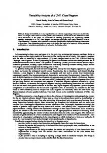
Rational Rose (RR) is solution software for visual modeling is used to construct, analyze, design, view, modify and manipulate one component. It can visualize the system behavior on the whole graphically through diagrams that are provided in this tool. RR is one of the most popular software used in designing software through UML (Unified Modeling Language) approach. Rational Rose tool has been widely used to analyze problem domain and to represent the system requirement graphically via appropriate diagram. [2]. UML class diagram describes the structure of the classes that form the system’s architecture. It is used to show the existence of classes and their relationships in the logical view of a system. This class diagram will be saved in a text form as .mdl file and known as petal file. This text structure represents the UML class diagram notations. This file can be accessed or opened by Rational Rose tool where the class diagram will be displayed graphically. Besides that, this file can also save the model in text form which can be read via notepad or WordPad. Structure of RR petal file that produced by Rational Rose (ended with .mdl atau .ptl), looks like LISP data structure which contains a few nested levels and ended with bracket, where it is shaped in tree node. This whole file is divided into two parts as being suggested by M.Dahm [3]. It is visualized in figure 1. Structure in this RR petal file is given attention because notation extraction process for object orientation model from UML class diagram will be conducted based on this input file.
Notation extraction process for a UML Class Diagram is involved two inputs from user. There are the input .mdl file from student as a solution for the coursework given and the input .mdl file from instructors as a solution model for that coursework. These files will be traced line by line to be match each notation keyword defined. Output is generated from this process will keep notation details in different tables. Figure 2 show the process flow for extraction process of notation of the UML class diagram.
(object Petal version _written charSet
45 "R ose 7.6.0109.2314" 0) [seksyen pertama:: ] First section
(object Desig n "Logical V iew" is_unit TR UE is_loaded TR UE : : root_usecase_package (object C lass_C ategory "Use C ase View" quid "4385E4570257" exp ortC ontrol "Public" global T R UE logical_m odels (list unit_reference_ list) logical_presentations (list unit_reference_ list : : root_category (ob ject C lass_C ategory "L ogical View " quid "4385E4570256" exp ortC ontrol "Public" global T R UE subsystem "C omp onent View" quidu "4385E4570258" logical_m odels (list unit_reference_ list (object C lass "Account" : : root_subsystem (ob ject SubSystem "C omp onent View " quid "4385E4570258" : : process_structure (ob ject Processes quid "4385E4570259" ProcsND evs (list : : properties (ob ject Prop erties attributes (list Attribute_S et (object Attribute tool "C plusplus" : : : [ Second seksyen kedua : ] section :
Fig1: Petal file of UML diagram
student
Input RR petal file
Instructor
Extraction Process
Data Tables
Assessment Process
Fig 2: Process flow for notations extraction
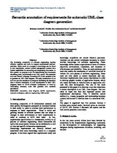
Class diagram is used to describe the structure of the classes that form the system’s architecture. It is used to show the existence of classes and their relationships in the logical view of a system. Figure 3 shows an example of a Account acNo : Int balance : Int = 0
account
customer
*
withdraw() deposit()
*
Customer name : String address : String
Transaction date : Date time : Time CheckingAccount credit_limit : Int
checkaccount 0..1
bank
1..20 CheckBook
check 1
Check
20..50
class diagram graphically for transaction process of a Banking System which was drawn using Rational Rose.
Fig 3: Example of UML Class Diagram for a Banking System
IJCSNS International Journal of Computer Science and Network Security, VOL.7 No.8, August 2007
183
transaction process of the Banking System given, it has six class objects as shown in table 1 below.
3.1 Class object notation In UML class diagram, classes and objects are represented as boxes with three compartments: the first compartment portrays the name of the class, the second depicts its attributes, the third its operations. Classes are abstractions that specify the common structure and behavior of a set of objects. Objects are instances of classes that are created, modified and destroyed during the execution of the system. An object has state that includes the values of its attribute and its links with other objects [4]. In class object notation, it is divided into three parts, and they are class name, attribute and operation. The class object, ‘Account’, below is one of an example of class object in the banking system and is shown in figure 4.
Table 1: data table SClass
IdClass
Class Account Customer Transaction checkingAccount Checkbook Check
K1 K2 K3 K4 K5 K6
Attributes can describe the properties of individual objects. The correct attributes capture the information that describes a specific instance of the class. An attribute has a type, which depict what kind of attribute it is. Extraction for attribute name of each class name could be recognized by its keyword,‘objects ClassAttribute’, as shown in figure x above. Result from this extraction process will generate data table named ‘SAtribute’ is illustrated in table 2.
Fig 4: An example of class object notation Table 2: data table SAtribute
The number of class object and its item depend on system requirement. The above class object notation is represented as text form in petal file Rational Rose is shown in figure 5. logical_models (list unit_reference_list (object Class "Account" quid "4385E498015E" operations (list Operations (object Operation "withdraw" quid "4385E844037D" : : :) (object Operation "deposit" quid "4385E85D030A" : : :) class_attributes (list class_attribute_list (object ClassAttribute "acNo" quid "4385E82C029C" type "Int") (object ClassAttribute "balance" quid "4385E8350096" type "Int" initv "0" exportControl "Public")))
IdClass K1 K1 K2 K2 K3 K3 K4
Keyword forKelas class Notasi Nama name : : Katakunci object objectClass Class
Keyword for Notasi operasi operation : Katakunci : object Operation object Operation
Keyword for
Notasi atribut Attribute: Katakunci : object ClassAttribute object Attribute
Attribute acNo Balance Name Address Date Time Creditlimit
Type_Attribute Int Int String String Date Time Int
Operations are used to manipulate the attributes and are normally called functions. It can be applied only to objects of that class. The operation in a class is described what the class can do. Extraction for operation’s name for each class could be recognized by its keyword, ‘objects Operation’, as shown in the above figure. Result from this extraction process will generate data table namely ‘SOperation’. Table 3 shows data that is generated from this extraction process. Table 3: data table Speration
FigRajah 5: Extraction classbagi object xx : Ekstrakfor notasi kelasnotation
The name of the class should be derived from the problem domain. It should be a noun; for instance, Account, Customer, Check and so on. Extraction for the name of each notation could be recognized by its keyword, ‘object class’, as shown in the above figure. Result from this extraction process will generate data table named ‘SClass’. This table will keep all the names of object class notation that involved in class diagram. Referring to the class diagram for
Class_Name K1 K1
3.2
IdOp Op1 Op2
Operation Withdraw Deposit
Relationship Notations
Class diagram consists of classes and the relationship between classes. We define four basic relationship based on
IJCSNS International Journal of Computer Science and Network Security, VOL.7 No.8, August 2007
184
its function. The relationships that can be used are Association, Association Class, Aggregation, generalization and composition. •
Generalization Notation
A class hierarchy is a graph where classes are connected to each other via generalization relationship. Generalization (sometimes called inheritance) is a relationship between a general and a specific class. Generalization is shown as a solid line from the more specific class (the subclass) to the more general class (the superclass), with a large hollow triangle at the superclass end of the line [4]. An example of a generalization relationship in class diagram for a banking system is shown in figure 6.
Account acNo : Int balance : Int = 0 withdraw() deposit()
CheckingAccount credit_limit : Int
class name of each generalization relationship is recognized by its keyword, ‘superclasses’, as shown in the above figure. Result from this extraction process will generate data table named ‘SInherit’. Table 4 shows data generated from this extraction process. Table 4: data table SInherit
Id 1
•
Subclass CheckingAccount
Superclass Account
Association and Association Class Notation
Association - Association relationship shows the communication between two or more classes. It can be drawn by solid line between classes. Association often has a name that near the line representing the association, and also consist of the cardinality that expresses how many objects are linked. An example of this relationship is illustrated in figure 8. Association class - Association class allows association to be attached to a new class. It is used to add information on a link and can be drawn by a dotted line across the association line [4]. An example of this relationship also is illustrated in figure 8.
Fig 6: An example of generalization notation Account acNo : Int balance : Int = 0
Figure 7 shows the text form produced in Rational Rose petal file that represent the generalization notation in figure 6.
account *
withdraw() deposit()
*
Customer name : String address : String
Transaction date : Date time : Time CheckingAccount Fig credit_limit : Int
Keyword for Mewakili Kelas1 Subclass: (yang mewarisi) object Class
customer
8: Association and Association Class notation
Figure shows the text form produced in Rational Rose checkaccount9 0..1 petal file that represent this notation. bank
Keyword for Notasi pewarisan Generalization: Katakunci : superclasses superClassess
(object Class "Checking Account" quid "4451A58402E7" superclasses (list inheritance_relationship_list (object Inheritance_Relationship quid "4451A5AC024E" supplier "Logical View::Account" "4385E498015E"))) quidu
Keyword for Mewakili Superclass : Kelas2 (yang diwarisi) Supplier
Fig 7: Extraction for generalization notation
Generalization or inheritance enables us to describe all the attributes and operations that are common to a set of classes. The specific class, called the subclass, inherits everything from the general class, called the superclass. Extraction for
1..20 CheckBook
Keyword for Association: Object Association
Keyword for Association’s name: object Role
check
Check
20..50 1 (object Association "$UNNAMED$0" quid "4385E4F801E9" roles (list role_list (object Role "customer" quid "4385E4F9032A" label "customer" supplier "Logical View::Customer" quidu "4385E4B80381" client_cardinality (value cardinality "*") exportControl "Implementation" is_navigable TRUE) (object Role "account" quid "4385E4F9032C" label "account" supplier "Logical View::Account" quidu "4385E498015E" client_cardinality (value cardinality "*") exportControl "Implementation" is_navigable TRUE)) AssociationClass "Logical View::Transaction")
Fig 9: Extraction for association notation
Keyword for class: Supplier
Keyword for cardinality: Value cardinality
Keyword for Association status: is_navigable
IJCSNS International Journal of Computer Science and Network Security, VOL.7 No.8, August 2007
An association for each class depict as a role name in petal file as a text form as shown in the above figure. Role names are part of the association and it is optional. Extraction for each item in association relationship is recognized by specific keyword that is shown in the above figure. Result from this extraction process will generate data table named ‘SRelation’. Table 5 shows data generated from this extraction process based on the class diagram for the banking system given before.
Aggregation and composition relationship is determined by text Containment in Rational Rose petal file. They are distinguished by the value of keywords in the figure 13 below. Containment // aggregation or composition ? is_navigable // association is_aggregate // aggregation?
Table 5: data table SRelation
IdH Class1 H1 Customer H2 Transaction
Kd1 Class2 * Account
Fig 13: text structure for aggregation and composition notaiton
Kd2 THub * Association Association Class
• Aggregation and Composition Notation Aggregation - An aggregation denoting a whole-part relationship between two classes. An object composed of one or more other objects, each of which is considered a part of the aggregate object. Class diagram of the Banking System does not have this relationship. However, to show this notation clearly, we illustrate generally in figure 10 that shows an aggregate as a line with a hollow diamond attached to one end of the line. ClassName
185
ClassName
Table 6 is used to determine the types of relationship. Table 6: Types of Relationship
Type Aggregation Composition
Containment “By Value” “By Reference”
is_navigable TRUE TRUE
is_aggregate TRUE TRUE
A Composition also held in roles structure in Rational Rose petal file. Extraction for each item that indicates a composition association relationship can be recognized by specific keyword as shown in the above figure. The result from this extraction process will then be kept in table ‘SRelation’. Table 7 shows the data expanded from this extraction process based on class diagram for the banking system given before.
Fig 10: Aggregation notation Table 7: data table SRelation
Composition - A Composition aggregation owns its parts with strong ownership. It can be shown with a line and a solid diamond attached to the whole side. Example of composition is shown in figure 11.
Id H1 H2 H3
Classs1 Kd1 Class2 Customer * Account Transactio n Check 20.. Checkbook 50
Kd2 THub * Association Association Class 1 Composition
Fig 11: composition aggregation notation
Figure 12 shows the text form produced in Rational Rose petal file that represent the composition aggregation notation in figure 11. roles
(list role_list (object Role "check" quid "4385E61B002E" label "check" supplier "Logical View::Check" quidu "4385E4E302C5" client_cardinality (value cardinality "20..50") Containment "By Value" exportControl "Implementation") (object Role "$UNNAMED$5" quid "4385E61B0038" supplier "Logical View::CheckBook" quidu "4385E4D803C3" client_cardinality (value cardinality "1") exportControl "Implementation" is_aggregate TRUE)))
All of these tables will be used to implement assessment process to determine either student’s diagram input is correct or not. It is also used to specify either it is matched with teacher’s diagram as a solution model of UML class diagram or not.
Keyword for Mewakili object aggregated Kelas1
4. Analysis and comparison
Keyword for Composition Mewakili Containment "By Value"
The main objective of our research is to evaluate UML class diagram that is produced by students. The class diagram must be drawn using Rational Rose tool. Rational Rose stores the diagram in a file which is called petal files. The input for this system is petal file Rational Rose with extension .mdl. The process is to assess or evaluate the input given by students whether it is errors free or not.
Supplier
hubungan is_aggregate TRUE composition
Fig 12: Extraction for composition aggregation notation
186
IJCSNS International Journal of Computer Science and Network Security, VOL.7 No.8, August 2007
The output of the system is a list of comments on the students’ diagram, in a text format, as guidance to the students. This guidance will be used by students to modify their UML class diagrams if these diagrams contain any errors. This feedback also will be used by students to evaluate their level of understanding in designing the system requirement using UML class diagram. By reviewing their old answers and the feedback given by this system, the students can correct their submission and learn from their mistakes. This system also can omit the differences in evaluation between different instructors who check the same exercise. Beside that, students can submit their answer for multiple assessments and receive immediate feedback on the answers. However, this system does not produce any grades or marks. The purpose of CASE tools is to reduce the gap between theory and practical. However, the tools do not focus on the learning environments which need more aids to increase users’ understanding especially for students. The first attempt at using computers to automate the process of assessing student work was reported in the early 1960’s [5]. Early automatic assessment systems were built almost exclusively towards computer science related subjects, especially programming and numerical based subjects. A lot of research has been done on assessing subjects that is in the form of text based. Previous researches focus more to programming exercise assessment. Over the years, there have been dozens of different systems created where its early start was in 1961 by Forsythe and Wirth [6]. Examples of this type of assessment systems are created by Naur [7] that grade the Algol programming, ASSYST [8] that automate the assessment system for ADA program, Ceilidh [9], which is an assessment system for C, C++ and UNIX programming, and Style++ [10] that was used to measure programming styles for C++ program. Research that refers exclusively to the automation of assessment of student diagrams however has not yet received much attention. Research by Thomas et al [11] used the notion of patterns to successfully apply to the automated marking of student attempts to drawing entity-relationship (ER) diagrams. TRAKLA2 [5] is an automatic assessment systems for data structure and algorithm exercises at Helsinki University of Technology. CourseMaster and DATsys system [12] are two platforms built at the University of Nottingham to support diagram-based exercises. Diagram notation specifications are authored by the course developer using its own authoring tool and use its own platform for assessing UML Class diagrams, flowcharts and logical circuits automatically. Some students experiencing difficulties were helped by CourseMaster’s feedback and as a result were able to draw the correct diagram. System will then give a list of correct
notations in diagram as a feedback to students. Student’s experience stated by marking status produced by the system such as ‘excellent’, ‘correct’ and ‘rotten’. In the previous system, they use their own platform to get the input of the diagram and to be assessing directly. Our proposed automatic assessment system can get the input from existing authoring tools to draw UML diagram, Rational Rose, and the assessment process is divided into three modules namely the class structure analysis module, verification process and language checking module. Each module process is inter-related with each others. This means that each module will be implemented in sequence. This sequence process is vital in order to make sure the input of the students’ UML class diagram match with those of instructors. For example, the second process is the verification process; it cannot be activated if errors have been detected in the first process. Assessment processes are carried out in order to verify that the input diagram is error free. Apart from that, it will also generate list of feedback to be used as guidance to the students and hopefully it helps to improve their understanding in subject matter. The automatic assessment process was done by the system is accomplished by comparing the students’ diagram with the solution diagram. Prior to implementing the comparison process, we use notation extraction technique to derived each notation in the UML class diagram and keep it as data in appropriate tables.
5. Conclusion As a conclusion, extraction process is the method to convert the notation information into data that could be extracted from text structure in Rational Rose petal file involved in the diagram assessment process. This extraction process is needed to implement the assessment process for UML class diagram. Our research focuses more on UML class diagram since it describes the existence of classes and their relationships in the logical view of a system. We can draw this diagram using Rational Rose that is a computer aided software engineering (CASE) tool used for object-oriented software development with Unified Modeling Language. UML Class Diagram can be drawn using this CASE tool and can be saved as a file with .mdl extension. This .mdl file is also known as petal file that is displayed as a text structure. The text structure is represented differently based on the UML class diagram drawn by users.
References [1] S. Bennett, S. McRobb and R. Farmer, Object-oriented systems analysis and design using UML . Glasgow:McGraw-Hill. 2002.
IJCSNS International Journal of Computer Science and Network Security, VOL.7 No.8, August 2007
[2] Fundamentals of Rational Rose, student manual, version 2002, Rational software corporation, Rational university, US. 2002. [3] M.Dahm, Grammar and API for Rational Rose Petal files, 2001. [4] E. Hans-Erik and M.Penker, UML Toolkit, John-Wiley & Sons. 1998 [5] J. Nikander, Managing Automatically Assessed Exercises in TRAKLA2, Master Thesis, 2005. [6] G.,Forsythe and N.,Wirth Automatic grading of programs, Communication of the ACM, Issue 8, 275278.1965. [7] P.Naur. Automatic grading of students’ ALGOL programming. BIT 4, pages 177–188, 1964. [8] D. Jackson and M. Usher. Grading student programs using ASSYST. In Proceedings of 28th ACM SIGCSE Tech. Symposium on Computer Science Education, pages 335–339, San Jose, California, USA, 1997. ACM Press, New York. [9] S.D.Benford, E.K.Burke, and E.Foxley. Courseware to support the teaching of programming. In Proceedings of the Conference on Developments in the Teaching of Computer Science, pp.158–166.University of Kent, 1992. [10] K.Ala-Mutka, T. Uimonen, and H-M. Järvinen. Supporting students in C++ programming courses with automatic program style assessment. Journal of Information Technology Education, 3:245–262, 2004. [11] P.Thomas. N.Smith and K.Waugh, Computer Assissted Assessment of Diagrams, Proceedings of the ITiCSE ’07, 68-72, 2007. [12] C. Higgins, P. Symeonidis, and A.Tsintsifas. The marking system for CourseMaster. In Proceedings of the 7th annual conference on Innovation and Technology in Computer Science Education, pages 46–50. ACM Press, 2002.
Noraida Haji Ali received the B.Sc. and M.Sc. degrees in Computer Science from Universiti Kebangsaan Malaysia in 1995 and 1999, respectively. After working as a tutor (from 1997-1999), she has been a lecturer at Universiti Malaysia Terengganu until present. Her teaching interests are in the areas of Computer Programming, Graphic Programming and Object-Oriented Analysis and Design. Now she furthers her study in PhD at Universiti Kebangsaan Malaysia in software engineering area. She was doing her PhD research in object-oriented and formal modeling in specific area.
187
Zarina Shukur is a faculty member in the Computer Science Department of the Faculty of Information Science and Technology at Universiti Kebangsaan Malaysia. She holds a PhD in Computer Science from the University of Nottingham, UK. She has been faculty member in UKM since 1996. Her research interests are in the areas of Teaching of Programming and Formal Methods.
Sufian Idris is a faculty member in the Computer Science Department of the Faculty of Information Science and Technology at Universiti Kebangsaan Malaysia. He holds an MSc in Computer Science from The University of Manchester, UK and a PhD in Computer Science from the University of Manchester Institute of Science and Technology, UK. He has been faculty member in UKM since 1988. His teaching interests are in the areas of Computer Programming, and Object-Oriented Analysis and Design. His research interests and work are in the areas of Teaching of Programming, Programming Tools, Object-Oriented Development and Mobile Computing. He has published papers in journals such as the WSEAS Transactions on Computers and conferences such as the International Conference on Enterprise Information Systems.