Chapter 4. Foundations. Introduction 4.1. Foundation types 4.2. Foundations on
an incline 4.3. How to calculate loadings 4.4. Using spreadsheets to calculate ...
Chapter 4
Foundations Introduction 4.1 Foundation types 4.2 Foundations on an incline 4.3 How to calculate loadings 4.4 Using spreadsheets to calculate loadings 4.5 Foundation design theory 4.6 Ground surveys 4.7 Desk top surveys 4.8 Foundation materials 4.9 Health and safety issues relating to concrete and cement 4.10 Problems with foundations 4.11 Soils and substrata 4.12 Safe loads in subsoils 4.13
Building in the 21st Century
4.1 Introduction This and the next three chapters introduce the fundamentals of construction. They have been divided using an elemental approach, starting in this chapter with the foundations. Perhaps the most vulnerable part of a building and certainly the most costly to repair, foundations are not infrequently incorrectly designed or constructed. In the construction industry there is no regulation or requirement for a builder to have any qualifications whatsoever. The designer must comply with regulations, and reputable companies have been trying to ensure they have qualified and experienced staff to undertake the work. Why, then, are there so many claims on insurance for foundation failure? This chapter starts by defining the functions of foundations and some of the issues relating to the effects of water, the most common challenge to the builder. The various designs of foundation are discussed in relation to soil types and types of loading. The introduction to the use of spreadsheets will enable the reader to carry out simple calculations quickly and efficiently. The more complex calculations would normally be carried out by a qualified structural engineer using professional computer software.
Foundation function The purpose of a foundation is to transfer the imposed load of a building or structure onto a suitable substratum.
Considerations Loadings There are three main types of load: 1 Dead loads are the static or constant weight of the structure made up from the walls, floors, roof, etc. 2 Live loads (also known as imposed loads) such as furniture, goods and people, are movable. In addition there are variable loads caused by the weather, such as snow and rain. 3 Wind loads can be positive or negative. They are not dead or imposed and therefore require specific consideration. Loads can be calculated and expressed as a force (weight) that is to be transferred onto the substrata.
Substrata bearing capacity The bearing capacity of the substrata is the amount of weight the ground (substrata) can support. For a structure to be stable, the force (load) bearing down must be opposed by an equal force pushing upwards. When both upward and downward forces
146
Building in the 21st Century
Heave
4 Foundations
Forces pushing down
A
B Subside Forces pushing up
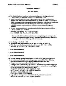
Forces pushing down must equal the forces pushing up. If one force is greater than the other then that force will continue to move in that direction. For example: If force A is greater than force B the building will sink – SUBSIDENCE If force B is greater than force A the building will be pushed upwards – HEAVE
Figure 4.1 Ground movement and forces.
are of the same magnitude (size) they are said to be in equilibrium. When the downward force is greater than the upward force, the structure will sink or subside. Conversely, a larger upward force than downward force can push the structure upward, causing it to heave (Figure 4.1).
What causes heave? The main cause of movement of buildings is the weather; those on clay soils are most affected. If clay dries out during a period of drought it will shrink, causing uneven support beneath a structure. Figure 4.2 shows how ground around a building has dried out from the effects of the Sun and access to air, whereas the ground beneath the building remains moist; the resulting uneven support for the building may cause the foundations to fail. In the past three decades there have been several severe droughts causing hundred of millions of pounds worth of damage each year. With climate change and a predicted increase in frequency of periods of low rainfall the problem will continue. Building Regulations Approved Document A: 2004, para: 2E4 requires foundations in clay to be a minimum depth of 0.75 m below ground level because it is
4 Foundations
147
Building in the 21st Century Figure 4.2 Subsidence caused by water evaporation.
considered that the effects of the Sun cannot penetrate down to that level. However, it is the building control inspectors who will decide the required depth on site; this is commonly at least 1.00 m. If tree roots or soft spots are found, the required depth of foundations can increase significantly. In other non-cohesive soils, such as sands and gravels, the minimum depth of foundations can be 0.45 m. What else can affect the bearing capacity of the ground? Water can have significant effect on the ground; some clay soils can increase in height (swell) by up to 75 mm between dry and saturated. As the moisture levels rise, the plasticity of clay increases allowing landslip (see Chapter 3, Figure 3.56 which shows large areas of cliff that have subsided as a result of heavy rain saturating the lower stratum, making it more plastic and allowing upper layers of more dense clay to slide down the cliff). Another cause of water loss is the presence of trees, in particular broad leaved trees such as apple, oak, beech and poplar, which remove vast quantities of water from the ground in the spring and summer months during their growing period. Water and nutrients are extracted from the ground by the roots and transported through the plant to the leaves from which large volumes of water evaporate; this is known as the transpiration stream. Trees absorb carbon dioxide which combines with water in the leaves to produce sugars for plant growth, releasing oxygen as a waste product; this process is called photosynthesis. In drought conditions trees continue to evaporate water brought in via their root system. During continual drought the trees will drop many of their
148
Building in the 21st Century
4 Foundations Figure 4.3 Differential ground movement.
leaves to conserve water in the trunk; however, the ground around the tree will have been seriously depleted of water (becoming desiccated). The microscopic particles that make up clay are known as platelets. They are like sheets of glass 0.002 mm in diameter and impervious to water. (If they were placed end to end there would be 128 000 across the diameter of a 2p coin.) When the platelets are completely dry they occupy a minimum volume and the clay becomes very hard, shrinks and cracks, as shown in Chapter 3, Figure 3.49. When wetted the clay swells causing heave and softens (becomes plastic). When clay is saturated, its compressive strength is reduced considerably (by up to 50%) because the platelets become lubricated and easily move over each other. For example, after heavy rain site vehicles may not be able to operate because they would sink into the softened clay. Clay substratum can lose up to 50% of its load bearing capacity and buildings may subside (subsidence). In Figure 4.3, structure A may be pushed evenly upward and therefore is unlikely to be damaged. However, if the ground strata change as beneath structure B, the upward force will be uneven and may result in reduced load bearing capacity causing slip and heave, so structural damage is likely. Frost can also cause heave in saturated clay, although generally only about the top 0.6 m will be subject to movement. Horizontal pressure can cause sub-ground level walling to be moved if inadequate backfill or cavity fill has been used. Figure 4.4 shows the potential problem and Figure 4.5 the consequence. Other causes of ground movement can include broken drains and changes to water courses (see also Chapter 3). Water abstraction for irrigation, manufacture or human use can have considerable effects on ground stability. Where the land is adjacent to tidal rivers or sea, the ground may swell and shrink with the tidal cycles. This is particularly common in marsh of fibrous peaty substrates. Old mines which have not been charted, and therefore remain undiscovered in modern times, can be a major cause of subsidence; for example, mines for coal, iron ore, copper, tin, zinc and galena, stone extraction for building in and
4 Foundations
149
Building in the 21st Century Figure 4.4 Lateral forces caused by freezing water.
around Bath and parts of Derbyshire, or flints in parts of Norfolk (see also Section 4.12).
4.2 Foundation types Not all buildings need foundations. For example, in areas where the bedrock is close to the surface it is possible to level it off and build directly onto it. Why try cutting a trench into rocks like granite and dense limestone, then to fill it up with concrete mainly composed of granite or limestone? Soils, however, are not as strong as rock so therefore foundations will be required.
Spread footings These were commonly used on structures prior to about the 1920s. The principle was to broaden the base of the wall using brickwork as inverted corbelling. Beneath the first course, sand, ash or coal dust would be used to provide a smooth surface to the formation level (Figure 4.6).
150
Building in the 21st Century
4 Foundations Figure 4.5 Potential failure caused by lateral forces.
G.L.
Figure 4.6 Spread footings.
Strip foundations Traditional strip Foundations are a continuous concrete section supporting load bearing walls. If they are in plain concrete they must be at least 150 mm thick to prevent shear
4 Foundations
151
Building in the 21st Century
A
A
A common problem if the concrete is too thin, too weak or attacked by sulfates
Figure 4.7 Shear failure in a strip foundation.
Figure 4.8 Shear failure in a strip foundation due to various causes.
P
t
For example: Width of foundation strip 600 mm − 257 mm
Width of wall 2 x projection (P) ... P
=
343 2
343 mm P = 172 mm
Figure 4.9 Rules for a simple strip foundation design.
failure at point A in Figures 4.7 and 4.8. To calculate the thickness (t) of the strip the overall width must be known (see foundation calculations in Sections 4.5 and 4.6). If, say, the width has been calculated as 600 mm, subtract the width of the wall and divide by two. The result will be the projection (P) and must be the same or less than t for unreinforced strip foundations (Figure 4.9).
152
Building in the 21st Century
4 Foundations
Figure 4.10 shows the downward loading spreading at about 45◦ ; therefore if the thickness P of the strip is less than the projection, the concrete may shear. If t is equal to P the force will be spread over the whole underside of the founda45° tion strip (Figure 4.11). Another cause of shear in strip foundations is sulfate attack. Aggressive soils may contain sulfates, either in crystal form which look like granulated sugar or in a soluble state in the Figure 4.10 Problems if the rules are not followed. groundwater (Figure 4.12). The sulfates dissolve the cement binder and the foundations become weak and fail. One common remedy is underpinning.
Deep strip Because drought conditions now occur more frequently, the depth of the strip has increased over the past three decades, especially in clay soils where a required minimum depth of 1.00 m below ground level is now common. Within the loading area there should be no made ground, nor wide variation in the type or structure of the substrata, as this will produce irregular loading. The digging of clay for local brickworks in Victorian times would leave large excavations which were subsequently filled with anything to be disposed of: factory waste, rubbish, and used night soil (night soil was dried and ground clay used by Victorians to place over their effluent before flushing water toilets became fashionable; at night men would empty the full buckets of clay and effluent and leave another bucket full of dry ground clay for the next day). Likewise, the excavations left after digging out building sand or clay for night soil, would be filled to give made ground. Other made ground could include in-filled Victorian cess pits, in-filled ponds and rivers, or ground where structures have previously been, especially those with basements or coal holes.
G.L.
The load spreads at about 45° through the foundation
Figure 4.11 Loading forces.
4 Foundations
153
Building in the 21st Century Sulfate crystals
Figure 4.12 Sulfate crystals in clay.
Deep strip foundations were introduced as building land became more scarce and access to deeper load bearing strata was required. The trenches must be wide enough for the ground worker and the bricklayer to gain access. This means the amount of spoil to be removed is greater than the need for the foundation (Figure 4.13). In loose (friable or granular) soils, such as gravel and/or sand, peat and clay, the walls of the trench need to be supported by boarding. The struts have to be worked around which makes slow going and can lead to dangerous practice (Figure 4.14). Deep trenches in cohesive soils should also be treated with respect. They can change in cohesion by drying out and cracking, or becoming plastic and sliding in. Working in an open trench without support, even at waist height, can be fatal. The weight of soil can be about 1 tonne/m3 , more than enough to crush internal organs. Ground workers often throw buckets of water into open trenches in hot weather to prevent them drying out; covering the trenches with boarding and polythene can also help. Signage and barriers should be placed warning of the excavation. A typical detail showing the relationship between a solid floor and a deep strip foundation is shown in Figure 4.15.
Trench fill In the early 1970s the house building boom meant that labour was in high demand and consequently expensive. Machine dug trenches that could
154
Building in the 21st Century
4 Foundations
G.L.
Figure 4.13 Deep strip foundation.
Figure 4.14 Deep strip foundation with trench support.
be filled with mass concrete became popular. It reduced the amount of spoil that had to be dug as no bricklayers needed access in the trench (Figure 4.16). In most cases trench support is not required; the amount of backfill required and spoil to be removed is reduced. The savings offset the extra cost of the concrete. If the loading requires, say, a 450 mm
4 Foundations
155
Building in the 21st Century Figure 4.15 Solid ground floor with deep strip foundation.
Figure 4.16 Trench fill foundation.
wide trench 1.5 m deep, a backactor could excavate to those dimensions. In contrast, a traditional strip would require the extra working space (see Figure 4.13). A typical detail showing the relationship between a solid floor and a trench fill foundation is shown in Figure 4.17.
156
Building in the 21st Century
Sand / cement screed Concrete oversite Floor grade rigid insulation Damp proof membrane
4 Foundations
Damp proof course
Sand blinding
1200 mm
Consolidated hardcore 255 mm Thermalite trenchblock laid in 1:4 cement / sand mortar Trench fill foundation C10P
Figure 4.17 Solid ground floor with trench fill foundation.
Wide strip Where the soil is soft or of a low load bearing capacity, wide strip foundations can be used to spread the load over a larger surface area so that the loading per m2 is reduced. (This is similar to standing on the bed: as shown in Figure 4.18, your weight will easily compress the mattress. If, however, you place a strong board (say 600 mm2 ) on the bed first, although there is additional weight (you plus the board) the load bearing area has increased significantly, so decreasing the loading per m2 ). It can be seen in Figure 4.19 that it will be very expensive in terms of concrete to achieve the required ratio of P to t, so steel reinforcement is used. However, the density of concrete must be increased to prevent water penetration.
Figure 4.18 Load over area comparisons.
4 Foundations
157
Building in the 21st Century Figure 4.19 Wide strip foundation.
Simple raft Where the subsoil is very weak the load needs to be spread over a greater area. This is achieved by casting a slab of concrete over the whole ground area and thickening the slab where walls are to be placed (Figures 4.20 and 4.21). If ground pressures are likely to be excessive at different seasons, reinforcement may be required; this is known as fabric when in sheet mesh form.
Figure 4.20 Simple raft foundation.
158
Building in the 21st Century
4 Foundations Figure 4.21 Reinforced raft foundation.
Pad Pad foundations are used when isolated loads need to be supported, such as columns or framed structures. The load would be concentrated in relatively small areas of the pad with large expanses being either non-load bearing or having lightweight loadings, meaning that small slabs to spread the load from the skeletal structure can be cast. Figure 4.22 shows a simple pad below a steel stanchion. Steel reinforcement may be required for higher loadings. The type of skeletal frame will determine the pad foundation design. For example, a cast in-situ concrete column will require a kicker and continuity bars to be cast into the pad (Figure 4.23). Steel frame, timber frame or precast concrete framed structures will require holding down bolts to be cast into the top of the pad or sockets to be formed (see Chapter 8).
G.L.
Figure 4.22 Simple pad foundation – steel frame.
4 Foundations
159
Building in the 21st Century
Concrete column G.L.
Continuity bars
Kicker
Figure 4.23 Simple pad foundation – RC frame.
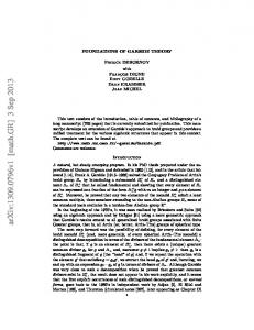
Short bore pile and beam Where the ground conditions will not support strip foundations it may be possible to create a series of concrete columns (piles) that can reach down to stronger strata. Short bore piles are typically 2.00–3.00 m long. They can be reinforced with steel if there are any lateral forces present, or just concrete if all forces are vertical. At the top (cap) of each pile a connection must be made with a horizontal reinforced concrete section termed the beam (Figure 4.24). A typical detail showing the relationship between a block and beam floor and a short bore pile and beam foundation is shown in Figure 4.25; Figures 4.26 and 4.27 show the relationship between the piles and beam and the structure. The advantages of pile and beam foundations are as follows:
r in clay soils, if correctly designed, they are not affected by clay heave or shrinkage
r groundwater can percolate between piles easily r limited tree roots have little effect as piles conr r Figure 4.24 Short bored pile and beam.
r r
160
tinue further below the surface than any tree root system techniques available to overcome groundwater whilst piling, so dewatering not required reduced quantity of spoil and minimal ground disturbance less concrete required than with the same depth of strip foundation precast concrete beams can be used, eliminating casting time on site.
Building in the 21st Century
4 Foundations Figure 4.25 Suspended block and beam floor on a short bored pile and beam foundation.
Figure 4.26 Isometric view of a pile and beam foundation.
The main disadvantage of pile and beam foundations is cost. The technique requires specialist plant and labour; however, the extra expense can be offset against the rising cost of spoil removal and time savings. Figure 4.28 shows a piling rig. A long metal screw termed an auger is turned into the ground like a corkscrew. The soil is removed when the auger is brought to the surface. A wire brush located next to the auger cleans off the spoil stuck to the blade (Figure 4.29). Figure 4.30 shows the pile reinforcement cage before it is lowered into the pile shaft, and Figure 4.31 shows a pile cast with the reinforcement protruding ready for the pile cap and beam to be attached.
4 Foundations
161
Building in the 21st Century Figure 4.27 Isometric view of a pile and beam foundation supporting a building.
Figure 4.28 Crawling piling rig and auger.
4.3 Foundations on an incline When building on a hill it may not be practical to level off the ground so stepped foundations would be used. Other than pad foundations, all the previously described designs can be detailed with steps. Figure 4.32 shows a strip or
162
Building in the 21st Century
4 Foundations Figure 4.29 Piling auger and cleaning brush.
Figure 4.30 Pile cages.
4 Foundations
163
Building in the 21st Century Figure 4.31 Pile cage ready to receive pile cap.
h must not be greater than t
h
o
t
o must be at least 2 x h but not less than 300 mm
Figure 4.32 Stepped strip foundation.
raft foundation step. The Building Regulations requirement is that the overlap must be at least two times greater than the thickness of the foundation and not less than 300 mm. The thickness of the foundation should be designed to course in with the masonry walling. For example, if cavity walling is to be used, the step could be equal to three brick courses or one block course. The overlap will be 2 × 225 mm = 450 mm. Where pile and beam foundations are to be used, the step should be directly over a pile; however, the exact design will be decided by the structural engineer for the specific application (Figure 4.33).
164
Building in the 21st Century
4 Foundations Figure 4.33 Stepped pile and beam foundation.
4.4 How to calculate loadings Look at the plans for the proposed structure and consider the location of the heaviest section. Figure 4.34 shows a section through a two storey dwelling of traditional construction with a gable roof; Figure 4.35 shows the directions of the imposed loading forces in red arrows and the resistant force in yellow arrows. Start at the roof and work down:
r Look at which way the roof is spanning. Does it rest on just two walls or is there another load bearing partition wall taking some of the load? In the example the first floor partition is non-load bearing; therefore the roof spans the external walls. r Then consider which way the floors are spanning. If the drawings show floor joists they are in the direction of the span (Figure 4.36). However, some structures have precast concrete, cast in-situ concrete, or even steel decking. In those cases the symbol will be shown on the plans. r Is the ground floor a suspended floor or a solid floor? A suspended floor will transfer imposed loadings onto the supporting walls, whereas a solid floor will be supported on the ground without transferring any load to the walls. r Is the first floor supported by a load bearing partition wall? In the example a load bearing partition 100 mm thick is supporting the suspended first floor. Some floors are designed to span between cross walls only (see Chapter 8, Section 8.2).
4 Foundations
165
Building in the 21st Century Figure 4.34 Cross section of a simple domestic structure.
r Look at the type of walls. Are they brick and block, or timber frame? It r
r r r
is usual for the inner leaf of a cavity wall to be the load bearing leaf, but this is not true of all walls. Are there any internal partition walls being supported by the floors? Partitions walls form rooms; therefore, although they may not be load bearing walls, they will be part of the dead loading. In the example there is a non-load bearing first floor partition wall. Are there any water storage cisterns or tanks in the loft area or upper floors? Water weighs 1 kg per litre; therefore a cold water tank can impose a considerable load. What is the considered type of foundation? What is the live loading? Live loadings on floors are predicted for specific usage such as domestic at 1.5 kN/m2 as stated in BS 6399: 1996. Table 4.1, reproduced from Approved Document A of the Building Regulations, provides a guide to the imposed loading for domestic applications with a slightly higher figure of 2.00 kN/m2 .
Now that the initial observations have been carried out, the location of the maximum loading on the subsoil can be calculated. Ignore any windows or doors, and consider only one lineal metre of the structure as shown in Figure 4.37.
166
Building in the 21st Century
4 Foundations Figure 4.35 Cross section showing direction of forces.
The symbol showing the direction of span
Figure 4.36 Simple joist layouts.
It is important to be familiar with the materials being used; however, the calculations will not be precise. Bricks, for instance, can vary in weight, as can different makes of concrete block; therefore recognised values are used. The calculations are generally carried out by a structural engineer on behalf of the designer.
4 Foundations
167
Building in the 21st Century
Table 4.1 Imposed loadsa . Element
Loading
Roof
Distributed loads: 1.00 kN/m2 for spans not exceeding 12 m 1.5 kN/m2 for spans not exceeding 6 m
Floors
Distributed load: 2.00 kN/m2
Ceilings
Distributed load: 0.25 kN/m2 Together with concentrated load 0.9 kN
a
Crown copyright: Building Regulations Approved Document A: 2004, Table 4.
Figure 4.37 Isometric section through a simple domestic structure.
A list of common weights for building materials can be found in BS 648:1964 Schedule of Weights of Building Materials, manufacturers’ technical catalogues (many of which can be downloaded from the manufacturers’ websites) and Table 1 of BS 6399-1:1996 which gives minimum imposed floor loads.
168
Building in the 21st Century
4 Foundations
hypotenuse
pitch adjacent adjacent hypotenuse hypotenuse =
hypotenuse =
adjacent
4.00 m cosine 30°
hypotenuse = 4.62 m Add say 400 mm for the eaves overhang
+ 0.40 m
Total length of sloping side = 5.02 m
Figure 4.38 Roof calculations.
Example It can be seen from Figure 4.34 that the span of the dwelling is 8.00 m. Half the load will bear on each wall; therefore only half the roof need be considered. To calculate the weight of the roof tiles, the length of the rafter must be found. Use of basic trigonometry to calculate the pitch or angle shows that it is 30◦ (Figure 4.38).
r What information is known? The angle and the adjacent length. r What information is required? The length of the hypotenuse. r Which formula should be used? cosine α = Adjacent Hypotenuse
Transpose the formula so that the unknown is on one side of the equals sign and the known is on the other: 4.00 m Hypotenuse 4.00 m Hypotenuse = cosine 30◦ Hypotenuse = 4.62 m cosine 30◦ =
4 Foundations
169
Building in the 21st Century
There is an overhang at the eaves; therefore add, say, 0.40 m to the length of the rafter making it 5.02 m × 1 m = 5.02 m2 . You may want to simplify the calculation process by preparing a spreadsheet and entering the materials methodically, working down from the roof (see Section 4.5).
Roof loading The roof trusses will be covered with sarking and then battens ready to take the tiles or slates. The tile manufacturers often supply an as laid weight per m2 where the tiles, sarking and battens have all been included; if this is not the case they will need to be added. To the bottom edge of the truss will be a layer of plasterboard (the ceiling) which in turn supports the loft insulation.
Wall loading The external wall height should now be measured. In the example in Figure 4.34 it is 5.20 m. Enter the data onto the spreadsheet.
Floor loading Look for the longest span of floor bearing onto the wall. Figure 4.34 shows 4.50 m; therefore half the floor load will bear on the external wall and the other half on the load bearing partition wall. Enter the data onto the spreadsheet. In the example a non-load bearing partition wall on the first floor is bearing down onto the suspended floor; therefore measure the height of the partition and divide by two. (It is assumed that the load will be taken equally onto each end of the floor bearing walls – if the wall is significantly nearer one end of the floor joist, or of substantial weight such as brickwork, then more complex calculations would be required.) Enter the data onto the spreadsheet. If the ground floor is suspended, a similar calculation will be required. In the example a solid floor has been shown so no weight will be transferred to the walls. In addition to the floor and partition which are termed dead loads as they do not move, there are imposed loads or live loads. Furniture and people are moveable; therefore a given loading from BS 6399 Part 1 has been used. Depending on the use of the building, the minimum loadings start at 2.00 kN/m2 for domestic dwellings. The floor area multiplied by the loading should be entered onto the spreadsheet.
Natural loadings Wind The only loading that has not been considered so far is wind loading. Wind is not a live load. It can exert positive pressure on one part of a
170
Building in the 21st Century
4 Foundations
structure and at the same time negative pressure (suction) on another part. Calculating wind loadings can be a very complex task which should be left to structural engineers. On larger projects, scaled models of the proposed structure are made, including the surrounding buildings and terrain. The model is then subjected to wind tunnel testing. Computer modelling is also used; however, as with the Millennium ‘wobbly’ bridge across the River Thames, computer modelling is only as good as the software allows. The wind in recent decades has exceeded the maximum speeds assumed for design purposes of once in fifty years. On several occasions over the past two decades extreme structural damage has taken place in the sheltered south and south east of England, notably the hurricane of October 1987 and many tornados and high winds since. With global warming the incidence of strong winds is predicted to increase. For general applications, the wind contour map and topography chart in Building Regulations Approved Document A can be used for guidance. Wind speeds are expressed in metres per second at ten metres above ground level, representing a three second gust. On average, this figure is likely to be exceeded once every 50 years. For example, in a sheltered part of the Home Counties around London a wind speed of 21 m/s is given. More detail can be found in BS 6399 Loadings for Buildings Part 2, and The assessment of wind loads Part 1: Background and method published by the Building Research Establishment.
Snow Snow loadings can vary. Snow may only occur very occasionally, but it must be considered. The assumed minimum snow loading can be found in BS 6399 Loadings for buildings: Part 3 as 0.6 kN/m2 . Basic snow loadings have been included in the example. The subject of snow loading is very complex. Consideration must be given to the angle and/or pitch of the roof, the location (whether the structure is exposed or sheltered), wind blown loadings, and so forth (for further reference see the Handbook of Imposed Roof Loads: a commentary on BS 6399 ‘Loadings for buildings’: Part 3. Report 247, Building Research Establishment.)
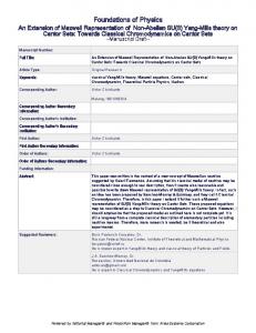
4.5 Using spreadsheets to calculate loadings To speed up calculations a computer spreadsheet can be used (Figure 4.39). (A basic knowledge of spreadsheets has been assumed.) Open a spreadsheet and save as ‘loadings calcs’. Then fill in the cells as listed below:
r Column A – cell A1 type: Roof materials r Column B – cell B1 type: Area (m2 )
4 Foundations
171
Building in the 21st Century
Roof materials
concrete tiles on battens sarking felt fibreglass insulation trusses @ 600 mm centres plasterboard and skim snow loading
Area (m2)
Load (kN/m2)
Total load
5.02 5.02 4.00 4.00 4.00 5.02
0.51 0.05 0.01 0.24 0.15 0.60
2.25 2.25 2.25
0.17 0.20 0.15
1.20
0.50
2.56 0.25 0.04 0.96 0.60 3.01 0.00 0.00 0.38 0.45 0.34 0.00 0.00 0.60 0.00 0.00 8.84 3.85 0.00 4.50 0.12 1.04 27.54
Floor materials
chipboard 19 mm floor joists plasterboard and skim Partitions (first floor)
timber stud External wall
clay brick (inc. mortar) Thermalite shield (inc. mortar) live load storage cistern foundation
5.20 5.20
1.70 0.74
2.25 2.00 1.00 0.12 1.00 1.04 total load per lineal metre
foundation type: trench fill 0.45 m wide x 1.00 m deep concrete @ 2300 kg/m3 length (m)
depth (m)
width (m)
1.00
1.00
0.45
density (kg/m3)
2300
load (kN/m)
1.04
[only half the load each end] 2.40 m / 2 = 1.20 m
kN/m
Figure 4.39 Loading calculations spreadsheet.
r r r r r r r
Column C – cell C1 type: Load (kN/m2 ) Column D – cell D1 type: Total load Column F – cell F4 type: Length (m) Column G – cell G4 type: Depth (m) Column H – cell H4 type: Width (m) Column I – cell I4 type: Density (kg/m3 ) Column J – cell J4 type: Load (kN/m2 )
The data that is entered in column C will be from trade literature or textbooks. Now enter the following: 1 Cell D2 should have the following formula entered: = (B2 ∗ C2) Then press ‘enter’. The data that is in cell B2 has now been multiplied by the data in cell C2. 2 Select cell D2 again. Using the left hand mouse button select the handle (a small grey square in the bottom right hand corner of the cell (Figure 4.40) and drag down to cell D23. Press ‘enter’ and the same formula will have been copied down into each line of cells using the relevant letter. (Always check that the formula is correct and working by entering simple numbers in cells in columns B and C). 3 Enter the following formula into cell J5: = (F5 ∗ G5 ∗ H5 ∗ I5)/1000 Dividing the answer by 1000 will show kilonewtons per square metre.
172
Building in the 21st Century
2
Left mouse click on handle and drag down to cell D23
4 Foundations
D =(B2*C2)
Figure 4.40 Spreadsheet handle.
4 Enter the following formula into cell C23: = J5 5 Enter the following formula into cell D24: = sum(D2 : D23) and press ‘enter’. The result should be as shown in the example. Now, by using the example spreadsheet as a template, you can enter your own data in the relevant cells to carry out other calculations. As you become more experienced in spreadsheet design you may use other formulae and protect cells from alteration, specifically the formulae cells. It is a good idea when designing the spreadsheet to create a file and save your work every ten minutes, say. Create a master copy and protect it, or form sheets within the spreadsheet, or create separate spreadsheets. If a major error occurs, you can always revert back to the original protected spreadsheet. Calculate the mass of a suitable foundation. In the example, 0.45 m wide and 1.00 m deep trench fill has been used. The total loading at the base of the foundation is 28 kN over an area of 0.45 m2 . The table in Approved Document A shows the imposed loading per lineal metre, not per square metre. So far we have a total loading for the structure in kN (force) per metre run. The initial ground survey would have identified the soil and subsoil/substratum of the site; CP 6399 (BS 6399) can be consulted for the bearing capacity or Table 4.2, reproduced from Building Regulations Approved Document A: 2004, can be used.
Foundation loading At the design stage the substratum type and bearing strength should be known (see Section 4.7). Based on the ground type a foundation design can be considered. In the example it is known that the soil is ‘firm clay’ so a trench fill foundation would be suitable. Assuming a minimum depth of 1.00 m (common
4 Foundations
173
Building in the 21st Century
Table 4.2 Minimum width of strip footings. Total load of load bearing walling not more than (kN/linear metre) 20 Type of ground (including engineered fill)
Condition of ground
Field test applicable
Rock
Not inferior to sandstone, limestone or firm chalk
Requires at least a pneumatic or other mechanically operated pick for excavation
Gravel or Sand
Medium dense
I
II
III Clay Sandy clay
Stiff Stiff
IV Clay Sandy clay
Firm Firm
V Sand Silty sand Clayey sand
Loose Loose Loose
VI Silt Clay Sandy clay Clay or silt
Soft Soft Soft Soft
VII Silt Clay Sandy clay Clay or silt
Very soft Very soft Very soft Very soft
30
40
50
60
70
Minimum width of strip foundation (mm)
Requires a pick for excavation. Wooden peg 50 mm square in cross section hard to drive beyond 150 mm
250
300
400
500
600
650
Can be indented slightly by thumb
250
300
400
500
600
650
Thumb makes impression easily
300
350
450
600
750
850
Can be excavated with a spade. Wooden peg 50 mm square in cross section can be easily driven
400
600
Note: Foundations on solid types V and VI do not fall within the provisions of this section if the total load exceeds 30 kN/m
Finger pushed in up to 10 mm
450
650
Finger easily pushed in up to 25 mm
Refer to specialist advice
The table is applicable only within the strict terms of the criteria described within it. Crown copyright: Building Regulations approved Document A: 2004, Table 10.
174
Building in the 21st Century
4 Foundations
in clay soils – see Section 4.12) and a width of 450 mm (0.45 m) enter the data in the ‘foundation type’ section of the spreadsheet. If you have written in the correct formulae and links, the total load per metre run (lineal metre) should be shown (28 kN/linear metre). Using Table 4.2, the lowest loading shown is 20 kN/linear metre. Go to the next loading up, 30 kN/linear metre. Look for the soil type in the left column, row IV Clay – Firm, and under the column headed 30 a recommended minimum width of 350 mm is given. Enter the data into the spreadsheet to compare the new calculated loading; however, it will not make a significant difference. The results suggest that the foundation width could be 350 mm, giving a considerable saving on the amount of spoil to be removed and fresh concrete required. If the structure is approximately 8.00 m × 6.00 m the saving would be about 3 m3 of concrete/spoil.
4.6 Foundation design theory Whatever pressures are acting downward they must be equalled by the pressures acting upwards (Figure 4.1). All materials have a mass. Mass is a term for the number of molecules that make up the material or substance. The molecules are attracted towards the centre of the Earth by a force known as gravity. Generally, all molecules are pulled downwards with an acceleration of 9·81 metres per second per second (m s−2 ). For example, a lump of stone with a mass of 1 kg released from the top of scaffolding will fall towards the ground with an acceleration of 9.81 m s−2 ; after 3 seconds it will be travelling at a speed of 3 × 9.81 = 29.43 m s−1 . Sir Isaac Newton in 1666–67, after watching an apple in an orchard falling towards the ground, developed a theory suggesting that there must be an attraction which pulls the apple downwards. In 1960 the UK adopted Syst`eme Internationale (SI) units of measurement and named the unit of force in Newton’s honour; in Example 1 we find that a force of one newton is approximately equal to the force of gravity acting on a four ounce apple. However, 1 newton (N) is actually defined as the force that, when acting upon a mass of 1 kilogram, produces in it an acceleration of 1 m s−2 . Gravity produces an acceleration of 9.81 m s−2 so the force on a 1 kg mass is 9.81 N; however, in construction calculations we use a loading of 10 N/kg.
Example 1 (see Figure 4.41) An apple has a mass of 100 g (about 4 ounces in imperial units). The mass multiplied by the force of gravity will equal the weight. Weight = Mass × Force of gravity Express the mass as part of a kilogram 100 g = 0.1 kg
4 Foundations
175
Building in the 21st Century Figure 4.41 Gravitational pull.
For simplicity, assume that gravity produces an acceleration of 10 m s−2 . Then, Weight = 0.1 kg × 10 N/kg = 1 N
Example 2 What would be the imposed load (downward force) from 5.02 m2 of concrete tiles on battens with a mass of 51 kg/m2 ? The calculation is as follows: Area of material expressed in m2 ×Mass expressed in kg m−2 ×Gravity = Force For simplicity, assume that gravity produces an acceleration of 10 m s−2 . Then, 5.02 m2 × 51 kg m−2 × 10 N/kg = 2560.2 N/1000 = 2.56 kN Answer: the loading is 2.56 kN (note that no unit of area is shown).
4.7 Ground surveys There are several methods depending on the size of the project and the topography of the land, both the plot and the local conditions. The historic use of land is an important issue in relation to buried hazardous waste, landfill, mining, quarrying, etc. (see Section 4.8). The usual ground level surveys are:
r trial pit r borehole However, aerial photography using digital cameras and thermal imaging cameras can provide good sub-terrain information by means of hot spots and variation in the colour of foliage. The subject is beyond the scope of this book.
176
Building in the 21st Century
4 Foundations Figure 4.42 Section through a trial pit.
Trial pit tests Where access is simple, a trial pit is dug either by hand or excavator up to 1–1.5 m deep to expose the substratum. This method enables an experienced surveyor to measure and record the type(s) of strata in-situ (undisturbed – where it is). If the water table is higher than the trial pit formation level, it should be left for a day to stabilise (the pit should be adequately protected if left open overnight both to prevent accidental falls (the contractor has a duty of care under the Health and Safety at Work Act 1974) and to prevent rain filling the excavation and giving a false level). The trial pit should be clear of the intended foundation lines as it will weaken the ground locally. However, caution! As the drawing in Figure 4.42 suggests, the stratum could change in thickness or type within metres of the trial pit. Examples of ground surveys going wrong include a historic rubbish pit in East London not found by the survey that required the design of foundation for two storey sheltered accommodation to change from 1.5 m deep trench fill to at least 2.5 m during trench excavation. In Essex, running sand adjacent to a river was completely missed on the survey which added an enormous bill to the client when the work proceeded.
Borehole tests On larger projects or where access is restricted, borehole testing can be used. Depending on the size of the proposed structure and the expected soil type, a small borehole can be used, or alternatively where deep pile foundations are required, a piling rig borehole will be needed.
4 Foundations
177
Building in the 21st Century
Figure 4.43 shows an impact borehole logger. A heavy metal weight is regularly dropped onto a shaft pushing the bore shell into the stratum. When the shell is filled it is extracted, recorded and set aside for study. The procedure is repeated with an empty shell to record the next level of stratum. Figure 4.44 shows the geologist inspecting the soil sample and bagging it for further chemical analysis in the laboratory. This particular test was carried out next to a river in Colchester to advise a developer of the soil conditions. Note the PPE being worn: high-viz jackets, highviz waistcoats, hard hats, protective footwear and gloves. Only the technician operating the machine required additional ear defenders and eye protection. Land near historic rivers can be particularly troublesome due to deposits from the water. Typical problems include running sand next to the River Chelmer in Chelmsford and alluvium in localised land next to the River Rom in Romford. Both soil types had been missed during the ground survey, but added enormously to the time and cost when the projects proceeded. Running sand, when held in place by its surrounds, can be suitable to build on. The problem is the method of excavation required and how thick the Figure 4.43 Drop hammer soil sampling. layer is. If an open trench method is used the sand will continually flow into the trench with possible cave in/subsidence of higher levels of strata. The solution used on the specific site comprised a steel sleeve impacted through the running sand into the clay beneath. The contents of the sleeve were augured out using a standard piling auger and a concrete pile was cast inside the sleeve (Figure 4.45).
4.8 Desk top surveys Before surveying an area it is useful to gather as much data as is known in the office. Maps produced by the British Geological Survey can be particularly useful: these indicate the geological structure of the whole of Great Britain but not the soil types (the overburden); they can be found in the National House Building Council (NHBC), the Building Research Establishment (BRE), British Standards and Eurocodes. If the project is small, there are companies which, for a fee, will provide data about the historic and current use of the land. The data has been based on surveys in the area, any major excavations, and local authority records. It should be borne in mind that desk top surveying can be
178
Building in the 21st Century
4.9 Foundation materials
4 Foundations
useful as a guide for preparatory work; however, it should not be used as definitive or accurate (Figure 4.46).
Concrete mixes Concrete has been used since early Roman times. The Pantheon in Rome built in the year 118 AD has a 43 m diameter dome capped in early concrete. After the fall of the Roman Empire, the art of cement making was lost for centuries until, in 1756, John Smeaton used a type of cement to bed the rock used for the Eddystone lighthouse. Shortly afterwards, in 1824, Joseph Aspdin patented cement used to make concrete. The new concrete material looked similar to the popular limestone from Portland, so he named his cement ‘Portland cement’. Cements that are used in the production of concrete and mortar are known as binders. Their function is to prevent the particles (both fine and coarse) from moving, so it is essential that the materials are well mixed and that the cement paste completely envelops all surfaces. Concrete comprises: Figure 4.44 Geologist inspecting an undisturbed soil sample.
Steel sleeve
1 Binder (Portland cement) 2 Aggregates (coarse and fine) 3 Water (it should be potable – drinkable)
Concrete
Borehole
Running sand Soft clay Firm clay
Figure 4.45 Piling through running sand.
4 Foundations
179
Building in the 21st Century Figure 4.46 Desk top survey for historic information.
(see Figure 4.47). The proportions vary for different types of concrete, but in general terms are based on the number of voids in the aggregates: sand, 33.3%; gravel, 45.0%. There are three main ways concrete can be specified: 1 nominal mix 2 prescribed mix 3 designed mix.
Nominal mixes Nominal mixes are produced on a ratio basis such as:
r 1:3:6 r 1:2:4 180
Building in the 21st Century
4 Foundations
The first number refers to the volume of cement, the second number is the volumes of fine aggregate (sand), and the last number the volumes of coarse aggregate. If the coarse aggregate has, say, 50% voids and there are six volumes, then the three volumes of sand will fill them. However, the one volume of cement will fill 30% sand voids.
Prescribed mixes The required strength is stated in newtons per square millimetre (N/mm2 ):
r C7P – mass foundations equal to a 1:3:6 mix
r C10P – as C7P but can be used in wet conditions
r C15P – general mass use, minimum strength for structural unreinforced work
r C20P – general floors and reinforced work equal to a 1:2:4 mix
r C25P – used where the exclusion of water Figure 4.47 Main components of dense concrete.
is necessary
r C30P–for moderate abrasion resistance of a concrete floor (equal to 1:1 12 :3).
The C stands for compressive (the required final strength at 28 days), the number relates to the strength in N/mm2 , and P means the mix is prescribed. A series of mix designs were developed by the Department of the Environment (DoE) and the Cement and Concrete Association that enable the specifier to state the mix design in great detail using a DoE sheet.
Designed mixes These can be specified. The contractor or manufacturer is responsible for achieving the required strength. This method is now common for foundation concrete. However, the specifier should state which type of cement and any other properties the concrete should have, or any additives required. Alternatively, GEN1 (designated concrete), ST2 (standardised prescribed concrete), or S3d (recommended consistence class) can be used. The mixes shown above are defined in BS EN 206-1 as suitable for housing and other applications. Where reinforcement is required, the mix strength and density increases to RC30 or FND2 as designated concrete. Concrete floors range from house floors (oversite slab) without reinforcement as GEN1, to a garage floor as GEN3 (Table 4.3). For harder wearing surfaces such as industrial floors, RC50 would be specified. The recommended consistency for the whole range of floors is S2.
4 Foundations
181
Building in the 21st Century
Table 4.3 Common design mixes of dense concrete. Designated concrete
Required strength class
Compressive strength (N/mm2 )
Default slump class
GEN1
C8/10
10
S3
GEN2
C12/15
15
S3
GEN3
C16/20
20
S3
FND (all designations)
C16/20
20
S3
RC30
C25/30
30
S3
RC50
C40/50
50
S3
Standardised prescribed ST1
C6/8
8
ST2
C8/10
10
ST3
C12/15
15
ST4
C16/20
20
ST5
C20/25
25
ST mixes should not be used where sulfates or other aggressive chemicals are present. In such instances FND concrete should be specified. Where concrete is likely to be exposed to freeze–thaw cycles and possible de-icing salts, such as on drives, roads or footpaths, an air entrained concrete should be used. The concrete should be ‘designated concrete’ design. The BS EN 206-1 code provides guidance regarding the minimum cement content required for specific diameter aggregates, and water/cement ratios. The common coarse aggregate diameter is 20 mm, and the water/cement ratios 0.5 and 0.6 require 320 kg/m3 and 280 kg/m3 , respectively. Figure 4.48 shows a typical concrete used for foundations.
Aggregates Coarse aggregates as shown in Figure 4.49 are from quarried glacial deposits formed during the last ice age. Note the smooth surfaces of mainly flints which are common in the south east of England. As the ice thawed, the aggregates were transported by rivers into ancient shallow seas and were rounded off in the process. The small particles that broke off became the sands and with chemical breakdown separated into quartz and silicates that became sand and
182
Building in the 21st Century
4 Foundations
clays. Large deposits of rounded stones with layers of sand and clay will be found in many areas of the south east of England. They tend to be rounded flints, quartz and some sandstone. Many of the exhausted quarries have been used for landfill sites to bury waste (see Chapter 10). In the UK, over 100 000 000 tonnes of aggregate are used every year. Each year, access to local aggregates is reduced. Many large beds of aggregates cannot be quarried as there are now roads and buildings covering the land. Environmentalists do not want farmland, woodlands and areas of natural beauty changed for ever; therefore planning laws restrict further new quarries from being opened in the south. However, the government is committed to building at least 120 000 new homes by 2016 in their Thames Gateway project which will need an estimated 7 200 000 tonnes of aggregates. Figure 4.48 Saturated dense concrete. What other resources are available? Basically rocks and waste. Rocks in the form of mountains are being systematically broken up and transported by sea to the south of England and parts of Europe. In the north west of Scotland, Foster Yeoman Glesanda have been quarrying 6 000 000 tonnes of rock per year from a mountain, crushing it and shipping it to the Isle of Grain in Kent (Figure 4.50).
Figure 4.49 Coarse natural dense aggregates.
4 Foundations
183
Building in the 21st Century Figure 4.50 Aggregate wharf and the one of the Foster Yeoman self discharging vessels. Photograph by Samantha Cooke.
From there they transport it by train or road to much of the south east of England. About 5 000 000 tonnes of crushed limestone is brought out of the Mendip quarries in the south west of England by train or road. Crushed aggregates are less workable but have the advantage of greater compressive strength. Sea dredged aggregates are frequently used on the south coast of England. They have to be washed in fresh water to remove the salt.
Types and shapes of aggregates There are six main shapes: most are shown in Figure 4.49. Numbers 1, 2 and 3 will give better compaction and workability than 4, 5 and 6. If the rocks have been split they will tend to be angular and therefore difficult to work (of low workability). Figure 4.51 shows crushed limestone from the Derbyshire area: note the rough surfaces and angular shapes. Aggregates used in foundation concrete include coarse aggregates ranging from 5 mm diameter (Ø) up to normally 40 mm Ø. For general concrete foundations (with or without reinforcement) 20 mm Ø and sharp sand would be used. Sand ranges from almost dust to 5 mm Ø. Sizes above 5 mm are defined as gravels and coarse. Sands are classified into zones. Each zone has a specific ratio of particle sizes. The test is carried out using a nest of sieves, a sieve vibrator and balances. The ratios will affect the porosity of the mix, workability and the water content, as well as the cement proportion and/or content.
184
Building in the 21st Century
4 Foundations Figure 4.51 Crushed limestone dense aggregate.
General requirements Aggregates should be clean and free from sulfates, salts and organic matter (also some reactive silica which causes ‘alkali aggregate reaction’ – commonly calcium alkali silica which absorbs water and therefore makes the concrete more vulnerable to frost attack or rusting of reinforcement). Flaking of aggregates, clay and silt should be carefully monitored and not exceed the requirements of BS 882. Aggregates should meet the following requirements:
r r r r r
be free of any coatings be chemically inert and stable must not corrode or decompose be free from expansion will not cause staining.
Aggregates are normally washed before delivery, and this is essential where sea dredged aggregates are being used. Salt is very corrosive and if contained in the concrete it will (when water is present) eventually cause it to fail. All-in ballast is a mixture of fine and coarse naturally occurring aggregates. These require balancing before they are used for the production of concrete. Ballast should not be used for quality concretes.
Density Density is an important property of both aggregates and finished concrete. Density (relative density), formerly known as specific gravity, is the mass of a given volume of aggregate compared with the mass of an equal volume of water at 20◦ C. This is important as it enables mass to be compared with volume – batch mixing uses the technique where so many kilograms of aggregate and cement produce so many cubic metres of concrete. Relative density (RD) is divided into three classes to take into account that the aggregate could be porous, so there will be three possibilities:
4 Foundations
185
Building in the 21st Century
1 Oven dry – no water in it or on it Oven dry RD = mass of dry aggregate/volume of aggregate including pores 2 Saturated but dry – dry aggregate with all the pores filled to saturation point (also known as SSD–Saturated aggregate with the Surface Dry) RD = (mass of dry aggregate + water in pores)/ volume of aggregate including pores 3 Apparent relative density – where the aggregate is considered as a mass and volume not considering the pores RD = mass of dry aggregate/solid volume of aggregate The density range of most natural aggregates used for foundation concrete is 2000–2400 kg/m3 ; they will have a crushing strength of between 14 MN/m2 and 100 MN/m2 .
Portland cement Making concrete The chemical reaction starts after the water has been added and a paste is formed. The paste goes through two stages: 1 Stiffening or setting (initial and final). The correct amount of water is required to hydrate cement, any excess will only create air voids when it evaporates and therefore weaken the bonding. When the chemical reaction starts, a latticework of crystals forms. At an early stage (about 2–3 hours after the water has been added) the crystals grow. If the fresh concrete is knocked, frozen, or more water is added, the crystals will rupture and lose their strength. 2 Hardening when the useful strength is developed – this is hydration. The water/cement ratio is important. Listed below are some things to be considered:
r cement requires the correct amount of water to produce and complete the chemical reaction
r too much water will weaken the final product r too little water may result in the chemical reaction stopping before it is complete
r concrete needs to be workable – required workability depends on its use r ambient temperatures may affect the chemical process. When the water is added the subsequent chemical reaction is exothermic and produces heat. In cold weather this heat can help the curing process which ceases at about 0◦ C (2◦ C is the cut off figure), but in summer the excess heat can lead to thermal stress and/or differential stresses which can cause thermal
186
Building in the 21st Century
Hour
1
Setting period 2
6
Hardening period
12
Days
1
2
28
7
4 Foundations
Dormant period
Figure 4.52 Concrete setting periods.
cracking in mass pours. Specialised cements or additives can overcome some of the problems of heat generated by the exothermic reaction.
Hydration period Figure 4.52 shows the typical hydration period for Ordinary Portland cement.
Portland cement types Ordinary Portland cement Ordinary Portland cement (OPC) is the cement most commonly used for concrete, mortars and products such as concrete blocks. There are different versions of OPC – bagged or bulk – giving different strength classes after 28 days’ curing: OPC bagged at 42.5 N/mm2 and CEM I bulk up to 52.5 N/mm2 . OPC is vulnerable to sulfate attack and therefore if it is known that the soil pH is above 5.5 and therefore acid, OPC must not be used. The elements calcium and silicon are found in chalk and limestone, clay or shale. Clays often contain large quantities of aluminium and iron compounds which give the characteristic grey colour to OPC. The proportions of these compounds in the cement can be modified to produce specific cement types, such as sulfate resistant cement, or white cement used for decorative concrete. Clay with a low content of aluminium or iron compounds is used for white cement. The four main compounds obtained from the clay or limestone used as raw material are shown in Table 4.4.
Table 4.4 Chemical composition of Portland cements.
4 Foundations
CEM I [42.5N] SRPC White Portland (%) (%) cement (%)
Compound
Short formula
Rate of hardening
Tricalcium silicate
C3 S
Rapid
56
64
65
Dicalcium silicate
C2 S
Slow
16
10
22
Tricalcium aluminate
C3 A
Rapid
8
2
5
Tetracalcium aluminoferrite
C4 AF
Extremely slow
9
14
1
187
Building in the 21st Century
Table 4.5 Setting strength comparison between OPC and RHPC. Setting strength (N/mm2 ) Time after mixing (days)
OPC
RHPC
3
13.0
18.0
28
29.0
33.0
The strength of the cement is measured at the early age of 2 days and then at 28 days, and should not be confused with the strength of the concrete or mortar tests (Table 4.5).
Rapid hardening Portland cements Similar to the clays from which it was derived, cement expands when wetted. The quicker the water can activate the cement, the faster the process can work. To speed up the reaction time, OPC is ground down to produce smaller particles and therefore, for the same mass of cement, a larger surface area for the water to reach, giving rapid hardening Portland cement (RHPC). OPC has a surface area of 300 m2 /kg, whereas RHPC has a surface area of approximately 400 m2 /kg – this is known as its specific surface. RHPCs are now defined as CEM I 52.5 (where 52.5 indicates the compressive strength in newtons in given time limits). A slight variation to the formulation is also made. Because CEM I 52.5 also produces heat more quickly than OPC, it is useful in cold weather. The initial and final setting times of RHPC are the same as for OPC. However, the compressive strength after 3 days is dramatically increased. The disadvantages of RHPC are that, because it produces much more heat, pouring large volumes in the summer months can be problematic. RHPC also has low resistance to shrinkage cracking and sulfate attack.
Portland supersulfated and high alumina cements These are both used in the construction industry, but must not be used for structural concrete.
Sulfate resisting Portland cement Sulfate resisting Portland cement (SRPC) has a reduced tricalcium aluminate content (C3 A less than 3.5%). It is suitable for foundations and certain concrete applications where groundwater has a concentration of sulphur trioxide up to 0.1% or subsoils contain up to 0.5% SO3 . This cement is commonly specified for foundations in clay or gravel areas, such as Essex and London, where pockets
188
Building in the 21st Century
Low heat Portland cement (BS 1370)
4 Foundations
of sulfates are present. Soil tests or local knowledge, such as from a building control officer, will ascertain whether it is needed.
This cement is low in C3 S and high in C2 S and C3 A; it is finely ground but by changing the content of certain constituents slows the hardening down and thus the release of heat. It is used when pouring vast volumes of concrete. Whereas OPC generates about 400 kJ/kg in 28 days, LHPC produces 290 kJ/kg in the same time period.
Masonry cement Masonry cement is OPC with added chalk or silica and a plasticiser. It is used where a workable mix is required without the addition of lime which can stain certain brick types.
Blastfurnace slag cement Granulated blastfurnace slag (GGBS) is a waste product from quenching selected molten blastfurnace slag from iron smelting. It can be blended with CEM-1 to produce a sulfate resistant concrete. Portland-slag cement CEM II/A-S contains between 6 and 35% slag. Benefits include good resistance to dilute acids and sulfates, it is cheaper than SRPC and ideal for sea walls, etc.
Commercial concrete manufacture (Figure 4.53) The bulk materials are stored in bays ready for mixing in a batching plant. The bin shown in Figure 4.54 has coarse aggregates and that in Figure 4.55 has the fine aggregates. A loading shovel deposits the aggregates into a hopper which feeds a conveyor belt taking them to the bulk silos (Figure 4.56). Figure 4.57 shows the main parts of the process. A computerised weighing machine weighs and dumps the aggregates onto a screw drive transferring them to the mixing drum. The batcher can monitor the entire process on the computer screen (Figures 4.58 and 4.59). The left hand dial shows the total amount of cement and the right hand dial the aggregates going to the mixer. In this case the concrete will be resistant to ground sulfates. Water is also measured by weight: 1 litre of water weighs 1kg, so the whole process can be monitored by weight. This information is important to the lorry driver to prevent overloading. The workability of the concrete is influenced by the aggregate shape, size, ratio of fine to coarse, and the amount of water it contains. Trial mixes are produced and all the factors recorded. The workability of a concrete is the ease with which it can be placed. For example, a trench fill foundation will require
4 Foundations
189
Building in the 21st Century Figure 4.53 Fresh concrete batching process.
a workable (relatively fluid) mix that flows along the trench with some help from the ground workers. However, it should not be so wet that it self levels. A method of quantifying workability is to state the amount a mix slumps (see p. 195, Slump test). The mixed concrete is transferred to the transit vehicle ready to be delivered to site (Figure 4.57). Although a relatively small batching plant is shown, the process is similar in larger plants. Special mixes can be produced on request with additives to retard or accelerate setting, reduce water content, or using special aggregates. Batching plants tend to be located close to built up areas to reduce the transit time of the mixed concrete. Some remote contracts have the water added to the mix whilst the transit vehicle is en route.
190
Building in the 21st Century
4 Foundations Figure 4.54 Coarse aggregate bin.
Figure 4.55 Fine aggregate bin.
Concrete for foundations Site procedure Small quantities of concrete for, say, a house extension may be made manually on site. Generally the concrete will be made to a nominal mix method. The
4 Foundations
191
Building in the 21st Century Figure 4.56 Conveyor and hopper heads.
Cement
Water added at the mixer
Aggregates
Transit vehicle
Figure 4.57 Batching mixer.
strength of the foundation must exceed 7 N/mm2 so a 1:3:6 (20 mm Ø) mix should be adequate. Table C.1 of BS EN206-1 gives a target cement content for common foundation mass concrete applications.
r 1:3:6 mix should have 190 kg/m3 of cement r 1:2:4 mix would have 275 kg/m3 .
192
Building in the 21st Century
4 Foundations Figure 4.58 Materials data monitor.
Figure 4.59 Materials monitor.
Site procedure All-in ballast is commonly used at a ratio of 1:5 where the supplier has blended the sand with coarse aggregates before delivery. The process on site should be as follows: 1 Provide a flat clean area off the public highway to take delivery. Ideally boards should be used to prevent the aggregates from becoming contaminated with soil.
4 Foundations
193
Building in the 21st Century
2 Cover the aggregates if they are to be left overnight as rain can wash the sand from the ballast. 3 Provide a firm level surface for the concrete mixer. The three main types of mixer are powered by: r electric motor (it must run at 110 V so either from a transformer or generator) r petrol engine r diesel engine. 4 A supply of clean potable water. 5 Container to deposit packing and cleaning waste (commonly a skip). Mixing method 1 Switch on mixer and let it run empty. 2 Using a shovel place five regular shovels full of aggregate into the drum. 3 Place one regular shovel full of cement. (If windy, place the mixer down wind to stop the cement powder blowing in the operator’s face). 4 As the mixer blades fold the aggregates and cement together add the water gradually. When the mix falls away from the drum by gravity do not add any more water. (It is useful to use a bucket for the water so that the quantity added can be gauged each time.) 5 Turn out the mix into a wheelbarrow ready for it to be taken to the foundation trench. Textbooks suggest a gauging box be used to regulate the quantities of aggregate and cement. Whilst obviously it will be technically accurate, it is impractical and rarely done on site.
Testing fresh concrete and aggregates There are two types of test: 1 On-site r field settling test r slump test 2 Off-site r RD test r destructive compressive test using sampled test cubes r compaction factor test r Vebee test.
Field settling test On site, fine aggregates (sand) should always be tested for cleanliness. The official test is shown below, but an old jam jar (as long as it is clean and of clear glass) can be used. The object is to determine the percentage of silt held with the sand. Looking at the sand will not help as the silt particles will be less than 150 μm wide. If the sand has been deposited for several days, select a sample
194
Building in the 21st Century
4 Foundations Figure 4.60 Field settling test.
from the top, middle and bottom of the pile and mix in a bucket (if the sand has just been delivered use any sample). 1 Place mixed sample in the glass container and pour clean water to cover by about 25 mm. 2 Cover the top and shake the sample ensuring all of the sand is mobile. 3 Leave on a flat surface for about an hour to settle out. (Half a teaspoonful of salt will speed up the settlement of the smallest particles otherwise wait until the water is clear.) 4 Measure the amount of silt which will appear as a fine yellow/orange layer on top of the sand and express as a percentage of the sand and silt. 5 If the silt percentage is about 8–10% of the total solids then repeat the test. If the percentage exceeds 10% contact the supplier as the sand is too polluted to be used. The laboratory test is virtually the same; however, it has to be carried out in accordance with the relevant British Standards (see Figure 4.60).
Slump test To test the workability of fresh concrete on site before it is used, a slump test should be performed. If the fresh concrete has been made off site in a batching plant, it may have been delayed in traffic. It is important to record the time of arrival and check the delivery ticket for the time it was originally mixed. (Remember that the cement will start to form crystals between two and three hours after mixing, depending on the weather, and that a late delivery will
4 Foundations
195
Building in the 21st Century Figure 4.61 Slump test.
reduce the placing time on site.) The slump test will indicate how workable the mix is and whether it has been rewatered en-route. (Reputable ready mixed concrete operators would not carry out this bad practice; however, experience has shown that it does take place.) Method (Figure 4.61) 1 Deliver a small sample from the transit vehicle into a wheelbarrow or dumper truck – transfer it to a bucket if required. 2 Prepare a flat clean surface and stand the slump cone on it. 3 Stand on the two foot tabs (or ask an assistant to hold the handles to keep the cone firmly in place). 4 Using a scoop or brick laying trowel, deposit the fresh concrete into the open ended cone to about the 75 mm level. 5 Using the tamping rod round end downwards, rod 25 times to remove any trapped air voids. 6 Repeat the procedure at the 150 mm level and tamp 25 times. 7 Repeat the procedure at the 225 mm level and tamp 25 times.
196
Building in the 21st Century
Slump test from initial discharge Specified slump class
Minimum (mm)
Maximum (mm)
S1
0
70
S2
30
120
S3
80
180
4 Foundations
Table 4.6 Concrete workability.
8 Finally fill the cone (300 mm) and tamp 25 times. 9 Flush off the top with the trowel, and carefully remove the cone by slightly twisting it vertically to help it release. 10 Invert the cone and stand it next to the sample; place the tamping rod across the wide end of the cone and over the sample. 11 Measure the difference (if any) between the underside of the tamping rod and the top of the sample: this is known as the slump. The greater the slump, the more workable the mix. Slump testing fresh concrete from an initial discharge has an upper and lower limit. Where, for instance, a stiff mix is required a specified slump of up to 40 mm can range from 10 mm to 80 mm at time of discharge. Again a specified target slump of 50 mm to 90 mm could range from 10 mm to 140 mm. Although concrete is a complicated material its manufacture is dependent on many factors; therefore the batcher’s experienced eye still is considered the best gauge. Eurocode EN 12350 for testing fresh concrete identifies slump ranges for a specified slump class. Some commonly used slump ranges are shown in Table 4.6.
Some useful British Standards and Eurocodes EN 1992 (Eurocode 2) EN 206-1 EN 12350 EN 12390 EN 13591 EN 834-3 EN 12620 BS 8500-2:2002
Design of concrete structures Concrete Testing fresh concrete Testing hardened concrete Assessment of concrete strength in structures Admixtures for concrete Aggregates for concrete Covers aggregates
4.10 Health and safety issues relating to concrete and cement Portland cement is alkaline. When activated with water it can burn skin tissue. Cement dust is an irritant and can be breathed in when the operator places the cement into a working mixer. (The risk can be reduced by locating the mixing area in a sheltered place or with the mixer downwind of the materials and
4 Foundations
197
Building in the 21st Century
operator. This should be part of the risk assessment required by the Health and Safety at Work Act 1974. A first aid box and eye washing bottle should be easily to hand, either in the site hut or, on small jobs, in the van. Appropriate personal protective equipment should be worn. The Act states that it is the duty of everyone to be responsible for their own health and safety and those around them. This means that not only does the employer have a duty of care for all operatives and anyone on or near the work, but the operatives also have a duty to themselves. When working with cement dust in bags, the working area should be sectioned off or far away from the public, including neighbours, to prevent the wind blowing the dust over them or their property. The use of solid hoarding will prevent dust leaving the site (see Chapter 9, Section 9.3).
Personal protective equipment In recent decades it has become commonplace for concrete workers to wear as little as possible in the summer months, shorts and trainers being popular. However, accidents and poor health have been rife in the building industry, a situation that the Health and Safety Executive is trying to rectify. Larger sites employ safety officers and consider health and safety as a major issue. Training is required and qualified management ensures that health and safety is the number one concern of everyone. In contrast, smaller builders carrying out small works such as building extensions and single houses often employ subcontractors. By the nature of the job it would be impractical to carry out induction briefs and tool box talks. Many subcontractors may have either limited training other than for their trade, or their training was undertaken many years ago and is now out of date. The Health and Safety at Work Act does not differentiate between one person’s health and safety and another’s. All personnel working with cement or fresh concrete should wear the following: 1 2 3 4
Leg cover (trousers or boiler suits). Arm and body cover (shirt or boiler suit). Eye protection (polycarbonate spectacles). Stout site footwear (steel toe protection, water resistant, sole protection). There are many designs and styles ranging from rigger boots to trainerlooking site wear). 5 Gloves (several different types of glove are available). For those placing the concrete, a gauntlet style rubber glove will prevent fresh cement splashing the wrists or falling into the gloves. Cheap washing up gloves will provide some protection. Cotton lined rubber gloves are more comfortable to wear and reduce the wet hand problem caused by sweat. 6 A hard hat should be worn if there is any overhead working. 7 Sun tan barriers. If working outside in direct sunlight for long periods it is now recommended that sun tan barriers are used. The levels of ultraviolet light getting through to England are increasing as part of climate change; therefore it is considered good policy to put a barrier over the skin to reduce the possibilities of skin cancer in later life.
198
Building in the 21st Century
Faulty foundations cost the construction industry and insurance industry in excess of 300 million per year in claims. The greatest failure is caused by tree roots and chemical attack. Tree roots were mentioned in Section 4.1; however because of their importance, further comment is required.
4 Foundations
4.11 Problems with foundations
Tree root problems The following questions need to be asked: 1 What species of tree are present, how old are they, what is the soil condition and what are the weather conditions? 2 Who owns the tree(s)? 3 Were the trees there before the foundations? 4 Were there trees on the site before it was cleared? 5 What is the type of ground/substratum – made up, green field or brown field? 6 What is the topography? The six issues above are not the only ones that affect foundations. For example, consider the following scenario. A large house and garden have been sold to a developer who intends to demolish the house and build three new detached dwellings. The garden contains several mature apple trees and cherry trees in the area to be occupied by the new buildings. The soil is clay to a depth of 2 m over a bed of ballast of unknown thickness. The builder has a specialist demolition company remove the old house and shallow foundations. (It was common for old houses to be built on foundations only 450 mm deep, even in clay soils.) The houses to each side of the plot both have mature oak trees on their property within 2 m of the boundary. The site is on a hill near to the bottom of a small valley in an area that has been developed since Victorian times. How will the issues raised above affect the design and the construction of the new development? 1 The mature apple trees have been removing vast quantities of groundwater over a very long period. If the builder removes the trees where will all the water that would have been evaporated by the trees now go? In a clay soil it most likely that it will cause ground heave. 2 When the ground survey was carried out, what was the time of year and what weather conditions prevailed? If, say, the survey had been in March after a relatively dry winter the groundwater table may have been abnormally low. As the site is near the bottom of a hill in a valley there will be a tendency for the water to lie near the site. Was there once a river or brook running in the valley? Has it been filled in or diverted? (Old maps may help, even elderly neighbours are a good source of knowledge. They may remember fishing in the brook, river or pond when they were young.) 3 What about the old foundations? When were they grubbed out (removed) and how deep did the excavator dig? If it was less than the
4 Foundations
199
Building in the 21st Century
depth of the new foundations there should not be a problem; however, if not, the soil will now be weaker in that localised area. 4 The oak trees on the neighbours’ land will not recognise the site boundary. If the builder cuts significant tree roots that have gone across the legal site boundary, the tree may become unstable and topple during any future high winds. Cutting the roots may harm the tree and cause damage; therefore a specialist should be consulted before any pruning of tree roots takes place. As the trees are oak, they are probably the subjects of tree preservation orders which makes it illegal to prune, remove or otherwise damage them, whoever’s land the roots are on. The local authority should be approached for guidance on the matter. It is not a case of trimming the tree roots or branches back and offering them back to the owner. 5 The trees are mature which means they must be at least 50–60 years old, and possibly well over 100, so the builder cannot say they damaged the new foundations. The designer should have taken the tree roots into consideration. 6 We know that the apple and cherry trees were still in place before the demolition took place, so it is unlikely that other roots will be found in the same area. What options are open to the designer for the new foundations? Clay soil means it is likely to swell and shrink when the seasons change. (Not all clays swell at the same rate; indeed some clays are impervious to water and do not move.) Tree roots are going to seek water; as the climate is changing it is predicted that winters will become less wet or cold and droughts will become more regular. What foundation will
r allow for near surface expansion of soil? r not act as a barrier to any ground water movement? What else does the designer need to know?
r how thick the layer of ballast is below the clay r whether there are any sulfates in the ground or groundwater.
Chemical attack What are sulfates and why are they in pockets or localised areas? Sulfates are concentrations of acid rain. Acid rain has existed for as long as water has been on Earth. As volcanoes erupt and faults within the Earth’s surface spew vast volumes of sulfur dioxide (SO2 ) into the atmosphere the gas combines with moisture in the air to form sulfuric acid – acid rain. On clay areas the rain was unable to percolate into the ground and formed ponds. As the water evaporated, the solution of acid became more concentrated. The cycle regularly repeated itself over many years developing into localised areas of concentrated acid rain. Where areas were exposed and dried out completely, crystals formed which look like small bright granules of sugar. During long periods of drought the crystals became covered and eventually trapped beneath the ground. Unless the groundwater can dissolve the hardened crystals they
200
Building in the 21st Century
4 Foundations
remain unchanged for thousands of years. The process is very slow but is still taking place in areas with high pollution levels such as Eastern Europe. What will the sulfates do? They have little effect on most plants and materials; however, Portland cement will react with sulfates. A reaction occurs between tricalcium aluminate in the cement and the soluble sulfates in the clay, or flue condensate carried by continuous saturation in water. The reaction produces ettringite (hydrated calcium sulfoaluminate) which occupies a larger volume and is weaker than the cement from which it came. Sulfates are present in London clay, lower lias, Oxford clay, Kimmeridge clay and Keuper marl. Other sulfates include calcium sulfate (gypsum), magnesium sulfate, and sodium sulfate. Some clay bricks contain enough sulfates to be troublesome. Sulfate attack first hardens the brickwork mortar and then turns it into a white powder. The surface may be hardened by atmospheric carbonation and appear to be normal. Brickwork subjected to frost can increase the problem. If there are known sulfates in an area, SRPC should be used for masonry under dpc level (substructure) and for the concrete foundation. As an alternative, GGBS may be blended with the SRPC to reduce costs and reduce the heat output of the exothermic reaction in hot weather. (see Section 4.9).
Answer to design issues When the designer knows how thick the layer of ballast is (borehole testing is required) it is likely that a structural engineer will detail a short bored pile and beam foundation with SRPC and possibly steel reinforcement to prevent horizontal shear as the site is on a hill. The Building Research Establishment and the National House Building Council have both published information about building near trees.
4.12 Soils and substrata Substrata are classified into five main groups: 1 2 3 4 5
rock non-cohesive soil – gravel and sand cohesive soil – such as clay peat and shifting sand made ground or fill.
Rock There are three main rock types:
r igneous r sedimentary r metamorphic. Igneous rocks form as a skin on the molten mantle. They are generally dense and crystalline in structure. Granite and basalt are perhaps the most common
4 Foundations
201
Building in the 21st Century
igneous rocks in the UK and form the bedrock. Beneath areas where the granite is near to the surface, such as the West Country and parts of Scotland, radioactive deposits of uranium are present. As the uranium decays radioactive radon gas filters through the stratum and eventually into the air. This natural process has only recently caused concern. The gas can percolate through concrete and fill voids beneath floors in buildings. As modern building techniques have reduced draughts and suspended floors have become popular, the gas has tended to become more concentrated within structures and is thought to have increased certain types of cancer. Consequently the Building Regulations now specifically mentions radon gas as a problem that requires installation of specialist barriers and vents. Where the igneous rocks weather, they fragment into free rocks of various sizes from boulders down to sands. Chemicals within a stratum can be washed through cracks in the rocks at high temperature; the solution is highly corrosive. Over thousands to millions of years, granite can be broken down into clay and quartz sands. Other minerals, some in solution that pass through the cracks, become crystals as the fluid cools, creating mineral veins such as gold, copper, tin, etc. Volcanoes, although now extinct in the UK, are a source of molten magma which rushes to the Earth’s surface creating pyroclastic volcanic rock such as agglomerate. The rock looks like natural concrete where coarse grains of previously cooled rocks have been trapped within a molten volcanic deposit that has cooled to become a mixture of dense rock.
Gravel and sand Where seawater or fresh water has transported boulders and smaller particles, they tend to drop to the bottom (drop out) as the energy of the moving water reduces. The process is noticeable on sandy beaches where the waves from the sea deposit sand as the energy of the waves is spent. Another method of transporting the particles from one area to another is by river. Heavy rain may wash smaller particles into the fast current of the river which transports them. As the current slows the larger particles drop out (deposit) followed by the smaller particles. River beds, lagoons or shallow seas may dry up during drought periods lasting years, even millions of years, as the climate changes. Calcite within the water may form a type of cement (similar to the furring up of water pipes or kettles). The result is new stone or rock (sedimentary rock, meaning it has been formed on the surface from deposits and fragments of igneous rocks), including many types of sandstone.
Shifting sand Another method of transporting smaller grains is by the wind. As the grains are picked up by the wind they can be deposited in hills or dunes. On a large scale, the area is known as a desert. Basically there are few life forms to decay and form topsoil so the bare rocks can be scoured by sand in the wind. Areas of Britain show that millions of years ago the land mass was on the equator in
202
Building in the 21st Century
Plate tectonics
4 Foundations
extreme heat with little to no surface water. The sands formed vast beds of wind rounded grains that over time have been covered by other rocks or topsoil.
The land mass is always moving. The skin of solid rock is frequently cracked where the pressure of the molten core of the Earth pushes up through splits (faults). As the mass of solid rocks move they collide, either pushing upwards to form mountains or downwards and back into the molten magma. The global process is termed plate tectonics; although the plates move very slowly, earthquakes and freak waves such as tsunami are evidence that this is happening.
Effects of climate The Earth is currently in the closing stages of an ice age. The global climate is cyclical and over the 4.6 billion years since it was formed there have been several ice ages. The last ice age that covered the northern hemisphere receded about 10 000 years ago, so the oldest topsoil in the UK must be younger than that. Ice rivers (glaciers) formed in the valleys of mountain ranges; some were over a mile thick and slowly moved across the UK shifting boulders many miles. It is within the past 40 years that the last remains of a glacier in North Wales have finally melted. The glaciers ground the bedrocks as they passed over them, forming fine deposits known as glacial flour. As the glaciers moved their enormous mass pushed the layers of sedimentary rock into hills and valleys, moved the courses of ancient rivers and deposited new layers of sediment when the ice thawed. For example, the River Thames originally flowed into the North Sea near Clacton-on-Sea. The glaciers pushed the river southward and folded the landscape, depositing sands, gravels and clays. Shallow seas covered most of the south east of England millions of years ago when part of the UK was much closer to the equator and marine life was plentiful. As the billions of sea creatures died over a period of thousands of years their skeletal remains fell to the sea bed. Millions of years later the calcium has bonded with the carbon dioxide naturally found in water to form calcium carbonate (chalk, a sedimentary rock): there is a thick layer of chalk beneath much of East Anglia running down into northern France. Over the chalk, layers of peat, coal and the evaporite gypsum have formed, together with isolated layers of sandstone. Iron deposits are also concentrated in the sedimentary rocks. In areas of volcanic activity, sedimentary rocks have been folded under other layers and the subsequent heat and pressure changed the sediment into metamorphic rock, examples of which include slate, marble and gneiss. They are generally found in the West Country, parts of Wales, northern England and Scotland. Now we have the basis for the types of substrata in the UK. For more detail regarding the types of rocks, age groups and locations, the British Geological Survey Ten Mile Map is a useful reference when carrying out a desk top survey. Water covers a large proportion of the Earth. The seas and oceans are reservoirs for the hydrological cycle. As previously mentioned, the tectonic plates are constantly moving albeit slowly. The effects on the seas and oceans are to
4 Foundations
203
Building in the 21st Century
circulate minerals, soluble sulfates and salts. Where the climate is hot, the water evaporates, concentrating the solutes, for example in the Dead Sea. Where the sea bed is pushed out of the sea or dries up, the bed becomes encrusted with salt. If the sand is densely packed and the salt crystals fill any voids, an impermeable crust forms as has happened in the North Sea. Beneath the sedimentary layers the remains of fossilised plants and animals which lived in hot boggy conditions millions of years ago, have been trapped. Their remains probably were covered by sandstorms forming a lid which later became part of the shallow sea bed. If they had been on the surface the tissue would have been decayed by bacteria, the fluid would have evaporated and eventually the ultraviolet rays from the Sun would have turned the bones and fibres into dust. Enormous pressure and heat has converted their tissue into oil and gas. Since the early 1970s Britain has drilled into the cavities under the sea and removed the oil. Eventually the massive volume of gas was also seen as a natural resource and for several decades North Sea gas and oil have been recovered. Under the layers of sedimentary rocks, coal has formed from ancient forests and boglands. Coal, natural gas and oil are known as fossil fuels. They all contain carbon as they were all derived from living plants or animals.
4.13 Safe loads in subsoils Rocks such as limestone, shale and hard solid chalk will take heavy loads; they will also prevent water permeating through so the topsoil is likely to require drainage. Soft or weathered chalk or thin layers of substratum may have inadequate safe bearing capacity. Chalk and limestone are susceptible to chemical and water erosion. Soft areas or pockets of chalk can be dissolved, creating cavities known as swallow holes that eventually collapse and cause the ground to subside. Acidic water can dissolve limestone creating cavities as large as a cathedral known as caves. Dry compact gravel or gravel and sand subsoils are adequate for foundations as they will drain well. However, if the water table is high (i.e. the gravel is submerged), the permissible bearing capacity is halved. Sand, when damp, compacted and uniform, holds together reasonably well and is a satisfactory foundation, especially if it is held in place by steel sheet piling driven in to a firmer substratum below. Clay is subject to movement for the top 900–1200 mm due to water/moisture changes. Peat and loose waterlogged sand are very poor subsoils, and specialist advice on the type and depth of foundation will be required. Building Regulations Approved Document A: 2004 lists seven types of soil plus subsoil conditions and practical field tests to provide guidance regarding soil type (see Tables 4.2 and 4.7). The loading that the substratum can withstand is known as the bearing capacity. The presumed bearing capacity of subsoils under static loading is given in Table 4.7. To enable a greater load to be supported, the width of the foundation or footing can be increased, thus increasing the surface area for support.
204
Building in the 21st Century
Subsoil
Type
Rocks
Strong igneous and gneissic rocks in sound condition Strong limestones and sandstones Schists and slates Strong shales, mudstones and siltstones
Non-cohesive soils
Cohesive soils
Dense gravel, dense sand and gravel Medium dense gravel, medium dense sand and gravel Loose gravel, loose sand and gravel Compact sand Medium dense sand Loose sand Very stiff boulder clays, hard clays Stiff clays Firm clays Soft clays and silts Peat and made ground
Bearing capacity (kN/m2 )
4 Foundations
Table 4.7 Bearing capacity of subsoils.
10 000 4000 3000 2000
>600