University of Toronto, Toronto, Ontario, Canada ... distribution that diverged by less than 0.1 mm. We also describe our development methodology, which employs ... compared to their custom software running on a 64-bit AMD. Opteron 2.4 GHz ...
FPGA-based Monte Carlo Computation of Light Absorption for Photodynamic Cancer Therapy Jason Luu1 , Keith Redmond1 , William Chun Yip Lo2 , Paul Chow1 , Lothar Lilge2 , Jonathan Rose1 1
The Edward S. Rogers Sr. Department of Electrical and Computer Engineering 2 Department of Medical Biophysics, Ontario Cancer Institute University of Toronto, Toronto, Ontario, Canada
Abstract—Photodynamic therapy (PDT) is a method of treating cancer that combines light and light-sensitive drugs to selectively destroy cancerous tumours without harming the healthy tissue. The success of PDT depends on the accurate computation of light dose distribution. Monte Carlo (MC) simulations can provide an accurate solution for light dose distribution, but have high computation time that prevents them from being used in treatment planning. To alleviate this problem, a hardware design of an MC simulation based on the gold standard software in biophotonics was implemented on a large modern FPGA [1]. This implementation achieved a 28-fold speedup and 716-fold lower power-delay product compared to the gold standard software executed on a 3 GHz Intel Xeon 5160 processor. The accuracy of the hardware was compared to the gold standard using a realistic skin model. An experiment using 100 million photon packets yielded a light dose distribution that diverged by less than 0.1 mm. We also describe our development methodology, which employs an intermediate hardware description in SystemC [2] prior to Verilog coding that led to significant design effort efficiency.
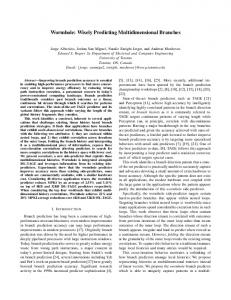
I. I NTRODUCTION Photodynamic therapy (PDT) is an emerging cancer treatment that uses light-sensitive drugs, called photosensitizers, to selectively remove cancerous tumours [3]. Treatment efficacy can be increased by conforming the light dose (photon fluence) contour lines to the shape of the clinical target volume. One of the most flexible, assumption-free, and accurate methods to compute the fluence distribution is the Monte Carlo (MC) method which calculates the fluence based on the simulations of millions of photons. Unfortunately, this method is time-consuming and this problem is compounded because treatment planning for PDT is an iterative process involving multiple parameters. This highlights the need for accelerating the light dose computation to enable the use of MC-based models for clinically robust PDT treatment planning. To explore this possibility, the first goal of this work is to accelerate an MC simulation for PDT based on the widely accepted gold standard software, called Monte Carlo for Multi-Layered media (MCML) [4], on an FPGA. MCML can simulate the propagation of photons through different tissue layers to determine the light dose distribution in the tissue. Fig. 1 depicts an example of a photon simulation using a realistic, five-layer skin model [5]. It shows the paths of
Fig. 1. Photon propagation in a realistic, five-layer skin model using an infinitely narrow beam at 633nm
photon packets within the tissue layers from an infinitely narrow beam irradiating the tissue volume at the skin surface. The second goal of this work is to assist other FPGA developers in accelerating similar computationally intensive applications. Therefore, the development methodology, time required for each stage, techniques to leverage the features of FPGAs, and pitfalls encountered will be presented. The remainder of this paper discusses the FPGA-based hardware design, named here FPGA-based MCML (FBM). This paper first describes MCML and the main computations to be accelerated. Next, the development process for FBM is discussed. The hardware design of FBM and a number of key design decisions are presented in detail. Finally, the validation results and performance of FBM are analyzed based on the five-layer skin model, followed by its implications. II. BACKGROUND A. Related Work Attempts to accelerate MC simulations for modeling light propagation in tissues have been mostly limited to software parallelization schemes. For example, one such scheme involved dividing the simulation into many independent groups, each of which was executed on a different computer or processor in parallel [6], [7]. A problem with this scheme is the need for a large, dedicated network cluster for treatment planning, which tends to consume more power, cost more, and use more space compared to an FPGA board. There has been some prior work on FPGA-based acceleration for related simulations. An MC-based simulation of radiative heat transfer on a Virtex II Pro FPGA achieved a 10.4-fold speedup compared to a 3 GHz workstation
[8]. A convolution-based algorithm used in radiation dose calculations on an FPGA achieved a 20.7-fold speedup [9]. However, they adopted a very different design flow with the use of Handel-C [10]. Also, their speedup values were projected using results from ModelSim because their design was too large to fit on their FPGA. Similarly, [11] presented only a partial implementation of an MC-based computation for radiotherapy without any speedup figures. A working FPGA implementation of MC-based electron transport was shown in [12], reporting speedup between 300 and 500-fold compared to their custom software running on a 64-bit AMD Opteron 2.4 GHz machine. Their work focused on radiation transport computations, which have some similarities to our work, but involve fundamentally different physical interactions, such as electron impact ionization events due to highenergy beams. This work presents a working implementation of the gold standard MC photon migration simulation called MCML (described in the next section) on FPGA hardware. Our work focuses on photon transport for PDT. An earlier paper describing part of this work was published in a biomedical journal, which focuses more on the biomedical aspects of the project and also reports results based on older FPGAs and processors for performance comparison [13].
the photon packet’s mean free path between interaction events. The step size s is calculated using Eq. (1)
B. MCML
The new position for the photon is determined by first multiplying the step size by the direction cosines in the x, y, and z directions (μx , μy , μz respectively) then adding these values to the old position. 3) Direction Update: The direction update step performs two mutually exclusive operations depending on whether or not the photon encounters a boundary during the position update step. If the photon does not encounter a boundary, the scattering angle is computed as follows:
1) Overview: The MCML code [4] provides an MC model of steady-state light transport in multi-layered turbid media. It assumes infinitely wide, planar layers and models an incident pencil beam perpendicular to the surface of the media. The program takes the media properties as inputs and generates a photon distribution in the media as output. Three physical quantities are scored spatially in MCML – absorption, reflectance, and transmittance. For the purposes of PDT treatment planning, only absorption is considered. MCML exploits symmetry of the light source and homogeneity of the individual layers to reduce computation time. In MCML, this means scoring the absorption in 2D (r,z) instead of 3D (x, y, z). Absorption in the tissue is stored in the A[r][z] array, which represents the photon absorption probability density [cm−3 ] normalized to the total number of photon packets launched. If the absorption probability density is divided by the local absorption coefficient, photon fluence [cm−2 ] can be calculated to generate the isofluence lines, which represent regions with equal light dose. These contour lines can be superimposed on top of the corresponding tissue structures to show how close the simulated light dose is to the desired dose in treatment planning. Despite the use of photon packets in MCML, millions of photon packets are required to generate low-noise isofluence maps. Each photon packet undergoes three key steps that are repeated continuously until it is terminated by a survival roulette or by exiting the tissue: position update, direction update, and fluence update. 2) Position Update: The position update step moves the photon packet to its next interaction site by a step size obtained from sampling a probability distribution based on
s=
−ln(ξ) μs + μa
(1)
where ξ is a uniform random variable, μs and μa are scattering and absorption coefficients. This step size may result in the photon packet traversing a boundary. This condition is called a hit and is determined by: � 1 if s - (dl b/μz ) 0 where dl b is the distance to the closest boundary in the direction of photon propagation and μz is the direction cosine (z direction). If the photon packet crosses a boundary, the step size is reduced so that the photon packet arrives at the boundary. The difference between the original step size and the reduced step size is called sleft and is calculated using Eq. (3). sleft is used as the step size for the photon packet’s next iteration. � 0 if hit = 0 (3) sleft = s − (dl b/μz ) if hit = 1
μ�x = μ�y =
sin(θ)[μx μz cos(ψ) − μy sin(ψ)] � + μx cos(θ) 1 − μ2z sin(θ)[μy μz cos(ψ) + μx sin(ψ)] � + μy cos(θ) 1 − μ2z � μ�z = −sin(θ)cos(ψ) 1 − μ2z + μz cos(θ)
(4)
(5) (6)
where (μ�x ,μ�y ,μ�z ) represents the new direction. If the photon encounters a boundary, the direction update step determines whether it reflects or traverses through, and updates the direction accordingly. Whether or not a photon reflects is determined by a series of complex Fresnel calculations explained in detail in [4]. 4) Fluence Update: The fluence update step adjusts the photon packet’s weight to simulate absorption at the site of interaction. The differential weight ΔW to be absorbed is computed based on the current weight W as follows and is accumulated in the absorption array A[r][z] at the location of absorption: ΔW = W
μa μa + μs
(7)
where μa and μs are the optical coefficients of the current layer. 5) Photon Termination: MCML terminates a photon when it exits the tissue or through a survival roulette when the photon weight has reached a predefined threshold value. When the weight reaches the threshold, the survival roulette generates a random number between 0 and 1. If the random number is above 1/10, the photon packet is terminated; otherwise, the weight of the photon packet is increased by a factor of 10 to maintain the conservation of energy in the system. III. D EVELOPMENT OF FPGA- BASED MCML The development process of this work is presented here to assist other developers interested in accelerating similar computationally intensive applications on an FPGA. The development of FBM started with the MCML software and ended with a working design on the DE3 FPGA development board [1]. This mapping from software to hardware required two additional types of specifications: structural and cycle-accurate specifications. The first stage of FBM development was an early architecture exploration of various datapaths to select one that matched well with the resources available on the FPGA chip. The second stage was the modelling of a cycleaccurate pipeline of the architecture selected from the first stage using SystemC [2]. The third stage consisted of a Verilog conversion with precise structural specification to produce a working hardware design. The final stage included optimizations to produce a faster and more accurate design. A. Early Architecture Modeling (2 person-months) This stage focused on understanding the architectural trade-offs available and selecting an appropriate architecture along with the number and type of each core computational unit for that architecture. To facilitate this task, the number of LUTs, registers, multipliers, and memories required for various implementations of each type of computation were measured using empirical experiments. It became clear in this stage that a conversion from floating-point to fixed-point data representation was necessary in order to obtain both good speedup and to accommodate the design on the target FPGA platform. Furthermore, trigonometry and logarithm operations were converted into lookup tables during this stage. The majority of time in early architecture modeling was spent modeling and tuning this fixed-point conversion and lookup tables using an empirical approach to ensure acceptable accuracy was maintained. B. SystemC (5 person-months) SystemC is a design and verification language that consists of a set of C library extensions to model hardware systems at a high level [2]. SystemC was used to add cycleaccurate timing to the untimed early architecture model of the previous stage. This stage consisted of two steps. The first step was to define the inputs and outputs of each core, using a latency of one cycle for simplicity. The second
step involved precisely modeling the latency by defining the pipeline stages. A simple controller was implemented in SystemC to control and test the simulation. C. Hardware (1 person-month) After the completion of the SystemC model of the design, converting the models into Verilog, completing the system controller, and including vendor-specific information were straightforward. The short time required to proceed from the software models in SystemC to a working hardware implementation was surprising. One factor may have been that the precise computation along with values for the inputs, outputs, and key internal signals of each core were already available from the SystemC stage thus speeding up the development, verification, and testing of each core. The end of this development stage resulted in a working implementation of MCML on the Transmogrifier-4 (TM-4) [14]. D. Optimization and Porting (4 person-months) The initial, unoptimized hardware showed an increase in error of 6% in the simulation output when the number of photon packets exceeded the validation test range of the earlier stages of development. To determine the source of error, empirical tests on accuracy were done on the various fixed-point conversions and the random number generator. The most significant source of inaccuracy was the correlation of values produced by the random number generator from [15]. A more rigorous implementation [16] increased the accuracy of the system (1 person-month). Various optimization techniques, such as register-retiming, were applied to improve the clock speed of the design (2 person-months). Once the optimized hardware system was fully validated, the design was migrated from the TM-4 [14] to the DE3 board to provide a more modern comparison than the older Stratix [17] chips on the TM-4 (1 person-month). IV. H ARDWARE D ESIGN A. Modifications from Software Simplifications were made to MCML to meet hardware design requirements and to tailor the solution for PDT treatment planning. First, since fluence is the quantity of interest in PDT treatment planning, only absorption was recorded; the reflectance and transmittance were ignored to reduce the memory resource requirements in hardware. The size of the absorption array was fixed at 256 by 256. Second, the number of allowable layers in the medium was restricted to five to reduce memory requirements. To reduce the area of the design, 64-bit floating-point operations were converted into 32-bit fixed-point operations and lookup tables for trigonometric and logarithmic functions were used. This conversion to fixed-point required the creation of a grid of valid photon positions, as a 32-bit fixed-point number may only take on 232 values. This grid may have a different scale in the r- and z-directions, which can be conceptualized as having different units of measure. Therefore, it was
Stratix III EP3SL150
New photon packet
Direction Update Engine
Position Update Engine
Master Controller
JTAG I/O
Photon Simulator 1. Step Size Core
2.Boundary Checker Core
3. Movement Core
Memories (lookup tables, absorption array)
Top-level system design
necessary to generate the step size in both the r- and zdirections (sr and sz respectively), and conversion between these two is performed using a scaling factor (slef t is handled in a similar fashion). This improves the precision of the simulation space with varying input geometries. B. Implementation 1) Architecture: The hardware design consists of two main components, namely a Master Controller and a Photon Simulator. The Master Controller communicates with the host computer, coordinates access to the memories, and starts and terminates the simulations. The Photon Simulator computes the position and direction of the photon packet, the weight absorbed with the corresponding location of absorption, and determines when to terminate each photon packet. Fig. 2 shows the top-level system design of FBM. The performance-critical portion of the design is the Photon Simulator, due to the low overhead (parsing of input file, system initialization, and data transfer) in this simulation. Two methods for accelerating the problem were considered: maximizing the throughput of a single Photon Simulator through the use of a deep pipeline, or minimizing the size of a Photon Simulator and replicating it to achieve parallelism. It was determined that due to the computationally complex nature of the problem, replicating cores would not efficiently produce speedup. Thus, one high-performance, pipelined Photon Simulator was created. A block diagram of the pipelined Photon Simulator is presented in Fig. 3. The Photon Simulator is aggressively pipelined, leading to a pipeline that is 100 stages deep in total. The pipeline is full at all times except at the beginning and the end of a simulation; however, the time during which the pipeline is not full is less than 0.1% for any simulation with at least 100,000 photon packets. To represent a photon packet, the parameters shown in Table I need to be maintained in every stage of the pipeline. In order to keep track of each photon packet within the pipeline, 357 registers are required, yielding a total of 35,700 registers to maintain photon packet information for all photon packets in the pipeline. This easily fits in the target EP3SL150 FPGA device [18], which contains 113,600 registers, leaving 77,900 for the remainder of the design. 2) Position Update Engine: The Position Update Engine updates the x, y, and z coordinates of a photon packet, and consists of three cores: the Step Size Core, Boundary
4b. Rotation Core
5. Roulette Core
4c. Shared Arithmetic Core
Previous photon packet
Fig. 2.
4a. Reflect Transmit Core
4d.Fluence Update Core
Fig. 3.
Pipelined architecture of Photon Simulator
TABLE I R EGISTERED DATA DESCRIBING A PHOTON PACKET IN A PIPELINE STAGE
Name x coordinate y coordinate z coordinate direction cosine (x) direction cosine (y) direction cosine (z) layer hit boundary? dead? z step size r step size z step size remainder r step size remainder weight
Symbol x-pos y-pos z-pos µx µy µz layer hit dead sz sr sleftz sleftr W
Bit Width 32 32 32 32 32 32 3 1 1 32 32 32 32 32
Checker Core, and the Movement Core. Fig. 4 shows the dataflow diagram for the Position Update Engine. The Step Size Core computes the mean free path (step size) of the photon packet as shown in Eq. (1). The values of sz and sr are assigned through appropriate scaling of this step size. Logarithm tends to be very sensitive to small numbers and very insensitive to large numbers. The following common identity was used to efficiently approximate the logarithm used in Eq. (1) on the FPGA while retaining its sensitivity property: ln(ξ) = log2 (ξ)/ log2 (e) = log2 (xm ∗ 2xe )/ log2 (e) = (xe + log2 (xm ))/ log2 (e)
(8)
where xe is the base-2 exponent of ξ and xm is the base-2 significand of ξ. ξ is a uniformly distributed random variable with a range from 0 to 1 and is implemented using [16]. xe is determined using a priority encoder on ξ because its value is equivalent to the position of the most significant 1 bit in ξ. log2 (xm ) is implemented using a 10-bit lookup table on the 10 trailing bits from the most significant 1 bit in ξ. Division by the constant log2 (e) is implemented by a multiplication of its reciprocal. Once the step size is known, the Boundary Checker Core determines whether or not the photon packet will hit
Random Number Generator
R, Z-direction constants
Logarithm
Step Size Core (1 stage)
5:1 5:1 Next layer Previous layer z-pos z-pos
XX
z-pos
z-pos
−
−
sleftr, sleftz
sr, sz sleftz = 0?
2:1 5:1 sz
2:1 ȝz
scaling constant
sr sz sr,
/
X hit
2:1 5:1 sr, sz
sz > dl_b
dl_b
Boundary Checker Core (60 stages)
ȝx, ȝy, ȝz
XX X
ȝz < 0?
Movement Core (1 stage) x-pos, y-pos, z-pos
++ + x-pos, y-pos, z-pos
Fig. 4. Detailed data-flow diagram for the Position Update Engine, where dl b represents the distance to the closest boundary in the direction of photon propagation. Overlapped shapes represent identical datapaths for a group of signals.
a boundary using Eq. (2) and determine the step size remainder using Eq. (3). Similar to the step size, slef tz and slef tr are assigned an appropriately scaled value of slef t. The Boundary Checker Core contains a total of 60 pipeline stages. Thirty two of these stages come from the pipelined computation of a division (30 stages), followed by the computation of two multiplications (1 stage each). As the critical path was found to be within the Boundary Checker Core, an additional 28 pipeline stages were added to the end of the Boundary Checker Core to allow Quartus II to automatically perform register retiming. Finally, the Movement Core computes the new values of the x, y, and z positions based on the results of the previous two cores. This phase involves a multiplication of the appropriate step size by the direction cosines in the x, y, and z directions respectively (μx , μy , μz ). These values are then added to the previous values for the position vector. 3) Direction Update Engine: The Direction Update Engine changes the direction cosines (μx , μy , and μz ), and consists of three cores: the Reflect-Transmit Core, the Rotation Core, and the Shared Arithmetic Core. Each time a photon packet proceeds through its main loop, it will either encounter a boundary, or it will interact with the medium, but it will never do both in a single iteration. This behaviour allows the sharing of resources. Any access to a shared arithmetic unit is passed through a MUX, which
significantly reduces the number of arithmetic units required by the design. The Rotation Core uses equations (4), (5), and (6) to calculate the new direction of a photon packet when it does not hit a boundary. The hardware design used to calculate these values is shown in Fig. 5a. To avoid trigonometry in hardware, lookup tables are used to generate sin(θ), cos(θ), sin(ψ), and cos(ψ). The pipeline for the Rotation Core was optimized to reduce the number of registers and arithmetic units (multipliers, dividers, and square root units) used. One optimization technique used was common subexpression elimination: calculating a result once and reusing it in multiple calculations. A second technique employed was to share arithmetic units with the Transmit-Reflect Core. As shown by the shaded blocks in Fig. 5, each of the shared arithmetic units in the Reflect-Transmit Core (Fig. 5b) is matched in the same stage by the same unit in the Rotation Core (Fig. 5a). Finally, by calculating results as late as possible (without increasing total latency) the number of registers required to propagate intermediate results was minimized. The Reflect-Transmit Core determines the direction a photon packet will travel upon reaching a boundary. It further determines whether or not the photon packet will transmit into the next layer (Fig. 6). The calculation of the Fresnel formulas are resource intensive, but not critical for precision, and thus is implemented as lookup tables. If the photon packet reflects, and hence remains in the current layer, μz is negated and all other photon packet parameters remain the same. Should the photon packet traverse through, the calculation shown in Fig. 5b) is used to determine the new direction vector. In this case, the layer value is also updated, and the dead flag is set if the photon packet exits the tissue into air. 4) Fluence Update Core: The Fluence Update Core updates the weight of each photon packet and adjusts the values stored in the absorption array. The maximum size of the simulation region was fixed to be 256 × 256 elements in the r and z dimension (radial symmetry is assumed in this model) due to the use of on-chip memory for storing the absorption array. The resolution (dr and dz) can be adjusted in the simulation input file. However, by fixing the grid dimensions at 256 × 256 elements, two divisions were turned into bit-shift operations, decreasing the depth of the pipeline, and saving area. The width of the data stored in the absorption array was set to 62 bits to both avoid overflow as well as fit on the Stratix III chip. Note that this is sufficient to accept the total weight of 100 million photon packets deposited on a single array element. One point of complexity in the Fluence Update Core involved a potential Read After Write (RAW) hazard. There is a two clock cycle delay between writing a value into the on-chip memory and that value being available for reading. Thus, to ensure that the latest value is always read, each photon packet checks to see if the next two photon packets map to the same location in the absorption array. If a match is found, the photon packet forwards the value that will be
b) Reflect-Transmit Core
a) Rotation Core μz 264 - 1
μz
μz 64 layer constants 2 - 1
X
−
μx
264 - 1
X
X
Stage 1
−
5:1
μz
μz
Stage 2
X
Stage 3
− √⁻
√⁻
264 - 1
Stage 4
/
Stage 5
...
new μz RNG
μy
cosp LUT
μz
X
X
X
− new μz
sinp LUT
sint LUT
cost LUT
X
− X
μx
+
new μy
new μx
Stage 31 μx
μy
X
Stage 32 layer constants
X
X
+
Stage 30
μy
X
X
−
...
RNG
X X
Stage 15
layer constants
Stage33 μz
X
5:1
5:1
μx μy
X
X
Stage 34
Stage 35 Stage 36
new μx
new μy
Fig. 5. Dataflow diagram for a) the Rotation Core, and b) the Reflect-Transmit Core. Results computed from the Reflect-Transmit core are used when a photon packet hits a boundary. Otherwise, the results from the Rotation Core are used. Shaded blocks indicate shared arithmetic units. μz
μz
Up Fresnel LUT μz > 0
Down Fresnel LUT 2:1 rfres
RNG
rnd
rnd < rfres
reflected transmitted 2:1
Fig. 6. Reflect-Transmit Core logic to determine whether a photon packet transmits or reflects
written back to the memory, as opposed to using the value read from memory. 5) Roulette Core: The Roulette Core determines when to discontinue simulating a photon packet when the photon packet has not yet exited the tissue, but has dropped below the threshold weight. When a photon packet’s weight drops below the threshold weight, a random number (between 0
and 1) is generated in the Roulette Core. If the random number is above 1/8, the photon packet is terminated. If it is below 1/8, the weight of the photon packet is increased by a factor of 8 to maintain conservation of energy in the system. Note that a power of 2 was used instead of the number 10 used in the software MCML for hardware efficiency, while maintaining simulation accuracy. V. E XPERIMENTS AND R ESULTS The design presented in this paper was first implemented on a multi-FPGA platform called the Transmogrifier-4 (TM4) [14] and then migrated to the DE3 board, which has one Stratix III (EP3SL150F1152C3) FPGA [18]. This section only presents results from the DE3 platform. For the purpose of validation and performance comparison, a realistic skin model [5] was selected as the simulation input to the MCML program. A. Validation System validation consisted of two phases. The first phase involved verifying the FBM simulation outputs against the
TABLE II P OWER -D ELAY P RODUCT OF S TRATIX III VS 3 GH Z X EON FOR MCML SIMULATION WITH 100 MILLION PHOTON PACKETS
18% 16%
Relative Error
14%
Machine Single-core Xeon Stratix III
12% 10%
Power 40 W 1.55 W
PDP 244 kJ 0.341 kJ
Normalized PDP 716 1
8% 6% 4% 2% 0% 1.0E+05
1.0E+06
1.0E+07
1.0E+08
Number of Photons MCML run 1 vs MCML run 2
FBM vs. MCML
Fig. 7. Relative error as a function of the number of photon packets simulated. The horizontal axis is in logarithmic scale.
gold standard MCML executed on an Intel Xeon processor. Due to the pseudo-random nature of MC algorithms, it is important to separate the error introduced by the hardware implementation (including lookup tables and fixed-point conversion) from the statistical uncertainty inherent in an MC simulation. In other words, a fair comparison between MCML and FBM can only be obtained by considering the variance in the output of the MCML simulation, which is a 2D absorption array scoring the photon probability density [cm−3 ] as a function of radius and depth. To quantify differences between these arrays, the relative error E[r][z] between corresponding elements was computed using Eq. (9): E[r][z] =
|As [r][z] − Ah [r][z]| As [r][z]
(9)
where As is the gold standard absorption array produced by MCML after launching 100 million photon packets and Ah contains the corresponding elements in the absorption array produced by FBM. To summarize the effect of varying the number of photon packets, the mean relative error is shown in Fig. 7, averaging the relative error over all absorption array elements (256 × 256) with values above a threshold of 0.00001 cm−3 . The threshold is necessary since the relative error is undefined when As [r][z] is zero. Photon packet numbers ranging from 105 to 108 were simulated. The second phase for system-level validation of the FPGA-based hardware design involved analyzing the error in the context of PDT treatment planning. Isofluence maps were generated from the FBM output based on 108 photon packets, as illustrated in Fig. 8. The relative shift in the position of the isofluence lines was 0.1 mm in the hardwaregenerated isofluence lines compared to those produced by MCML for fluence levels as low as 0.00001 cm−2 . This shift is negligible within the context of PDT treatment planning considering the typically much larger margin of safety for surgical resection or treatment planning in radiation therapy.
B. Area and Speedup FBM on the Stratix III used 31,185 out of 56,800 ALMs (Stratix III soft logic blocks), 92 out of 384 DSP blocks, and 4,751,360 out of 5,630,976 block memory bits. FBM on the Stratix III clocked at 80 MHz achieved a 28fold speedup compared to a single-core 3 GHz Xeon 5160 processor with 8 GB of RAM and 4 MB of cache. The onchip simulation time was 6102 seconds for the processor and 220 seconds for the FPGA. A third-party host-to-FPGA communication core that is still under development was used to port the TM-4 design over to the DE3. This core has a performance problem and requires over three hours to transfer one megabyte of data. The total amount of data that needs to be transferred to and from the device is less than a megabyte and should take less than one second given a welldesigned host interface. For this reason, the data-transfer overhead was not included in the reported simulation time. C. Power Comparison Power consumption is another metric to compare computational efficiency between the FPGA and the processor. Only the power consumed by the processor or FPGA was considered; off-chip memory, network, and disk power were ignored. The thermal design power of the dual core Xeon 5160 processor [19] is specified by Intel to be 80W, and we use half of this value as the power consumption for a single core. Although 40 W may be pessimistic for the single core, this value was chosen because the processor will be heavily utilized during the computation in MCML. The FPGA power consumption was determined using the PowerPlay Power Analyzer tool in Quartus II version 8.1 [20]. The default settings for PowerPlay were used. Input pin toggle rate was left at the default 12.5% to approximate the power consumption of the FPGA. Note that although most of the inputs remain almost constant during the simulation of any large number of photon packets, the default settings were chosen to give a more conservative estimate. Also, since the host processor can perform other tasks while waiting for the simulation on the FPGA to complete, its power was not included in the power calculation for the FPGA. Table II shows that FBM on the Stratix III has a 716-fold better power-delay product than a single-core 3 GHz Xeon 5160 processor. Also, under these assumptions, a hypothetical cluster of processors that matches the FPGA speedup will still have the same 716-fold worse power-delay product compared to the FPGA. VI. C ONCLUSIONS AND F UTURE W ORK Using the MCML program as the gold standard, custom pipelined hardware was designed on the DE3 board to
(a)
0.04 0.06
0.02
0.04
0.06
0.08
0.10
0.12
1000 100
0.08 0.10
10
0.12 0.14 0.16
Depth (cm)
0.02
Depth (cm)
(b)
Radius (cm) 0.00 0.00
Radius (cm) 0.00 0.00 0.02 0.04 0.06 0.08 0.10 0.12 0.14 0.16 0.18 0.20
0.20
1
0.40
0.01
0.60
0.80
1e-5
Fig. 8. Comparison of the isofluence lines generated by FBM and MCML using 100 million photon packets. Fluence levels range from 1000 cm−2 to 0.00001 cm−2 as indicated in parts (a) and (b) of the figure. �, ♦, and �: MCML; •, +, and ×: FBM
achieve a 28-fold speedup and a 716-fold lower powerdelay product compared to a 3 GHz Intel Xeon processor. The development time was approximately 1 person-year. Isofluence distribution maps generated by FBM and MCML were compared at 100 million photon packets, showing only a 0.1 mm shift in the hardware-generated isofluence lines from those produced by MCML for fluence levels as low as 0.00001 cm−2 . This shift is negligible within the context of PDT treatment planning. The implications of the current study are twofold. First, the pipelined design could form the basis on which more complex MC simulations can be built. Secondly, the dramatic reduction in treatment planning time enables realtime treatment planning based on the most recent images of the clinical target volume, taking into account the changing tissue optical properties as the treatment progresses. Currently, pre-treatment models assume constant values for tissue optical properties and ignore the dynamic nature of tissues, which could directly affect treatment outcomes in interstitial PDT [21]. The significant performance gain provided by the hardware approach allows PDT treatment planning in heterogeneous, spatially complex tissues using more sophisticated MC-based models. ACKNOWLEDGEMENTS The authors acknowledge David Galloway’s support with JTAG ports package for the DE3 [1], the financial support from CIHR (Grant No. 68951), NSERC (Discovery Grant No. 171074) and the NSERC and OGS scholarships. R EFERENCES [1] Terasic Technologies, “Altera DE3 Development and Education Board user handbook,” Nov 2008, dE3 http://www.terasic.com.tw/ attachment/archive/260/DE3 User manual v1.2.pdf. [2] T. Grtker, S. Liao, G. Martin, and S. Swan, System Design with SystemC. Springer, 2002. [3] T. Dougherty, “Photodynamic Therapy,” Photochemistry and Photobiology, vol. 58, no. 6, pp. 895–900, 1993. [4] L. Wang, S. Jacques, and L. Zheng, “MCML-Monte Carlo modeling of light transport in multi-layered tissues,” Computer Methods and Programs in Biomedicine, vol. 47, no. 2, pp. 131–146, 1995. [5] V. Tuchin, “Light scattering study of tissues,” Physics-Uspekhi, vol. 40, no. 5, pp. 495–515, 1997.
[6] A. Colasanti, G. Guida, A. Kisslinger, R. Liuzzi, M. Quarto, P. Riccio, R. G., and F. Villani, “Multiple Processor Version of a Monte Carlo Code for Photon Transport in Turbid Media,” Computer Physics Communications, vol. 132, pp. 84–93, 2000. [7] S. Coyle, K. Thomas, T. Naughton, M. Charles, and W. Toms, “Distributed Monte Carlo Simulation of Light Transportation in Tissue,” in Parallel and Distributed Processing Symposium, 2006. Proceedings. 20th IEEE International Symposium on, 2006, p. 4. [8] M. Gokhale, J. Frigo, C. Ahrens, J. Tripp, and R. Minnich, “Monte Carlo Radiative Heat Transfer Simulation on a Reconfigurable Computer,” Lecture notes in computer science, pp. 95–104, 2004. [9] K. Whitton, X. Hu, Y. Cedric, and D. Chen, “An FPGA Solution for Radiation Dose Calculation,” in Field-Programmable Custom Computing Machines, 2006. Proceedings. 14th Annual IEEE Symposium on, 2006, pp. 227–236. [10] Agility, “Handel-c language reference manual,” 2007, http://www. agilityds.com/literature/HandelC Language Reference Manual.pdf. [11] V. Fanti, R. Marzeddu, C. Pili, P. Randaccio, and J. Spiga, “Monte Carlo Computations for Radiotherapy with the use of Dedicated Processors,” in Nuclear Science Symposium Conference Record, 2006. IEEE, vol. 4, 2006. [12] A. S. Pasciak and J. R. Ford, “High-speed Evaluation of Trackstructure Monte Carlo Electron Transport Simulations,” Physics in Medicine and Biology, vol. 19, no. 53, pp. 5539–5553, 2008. [13] W. Lo, K. Redmond, J. Luu, P. Chow, J. Rose, and L. Lilge, “Hardware Acceleration of a Monte Carlo Simulation for Photodynamic Therapy Treatment Planning,” Journal of Biomedical Optics, vol. 14, p. 014019, 2009. [14] J. Fender, J. Rose, and D. Galloway, “The transmogrifier-4: an FPGAbased hardware development system with multi-gigabyte memory capacity and high host and memory bandwidth,” in Field-Programmable Technology, 2005. Proceedings. 2005 IEEE International Conference on, 2005, pp. 301–302. [15] Thomas Tkacik, “A hardware random number generator,” Aug 2002, open Core Design from Motorola Incorporated http://www.opencores. org/projects.cgi/web/systemc rng/overview. [16] P. L’Ecuyer, “Maximally Equidistributed Combined Tausworthe Generators,” Mathematics Of Computation, vol. 65, no. 213, pp. 203–213, 1996. [17] Altera Corporation, “Stratix device handbook,” Jan 2006, stratix http: //www.altera.com/literature/hb/stx/stratix handbook.pdf. [18] Altera Corporation, “StratixIII device handbook,” Nov 2007, stratix 3 http://www.altera.com/literature/hb/stx3/stratix3 handbook.pdf. [19] Intel Corporation, “Dual-core intel xeon processor 5160 (4m cache, 3.00 ghz, 1333 mhz fsb),” Dec 2008, xeon 5160 Data Sheet http: //ark.intel.com/cpu.aspx?groupId=27219. [20] Altera Corporation, “Quartus ii 8.1: Powerplay power analysis,” Nov 2008, quartus II Introduction http://www.altera.com/literature/hb/qts/ qts qii53013.pdf. [21] A. Johansson, N. Bendsoe, K. Svanberg, S. Svanberg, and S. Andersson-Engels, “Influence of treatment-induced changes in tissue absorption on treatment volume during interstitial photodynamic therapy,” Medical Laser Application, vol. 21, no. 4, pp. 261–270, 2006.