Virtex-II Pro development board and Xilinx System Generator. (XSG). The proposed ... in many areas such as audio and video, signal processing, automotive ... increase the operating frequency and compensate the imposed delays. II.
FPGA-Implementation of a Sequential Adaptive Noise Canceller using Xilinx System Generator Mohammed Bahoura
Hassan Ezzaidi
Department of Engineering, University of Quebec at Rimouski, 300, all´ee des Ursulines, Rimouski, Que., Canada
Department of Applied Sciences, University of Quebec at Chicoutimi, 550, boul. de l’Universit´e, Chicoutimi, Que., Canada,
Abstract— This paper presents a sequential architecture of a pipelined LMS-based adaptive noise cancellation to remove the power-line interference (50/60 Hz) from electrocardiogram (ECG). This architecture is implemented on on FPGA using XUP Virtex-II Pro development board and Xilinx System Generator (XSG). The proposed architecture was evaluated using real ECG signals from the MIT-BIH database. Hardware requirement of this adaptive noise canceller is presented for various filter lengths.
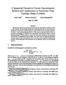
II. A DAPTIVE N OISE C ANCELLATION Adaptive noise canceller is an interesting application of adaptive filter that has been used in a wide range of applications [4]. Figure 1 shows a block diagram of an adaptive noise canceller which consists of two inputs signals and an adaptive filter. A. Least mean square (LMS)
I. I NTRODUCTION Field programmable gate arrays (FPGAs) are widely used in many areas such as audio and video, signal processing, automotive electronic, digital communication systems, etc. Because of their high performance and flexibility, FPGAs are gradually replacing ASICs and DSPs in many application fields. One of the advantages of FPAGs-based embedded systems is their ability to integrate customized user cores with a soft or hard embedded processor in system-on-a-chip (SoC) solutions [1]. However, programming FPGAs using Hardware Description Languages (HDL) is too time consuming and needs background in a chip design. This situation has been changing over the last decade with the emergence of a new class of high-level programming tools and languages for FPGA design: Handel-C, AccelDSP, Xilinx System Generator for DSP, etc. Xilinx System Generator (XSG) [2] is high-level software tool that enables the use of MATLAB/Simulink environment to create and verify hardware designs for Xilinx FPGAs quickly and easily. It provides a library of Simulink blocks bit and cycle accurate modeling for arithmetic and logic functions, memories, and DSP functions. It also includes a code generator that automatically generates HDL code from the created model. Generated HDL code can be synthesized and implemented in the Xilinx FPGAs. The XSG blocks are like standard Simulink blocks except that they can operate only in discrete-time and fixed-point format. In this work, an adaptive noise canceller to remove powerline interference from ECG signal is implemented on FPGA using XSG tool. The proposed architecture extends the principle used in the sequential FIR filter schema [3] to include the LMS algorithm. The fully-pipelined architecture permits to increase the operating frequency and compensate the imposed delays.
The least mean square (LMS) is the most used algorithm to iteratively minimizing the mean square error (MSE) of the system output. For an M -th order adaptive filter, the LMS algorithm can be expressed as: ek = d k − yk
yk =
N −1 X
wi,k xk−j
(1)
(2)
j=0
Wk+1 = Wk + 2µek Xk
(3)
where Wk = [w0,k , w1,k , . . . , wN −1,k ]T is the filter coefficients at time n, Xk = [xk , xk−1 , . . . , xk−N +1 ]T are the last N sample the reference input at time n, and µ is a positive parameter controlling the stability and the convergence speed. A larger value for µ can increase the convergence speed, but smaller value can assure better stability. B. Delayed least mean square (DLMS) In some practical applications the LMS algorithm can be implemented only with delayed coefficient adaptation [5]. As shown in Fig. 2, the so-called delayed least mean square (DLMS) algorithm can be obtained by inserting the delay (z −m ) into the error feedback loop of the LMS algorithm [6], [7]. The DLMS algorithm is then expressed by the following equations [5]: yk =
N −1 X
wi,k xk−i
(4)
i=0
ek−m = dk−m − yk−m
(5)
Wk+1 = Wk + 2µek−m Xk−m
(6)
Fig. 1.
Adaptive noise canceller block diagram.
Fig. 3.
Sequential LMS-based adaptive noise canceller.
Fig. 2. Bloc diagram of DLMS algorithm, where m is the number of the unit delays.
where m is the number of the unit delays. It is shown that the delay in the coefficient adaptation has only a minor effect on the steady-state behavior if the step size is within certain bonds [5], [8]. The major penalities with the DLMS algorithm are a reduced convergence speed for stationary signals and a poorer tracking capability for nonstationary signals [5], [8].
Fig. 4.
Sequential delayed LMS-based adaptive noise canceller (m = 3).
III. S EQUENTIAL A RCHITECTURE The FIR filters can be implemented by several different architectures: sequential, parallel and semi-parallel. The type of architecture chosen is typically determined by the amount of the required processing [3]. The two most important factor are: • Sample rate • Number of Coefficients The parallel architecture is well suited for a high sampling rate requirements and a small number of coefficients. However, the sequential architecture is more suited for a low sampling rate requirements and a large number of coefficients. The semiparallel architecture is a good compromise that permits to implement filters having a large number of coefficients and requiring a high sampling rate. In this paper, a sequential architecture of the LMS-based adaptive FIR filter is proposed and implemented on FPGA. As shown in Fig. 3, the input data xk and error ek are upsampled to allow the sequential computation of the filter output yk , which is obtained by down-sampling. The input data and filter coefficients are stored using a dual-port block RAM. The memory addresses are clocked M time faster than the input samples, where M is the number of filter taps. Both RAMs are configured in read after write. At each address clock, one filter coefficient is updated using the LMS algorithm before that is multiplied with the corresponding data and added to the accumulator content. After M address clocks a new input sample is stored in the data RAM and the accumulator is
Fig. 5.
Sequential pipelined LMS-based adaptive noise canceller.
re-initialized. More detail on the FIR filter implementation can be found in [3]. Our contribution consists to update the filter coefficients sequentially according to the LMS algorithm. However, the direct implementation of the circuit of Fig. 3 cannot be recommended because components such as block RAM, accumulator and the down-sampler include delays that can affect the filter output quality. This problem can be solved by inserting an appropriate number of delays (m = 3) to compensate the previously listed delays (Fig. 4). The fullypipelined circuit (Fig. 5) is obtained by retiming the inserted delay that permits to increase the operating frequency by minimizing the critical path [5], [7], [8]. It can be noted that one delay (z −1 ) of the original signal is equivalent to M delays (z −M ) of the up-sampled signal.
Fig. 6. Top-level Simulink design diagram of an adaptive noise canceller using Xilinx System Generator is given on the top and detailed sequential architecture of a pipelined LMS-based adaptive noise canceller sub-system is presented on the bottom.
IV. FPGA I MPLEMENTATION Fig. 6 presents a sequential architecture of a pipelined LMSbased adaptive noise canceller used to remove power-line interference from ECG signals. As labeled on the connecting wires (FIX 16 14), the fixe-point data is a 2’s complement signed 16-bit number having 14 fractional bits. Xilinx University Program Virtex-II Pro Development System [9] is used to implement this adaptive noise canceller. After successful simulation, the hardware co-simulation compilation automatically creates bitstream file and associates it with a JTAG co-simulation block. Table I gives in details the ressource requirement of the FPGA implementation as reported by the Xilinx ISE Foundation. The filter length is mainly limited by the number of multipliers available on the FPGA. Table II shows the maximum operating frequency, which is approximately constant for various filter lengths. There is no combinational path because the system is fullypipelined. It should be noted that it is very easy to migrate this architecture on the more recent Xilinx FPGA devices.
V. E XPERIMENTS AND R ESULTS A. Database We used the MIT-BIH arrhythmia database [10] to evaluate the performance of the proposed hardware implementation of the adaptive noise cancellation system. This database contains 48 half-hour excerpts of two-channel ambulatory ECG recordings, which were obtained from 47 subjects. The recordings were digitized at 360 samples per second per channel with 11-bit resolution over a 10 mV range. B. Results The hardware-in-the-loop co-simulation permits to incorporate design running in an FPGA directly into a Simulink simulation (Fig. 7). When the design is simulated, the compiled portion (JTAG co-simulation block) is actually running on the hardware and data is transferred between computer and FPGA board. Fig. 8 shows the adaptive noise cancelation results obtained with real ECG signal which is contaminated with 60 Hz
TABLE I R ESSOURCE UTILIZATION FOR CONVENTIONAL AND PIPELINED ARCHITECTURES . AVAILABILITY OF X ILINX V IRTEX -II P RO XC2VP30 FPGA ARE GIVEN BETWEEN BRACKETS . Filter length Slices (13,696) Flip-flops (27,392) 4-LUTs (27,392) Block RAMs (136) 18-bit MULT (136) GClocks (16) Ext IOBs (556) Equivalent gates
4 155 236 187 1 2 1 49 79,272
8 174 271 222 1 2 1 49 81,633
16 183 290 243 1 2 1 49 82,848
32 233 389 343 1 2 1 49 89,826
64 330 584 540 1 2 1 49 103,710
128 523 971 911 1 2 1 49 130,394
256 870 1662 1619 1 2 1 49 181,020
512 1591 3105 3062 1 2 1 49 284,754
1024 3047 6020 5979 1 2 1 49 560,014
TABLE II M AXIMUM OPERATING FREQUENCY AND COMBINATIONAL PATH DELAY FOR CONVENTIONAL AND PIPELINED ARCHITECTURES . Filter length Maximum operating frequency (MHz) Maximum combinational path delay (ns)
4 162.985 -
8 162.985 -
16 162.985 -
interference signal. This figure includes the clean ECG signal (top), the primary input that is composed of ECG and the 60 Hz signal (middle) and the the output of the adaptive canceller (bottom), where the interference signal is eliminated once the adaptive process has converged.
32 162.985 -
64 162.985 -
128 162.985 -
256 162.985 -
512 162.985 -
1024 162.985 -
VI. C ONCLUSION In this paper, a sequential architecture of a pipelined LMSbased adaptive noise canceller to remove power-line interference from ECG signal is implemented on FPGA using Xilinx System Generator. Successful results are obtained with various filter lengths. VII. ACKNOWLEDGEMENTS The author would like to thanks Xilinx for the provided software and hardware under the University program donation. R EFERENCES
Fig. 7. Hardware-in-the-loop co-simulation of the adaptive power-line interference cancelation from ECG signal.
Fig. 8. Illustrative example of the power-line suppression with the first 12s of the MIT-BIH ECG tape 202 record. a) Original ECG signal x[k], b) Primary corrupted input d[k], c) Filtered signal e[k].
[1] A. Vera, U. Meyer-Baese, and M. Pattichis, “An fpga based rapid prototyping platform for wavelet coprocessors,” in Proceedings of SPIE - The International Society for Optical Engineering, vol. 6576, 2007. [2] “Xilinx System Generator for DSP,” www.xilinx.com/ise/optional prod/system generator.htm, Xilinx. [3] DSP: Designing for Optimal Results, 1st ed., ser. Advanced Design Guide. Xilinx Inc, 2005. [4] B. Widrow, J. R. G. Jr, and J. M. McCool, “Adaptive noise cancelling: principles and applications,” Proceedings of the IEEE, vol. 63, no. 12, pp. 1692–1716, 1975. [5] G. Long, F. Ling, and J. Proakis, “Lms algorithm with delayed coefficient adaptation,” IEEE Trans. Acoust. Speech, Signal Processing, vol. 37, no. 9, pp. 1397–1405, 1989. [6] T. Kimijima, K. Nishikawa, and H. Kiya, “An effective architecture of the pipelined LMS adaptive filters,” IEICE Trans. Fundamentals, vol. E82-A, no. 8, pp. 1428–1434, 1999. [7] K. Matsubara, K. Nishikawa, and H. Kiya, “Pipelined adaptive filters based on look-ahead-based delayed LMS algorithm,” Electronics and Communications in Japan (Part II: Electronics), vol. 82, no. 1, pp. 55– 62, 1999. [8] Y. Yi, R. Woods, L. K. Ting, and C. F. N. Cowan, “High speed fpgabased implementations of delayed-lms filters,” Journal of VLSI Signal Processing Systems for Signal, Image, and Video Technology, vol. 39, no. 1-2, pp. 113–131, 2005. [9] “Xilinx University Program Virtex-II Pro Development System,” www.xilinx.com/products/devkits/XUPV2P.htm, Digilent Inc. [10] A. L. Goldberger, L. A. N. Amaral, L. Glass, J. M. Hausdorff, P. C. Ivanov, R. G. Mark, J. E. Mietus, G. B. Moody, C.-K. Peng, and H. E. Stanley, “PhysioBank, PhysioToolkit, and PhysioNet: Components of a new research resource for complex physiologic signals,” Circulation, vol. 101, no. 23, pp. e215–e220, 2000 (June 13).