FPGA Implementation of Autonomous Navigation Algorithm with Dynamic Adaptation of Quality of Service Jos´e Carlos S´a Faculdade de Engenharia Universidade do Porto
[email protected]
Jo˜ao Canas Ferreira INESC TEC and Faculdade de Engenharia Universidade do Porto
[email protected]
Abstract
are described in Sect. 5, while Sect. 6 discusses the results. Section 7 concludes the paper.
The main goal of this work is to build an hardwareaided autonomous navigation system based on real-time stereo images and to study Partial Reconfiguration aspects applied to the system. The system is built on an reconfigurable embedded development platform consisting of an IBM PowerPC 440 processor embedded in a Xilinx Virtex5 FPGA to accelerate the most critical task. Three Reconfigurable Units were incorporated in the designed system architecture. The dynamic adjustment of system’s quality of service was achieved by using different reconfiguration strategies to match vehicle speed. A speedup of 2 times for the critical task was obtained, compared with a softwareonly version. For larger images, the same implementation would achieve an estimated speedup of 2.5 times.
1. Introduction The performance expected from complex real-time embedded systems has been increasing more and more. The application presented in this work is a good example of such a system. It uses a complex autonomous navigation algorithm for guiding a small robot using information obtained from a pair of cameras. Since the computational effort is significant for an embedded system, a previous software/hardware partitioning step identified the critical task and proposed its implementation in hardware. Modern platform FPGAs like the Virtex-5 (from Xilinx) can combine the flexibility of software running on an embedded processor (a PowerPC processor in this case) with the performance of dedicated hardware support. The main objectives of the work described here are to evaluate the application of dynamic partial reconfiguration (DPR) [1] by designing and building and assessing a prototype. This subject is one of the case studies proposed by the European consortium REFLECT project, which also provided the original application software written in C language. The paper is organized as follows: Section 2 briefly provides some background information, while Sect. 3 gives an overview on the application under study. Section 4 describes the structure of the critical task to be accelerated. The system and strategies used for the evaluation of DPR
ISBN: 978-972-8822-27-9
Jos´e Carlos Alves INESC TEC and Faculdade de Engenharia Universidade do Porto
[email protected]
2. Background Reconfigurable systems combine two main key concepts in embedded technology: Parallelism, which is the biggest advantage of hardware computing, as provided by Application-Specific Integrated Circuits (ASICs), and flexibility, the main reason for the success of software applications run by General Propose Processors (GPPs). The concept of reconfigurable system is breaking the barrier between these two types of devices. This allowed the combination of the particularities of both and elevate the concept of embedded system to a new level, creating new types of compromise between the software and the hardware infrastructure. A reconfigurable embedded system allows portions of the system’s hardware to be modified, thereby changing system’s hardware-accelerated features depending on the need of the application executed by the GPP. This feature offers a new degree of flexibility to the embedded system, where the execution of more tasks in hardware provides a multi-level acceleration that is difficult to obtain by a fixed-functionality circuit. The state of the art reconfiguration technology, the Dynamic Partial Reconfiguration, allows FPGA regions to be changed at run-time, without interrupting the GPP, or rest of the hardware execution. Fig. 1 shows an example of a partial reconfiguration system, where the hardware part of the system is composed of four modules that execute HWaccelerated tasks. In this example, two of them are remain fixed, executing functions that requires permanent availability, whereas the remaining blocks are reconfigurable modules. For the example, function C can the exchanged with function D, since the have been designed to use the same reconfigurable region; the same applies to functions E and F, but for a different reconfigurable region. The compliance with this technology has some costs. For instance, the design flow for reconfigurable systems followed by the Xilinx EDK1 [2] requires some effort to design compatible interfaces between reconfigurable modules for a particular region. The major drawback of dynamic reconfiguration is the
REC 2013
1 EDK
- Embedded Development Kit.
111
Reconfigurable Function D
Horizontal Filter
Reconfigurable Function F
3x3 Reconfigurable Function C
GPP
Reconfigurable Function E
1
Hardware Fixed Function A
Fixed Function B
( )²
x
( )²
7
2 Vertical ConvRepl1 Filter 1x11
ConvRepl1
3
8 ConvRepl2
5
ConvRepl1
6 ConvRepl2
ConvRepl2
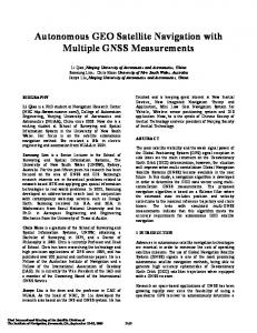
Figure 2. Operation Flow for Harris Corner Detector Algorithm 3D Reprojection Analytically calculates the threedimensional coordinates of a point from twodimensional images. Robust pose estimation - Runs the RANSAC algorithm [6] to separate relevant inlier image features from outliers. In each loop iteration a Singular Vector Decomposition (SVD) algorithm computes a vehicle rotation matrix and a translation vector.
4. Critical Task: Feature Extraction
The Stereo Navigation application used in this work supports localization mechanisms like Global Navigation Satellite Systems (GNSS) in vehicles where this service is temporarily unavailable. Two cameras pointed in the same direction capture the scenery ahead of the vehicle at the same instant, forming a stereo image. From the processing of stereo images in consecutive instants, the embedded system can determine vehicle rotation and translation matrices. The main loop of the Stereo Navigation algorithm comprises the following steps: Image rectification Eliminates image distortions caused by the lens surface. Feature extraction Detects characteristics of a given image using the Harris Corner Detector algorithm [5]. Feature matching Searches correspondences between the features of the stereo image belonging to consecutive instants.
From the analysis of the run-time behavior of the application, combined with the information provided in previous works [7, 8], it follows that feature extraction is the most time consuming processing task. This task is responsible for detecting relevant image features using the Harris Corner Detector algorithm and is executed once for each 96 × 96 pixel block of both left and right images. Twelve blocks are processed per image, 24 for the stereo image.
4.1. Computation Flow As shown in Fig. 2, each execution of the algorithm comprises eight 2-D convolution operations: 2 × ConvConst, 3 × ConvRepl1 and 3 × ConvRepl2. All the convolution operations are based on Eq. 1, where the result of multiply-accumulate (MAC) operations between matrix filter h (size 3×3) and each input element present in array u (of size 96×96) is stored in the output matrix y (also of size 96×96).
2 Bitstream - Stream of data containing information of FPGA internal logic cells end routing configuration.
112
ConvConst
1x11
Figure 1. Dynamic Partial Reconfiguration System.
3. Embedded Application
3x3 4
ConvConst
Horizontal Filter
reconfiguration time, which directly depends on partial bitstream2 data transfer time. Since the bitstream size is proportional to the FPGA area to be configured, it is important to keep it as small as possible for minimum impact on the system’s performance. Other aspects like task scheduling or reconfigurable strategies have to be taken into consideration when using DPR. An analysis of the use cases applicable to assembly of a reconfigurable system for implementation of a Software Defined Radio is made by [3], where several reconfiguration strategies are evaluated. The study shows that total flexibility of reconfiguration is achieved with a reasonable implementation complexity. In [4] dynamic reconfiguration is applied to two different types of navigation systems, and an analysis of the use cases is also made. Several techniques dealing with dynamic reconfiguration of software for robots are discussed and implemented. The results shows that the system efficiency is very intertwined with the techniques of interaction between processing objects.
Vertical Filter
96x96 Image Section
REC 2013
accn
=
u[i] × h[ j] + accn−1
ISBN: 978-972-8822-27-9
(1)
ConvConst This procedure convolves the frame with a 3 × 3 horizontal (Eq. 2) and a vertical (Eq. 3) Prewitt filter. This function receives and produces only integer values.
1 H = 0 -1
1 0 -1
1 V = 1 1
0 0 0
1 0 -1
-1 -1 -1
(2)
(3)
ConvRepl1 This procedure computes a convolution between the result of ConvConst and a 1 × 11 horizontal Gaussian filter. This function receives only integer values, but produces single-precision floating-point values.
Figure 3. Critical task hardware acceleration (handcrafted solution) reconfig_unit.vhd user_logic.v PLB Interface
ConvRepl2 The procedure computes a convolution between the result from ConvRepl1 and a 11 × 1 vertical Gaussian filter. This function receives and produces only floating-point values.
Soft-reset
Interrupt Service
4.2. Hardware Implementation To quickly implement each critical subtask in hardware, we used the academic version of the high-level synthesis tool Catapult C, which synthesizes C code to RTL-level descriptions (in Verilog). However, this tool is unable to generate hardware blocks for floating-point arithmetic (only fixed-point versions can be synthesized, but no data range analysis is performed). To solve this issue, two possible solutions were considered: synthesizing SoftFloat routines [9], or usinh a fixedpoint equivalent version. Both alternatives employ 32-bit data types. The first one is a faithful software implementation of the floating-point data-type defined by the IEEE754 standard [10]. Its hardware implementation running at 100 MHz resulted in an execution time improvement for the ConvRepl1 and ConvRepl2 functions of just 8 % when compared to the original versions in software (running on the embedded PowerPC with a Floating-Point Unit (FPU)). The second solution is a specially crafted design, which combines hardware and software fixed-point adjustments to minimize precision loss. Data validation of this approach was carried out for the worst case scenario. Running at the same frequency of 100 MHz, this solution resulted in a execution time improvement by a factor of 4 for each of the three functions, as shown on Fig. 3. This solution was adopted for the final implementation. The hardware implementation process comprised several software tool flows and methodologies. After using Catapult C to create the Verilog files, these were synthesized using XST (from Xilinx). The first step involves the synthesis of the system’s static part, which includes user peripherals with black-box modules that match the interface of the reconfigurable modules (RM). (This step is carried out with Xilinx XPS). The other step involves the the individual synthesis of the RMs directly with Xilinx ISE.
ISBN: 978-972-8822-27-9
TDP_89x32.v TDP_9216x32.v
reconfig_module.v
(Interfaces only)
TDP_9216x32.v
Timing control logic and data transfer
Figure 4. Reconfigurable unit peripheral The synthesis steps produce gate-level netlists in NGC format (a Xilinx native format) for the static part of the design and each reconfigurable module, respectively. Finally the hardware implementation is completed with Xilinx PlanAhead tool, which is used for the physical definition of the reconfigurable areas and to manage the physical synthesis process. Each hardware accelerator must be undergo physical synthesis for each reconfigurable area where it may be used.
5. Reconfigurable System Design 5.1. Reconfigurable Unit The Reconfigurable Unit is the peripheral designed to provide to the system the ability to change hardware functionality at run-time. It was created to host any of the modules created by Catapult C. The Reconfigurable Unit (RU) shown in Fig. 4 includes Block RAMs memory for U, H and Y matrix storage, processor local bus (PLB) connectivity, support for services such as system interrupt and burst data transfer, and the area for one Reconfigurable Module (RM).
5.2. System Architecture A reconfigurable embedded system was designed with the architecture shown in Fig. 5. In addition to the processor and system RAM memory, it also contains: FPU for software acceleration; SysAce controller to load bitstreams
REC 2013
113
Table 1. Resource usage for reconfigurable modules Function ConvConst ConvRepl1 ConvRepl2
LUTs (%) 2.77 1.77 2.59
CLBs (%) 2.77 1.95 2.60
FF-D (%) 2.58 1.94 2.17
DSP48E (%) 2.34 3.12 3.12
Reconfigurable Unit 0
SysACE
BRAM H BRAM U
UART
1.
ConvConst
2.
ConvRepl1
3.
ConvRepl2
4.
ConvConst
5.
ConvRepl1
6.
ConvRepl2
7.
ConvRepl1
8.
ConvRepl2
Reconfigurable Module
Reconfigurable Unit 1
FPU
PLB v4.6
DDR2 (256MB)
INTC
BRAM U
Reconfigurable Module
ConvRepl1 Config.
1
Reconfigurable Unit 2
ConvConst Config.
0
BRAM H
Reconfigurable Module
ICAP HwICAP
Figure 5. Implemented System Architecture. from CompactFlash card; UART controller for terminal access; Central DMA to handle data transfer tasks; System Interrupt controller for event notification; HWICAP controller for partial bitstream download; three reconfigurable units, each with one RM. Each RM area uses 13 Virtex-5 frames of a single clock region. The total bistream size is about 74 KB. The resource usage for one RM is presented in Tab. 1.
5.3. Reconfiguration Strategies Given the number of RUs in the system, three types of reconfiguration strategies where considered, each using one, two or three RUs, and associated with different speed requirement. One RU For this strategy, the system uses just one RU. Each RM has to be sequentially configured with one of the accelerators as shown in Fig. 6. White blocks correspond to the execution of each convolution task, while the darker blocks correspond to the reconfiguration operations. The arrows indicate data flow dependencies.
ConvRepl2 config ConvRepl1 config ConvRepl2 config
ConvRepl1 ConvRepl2 Config.
ConvConst
ConvConst Config. ConvRepl2
ConvCo... ConvRe… Conf... t
Three RUs Employing this strategy, each subtask (accelerator) is configured once in each individual RU, then executed in a sequential fixed fashion. This strategy has the ability to dramatically reduce the number of reconfigurations, as shown on Fig. 8. After feature extraction is complete, the RUs can be reused for other purposes, if necessary. Three RUs – Pipelined Execution This is a pipelined version of High Speed strategy. Fig. 9 shows that this technique is able to reduce the number of steps required for task execution from 8 to 5. Note that the convolutions results data flow is the same as in the original version shown in Fig. 2.
6. Discussion and Analysis The collected measurements show that each HW reconfiguration operation takes 5.37 ms, 4.5 times longer than any executed function module. Due to this fact, only strategies using three RUs could produce overall time execution benefits, as shown on Fig. 10. This figure presents the rela-
Two RUs In this case, the system uses two RUs in a pingpong fashion, as presented inn Fig. 7. When an accelerator is executing in one of the RUs, the other RU is simultaneously being configured with another accelerator.
114
ConvRepl1 config
Figure 7. Ping-pong strategy (two RUs)
BRAM Y
PPC 440
ConvConst config.
Reconfig. Unit
BRAM Y
BRAM U
ConvRepl2 config.
Figure 6. Single RU strategy.
BRAM H
Central DMA
ConvRepl1 config.
Consecutive processing
BRAM Y
MPMC
ConvConst config.
REC 2013
Reconfig. Unit ConvRepl2 ConvRepl2 Config.
2 1 0
Co...
ConvRepl1 ConvRepl1 Config. ConvConst ConvConst Config.
ConvRepl1 ConvConst t
Figure 8. Scheduling with three RUs.
ISBN: 978-972-8822-27-9
Step 1
1
ConvConst
Step 2
( )² 2
4 ConvRepl1
ConvConst
Step 3
( )² 3 ConvRepl2
5
ConvRepl1
Figure 11. Rating of Stereo-FPS (SFPS).
ConvRepl2
Step 5
Step 4
x
Table 2. Original Software version vs. Best Hardware Strategy (SFPS: stereo frames per second)
7
6
ConvRepl1
8 ConvRepl2
Analysed Section
Original ver. (SW exec.)
Super Speed ver. (3 HW RUs)
Feature Extraction Execution Task
∼650 ms
∼475 ms (-26.7%)
Stereo Image Process Time
∼2018 ms
∼1680 ms (-16.7%)
Stereo Image Rate
∼0.50 SFPS
∼0.60 SFPS (+20%)
Figure 9. Task-level pipelining with three RUs
Figure 10. Number of clock cycles (relative to software execution) tive execution time of Feature Extraction task for each implemented strategy as compared to the original software execution time. Time measurements were obtained by calculating the difference between time stamps created right before and after running the feature extraction task. The time stamps are provided by an internal timer/counter (T/C) device, which is incremented on every processor clock tick (2.5 ns). Each read/write operation of 9216 32-bit words from/to the U/Y BRAMs takes 0.52 ms. For the fastest configuration, a maximum speed-up of 2 times was measured for the feature extraction task. Fig. 11 shows the global frame rate improvements considering the full processing time of each pair of stereo images. Not all the strategies can execute faster than the original software. In fact, only strategies that use a fixed version of each hardware module can accelerate the application execution. The same figure shows that the software version can process 0.5 stereo frames per second (SFPS), i.e., one stereo image per two seconds. For each DPR strategy, the table also shows the SFPS rate and the relative improvement versus the original software version. The best DPR strategy results show that the image rate can be increased to 0.6 SFPS. Table 2 shows in more detail the best obtained results
ISBN: 978-972-8822-27-9
using hardware DPR compared with original softwareonly execution times. In software, feature extraction takes 650 ms; the best version with hardware support runs in 475 ms, which correspond to a reduction of 26.7 % (speedup of 1.37). This task reduction fraction translates to a global execution time decrease for the whole aplication of 16.7 % from 2018 ms to 1680 ms (a speedup of 1.2). This time corresponds to the stereo image processing rate of Fig. 11. The speedup obtained when operating over bigger images was also estimated. The original embedded application operated only over images with 320×240 pixels. For this resolution, the duration of every reconfiguration operation, data transfer and computation involved in the feature extraction task was measured. These values were used together with data from the desktop version of the application to estimate the speedup that would be obtained by the embedded version for images of size 640×480 was estimated. The desktop version takes 4.54 times longer on the larger images than on the smaller ones. Combining this information, we estimated the speedup of the embedded DPR system on larger images to be 2.5 (for the feature extraction task).
7. Conclusions The design and implementation of a DPR embedded system has been successfully completed. The implementation of an FPGA-autonomous navigation algorithm which dynamically adapts to system requirements was successfully achieved. Using DPR techniques, an effective execution time improvement of the Stereo Navigation application was achieved. The experience acquired in modifying
REC 2013
115
the application for dynamic reconfiguration will be used to devise automatic methods for carrying them out using the LARA toolchain [11]. The tradeoff between bitstream size and number of reconfiguration operations is the critical aspect of reconfigurable real-time embedded systems. Lowering both can offer great acceleration solutions, but this might not always be possible. The study of the application of DPR strategies to the feature extraction task shows that the nature of this particular task is not the most appropriate for reconfiguration, because each hardware-accelerated subtask has a significant reconfiguration time (proportional to the bitstream size). In addition, the number of sub-task executions per image is high, leading to a high number of reconfigurations when using one or two RUs. Enhancing the reconfiguration process, particularly the HwICAP communication interface, together with a more optimized synthesis of the reconfigurable modules to obtain resulting smaller bitstreams, has the potential to offer even better system performance.
[10] IEEE Standard for Floating-Point Arithmetic, 2008. [11] J.M.P. Cardoso, T. Carvalho, J.G Coutinho, W. Luk, R. Nobre, P.C. Diniz, and Z. Petrov. LARA: An aspectoriented programming language for embedded systems. In Proc. Int. Conf. on Aspect-Oriented Software Development (AOSD’12), pages 179–190, March 2012.
Acknowledgments This work was partially funded by the European Regional Development Fund through the COMPETE Programme (Operational Programme for Competitiveness) and by national funds from the FCT–Fundac¸a˜ o para a Ciˆencia e a Tecnologia (Portuguese Foundation for Science and Technology) within project FCOMP-01-0124-FEDER-022701. The authors are thankful for support from the European Community’s Framework Programme 7 under contract No. 248976.
References [1] Pao-Ann Hsiung, Marco D. Santambrogio, and Chun-Hsian Huang. Reconfigurable System Design and Verification. CRC Press, February 2009. [2] Xilinx. PlanAhead Software Tutorial, Design Analysis And Floorplanning for Performance. Xilinx Inc, September 2010. [3] J.P. Delahaye, C. Moy, P. Leray, and J. Palicot. Managing Dynamic Partial Reconfiguration on Heterogeneous SDR Platforms. In SDR Forum Technical Conference, volume 5, 2005. [4] Z. Yu, I. Warren, and B. MacDonald. Dynamic Reconfiguration for Robot Software. In 2006 IEEE International Conference on Automation Science and Engineering. CASE’06., pages 292–297. IEEE, 2006. [5] C. Harris and M. Stephens. A Combined Corner and Edge detector. In Alvey vision conference, volume 15, page 50, 1988. [6] Martin A. Fischler and Robert C. Bolles. Random sample consensus: a paradigm for model fitting with applications to image analysis and automated cartography. Commun. ACM, 24(6):381–395, June 1981. [7] Jo˜ao Teixeira. Acceleration of a Stereo Navigation Application for Autonomous Vehicles. Master’s thesis, Faculdade de Engenharia da Universidade do Porto, 2011. [8] REFLECT consortium. Deliverable 1.2 - Technical report of applications delivered by Honeywell. Technical report, REFLECT Project, October 2009. [9] John Hauser. SoftFloat, June 2010. http://www. jhauser.us/arithmetic/SoftFloat.html.
116
REC 2013
ISBN: 978-972-8822-27-9