FPGA Implementation of Fast Serial 64-Points FFT/IFFT Block without Reordering Block 1
Muhammad Firmansyah Kasim, 2Trio Adiono, 3 Muhammad Fahreza, 4Muhammad Fadhli Zakiy Sekolah Teknik Elektro Informatika Institut Teknologi Bandung Bandung, Indonesia 1
[email protected],
[email protected], 3
[email protected],
[email protected]
Abstract— There has been many FPGA implementation of serial Fast Fourier Transform (FFT) operation. In the most cases, output of the serial FFT block is in bit-reversed order, so it needs a reordering block to reorder the output. However, some of FFT applications do not require ordered output of FFT, such like Spectral Subtraction method[1]. In this paper, we propose an FPGA implementation of serial FFT and IFFT architecture in one block without reordering block. By not implementing the reordering block, we can save some clock cycles latency and increase speed of the block. The architecture is implemented in Altera DE2-70 board with Cyclone II EP2C35F672C6 FPGA chip. Our 64-points FFT/IFFT block utilizes 2960 logic elements or half of logic elements utilized by Altera MegaFunction's FFT IP. The block can work in maximum frequency of 84.55MHz and perform 64-points FFT/IFFT operation in 863.4ns. Keywords— FFT, FPGA implementation, reordering block.
I. INTRODUCTION Discrete Fourier Transform (DFT) is the Fourier Transform with discrete index. Equation of DFT is defined as follow. N−1
X (k ) = ∑ x( n) e− j 2 π k n / N
(1)
n =0
Results of DFT operation is a frequency representation of a signal. Direct calculation of DFT above will result in O(N2) time-complexity, which will grow very large for large N. In 1965, Cooley-Tukey[2] introduced a method to compute DFT in O(N logN) time-complexity. It is based on symmetry of the complex coefficients. The method proposed by CooleyTukey is usually called as Fast Fourier Transform (FFT). There has been many implementations of FFT operations in VLSI. Mahdavi[3] worked on FPGA implementation of radix2 1024-points FFT using floating point and parallel calculation. Zhang[4] also implemented parallel 16-points FFT block with maximum frequency of 50MHz using radix-4 architecture. In 2009, Saeed[5] implement FFT/IFFT processor in FPGA using radix-22 architecture using serial input and output. Serial FFT block requires smaller area in the implementation, compared to parallel FFT block. In the most FPGA implementation of serial FFT blocks, output of the FFT blocks is unordered, i.e. bit-reversed
order[5]-[9]. Therefore, it needs a reordering block to reorder its output. If there is no reordering block in the FFT block, the challenge is to make sure that the original data will be restored in case FFT block's output enters the IFFT block. FFT has wide range of applications. Some of the applications do not require ordered value of FFT result. For instance, Spectral Subtraction (SS) method by Boll[1]. SS method performs noise cancellation in frequency spectrum based on previous values of FFT result at the same index. The FFT/IFFT architecture in this paper is intended to be used in such applications. In this paper, we explain the architecture of a block that can perform FFT and IFFT operations in one block. We use 64points FFT and IFFT operations. Input of this block enters the block serially and its output is also available serially. Organization of this paper is as follow. In the section II, we elaborates FFT operation. In section III, we give overview of FFT/IFFT block architecture while in section IV we explains more about the building blocks of the FFT/IFFT block. Next in section V, performance of our FFT/IFFT block is expressed in terms of area and speed. Last, section VI contains conclusion of this paper. II. FFT/IFFT OPERATIONS FFT operation is defined as follow. N−1
X (k ) = ∑ x( n) e− j 2 π k n / N
(2)
n =0
where n is index of input signal in time domain, k is index of signal in frequency domain and N is total input points. For N=64, we can decompose k and n into k =k 2 +4 k 1+16 k 0 n=n2 +4 n 1+16 n0
where k0, k1, k2, n0, n1, n2, = {0, 1, 2, 3}. Thus, we can write the FFT operation as below.
978-1-4799-0400-6/13/$31.00 ©2013 IEEE
(3)
X (k 2+4 k 1+16 k 0 ) =
∑
n2, n1, n0
nk
x (n 2 +4 n 1+16 n 0 )W 64
(4)
− j 2 π/N
with W 64=e . By subtituting the value of n0 to be 0, 1, 2, and 3, we get
{
x(n 2 +4 n1 )
X (k )= ∑
n2, n1
Replacing
16 k
}
+ x( n2+4 n 1+16)W 64 k (n +4 n ) W 64 . k + x( n2+4 n 1+32)W 32 64 48 k
+ x( n2+4 n1 +48)W 64
2
(5)
1
16
W 64=− j from equation 5 results Figure 1: FFT block diagram
{
x(n 2 +4 n1 )
X (k )= ∑
n2, n1
k
}
k 2 n2
+ x( n2+4 n1 +48) j
k
2
W
=
W
=
W
k 2 (n2 +4 n1 ) 64 k 2 (n2 +4 n1 ) 64
W W
n2
(6)
1
where x 2( n 2+4 k 1+16 k 2) =
The twiddle factor at the right, W64, can be rewritten as (k 2 +4 k 1 +16 k 0 )(n 2+4 n1 ) 64
4 (k 1 +4 k 0 )(n2 +4 n1 ) 64 (k 1 +4 k 0 )(n2 +4 n1) 16
{
(7)
.
X (k )= ∑
n2, n1
{
kA
+ x(n 2+4 n1 +16)(− j)
kA
+ x(n 2+4 n1 +32)(−1) + x(n 2+4 n1 +48) j
kA
}
k 2 nA
k A nA
W 64 W 16 .
k A nA 16
2
1
X (k 2+4 k 1+16 k 0 )= x 3( k 0 +4 k 1+16 k 2 )
(8)
(9)
n2, n1
with x1 ( n 2+4 n1+16 k 2 ) = x( n 2+4 n1) kA
}
+ x( n 2+4 n 1+16)(− j ) k (n +4 n ) (10) W 64 . k + x( n 2+4 n 1+32)(−1 ) k + x( n 2+4 n 1+48) j
k 2 (n2 +4 n 1)
2
2
(12)
(13)
where
X (k 2+4 k 1+16 k 0 )= ∑ x 1 (n 2+ 4 n1+16 k 2) W
A
A
2
Finally, using the same steps, we can get
where kA=k2+4k1 and nA=n2+4n1. Hence, the 64-points FFT equation can be written as
{
}
x1 (n 2 +16 k 2 ) k + x1 ( n2+4+16 k 2)(− j) k n k W 16 . + x1 ( n2+8+16 k 2)(−1) k + x1 ( n2+12+16 k 2) j
From equation 6 and 7, we get x(n2 +4 n1 )
(11)
X (k 2+4 k 1+16 k 0 )= ∑ x2 ( n 2+4 k 1+16 k 2) W 4
+ x( n2+4 n1 +16)(− j) k( n +4 n ) W 64 . + x( n2+4 n1 +32)(−1) k
2
2
1
The factor W 64 at the right is the twiddle factor. Using the same steps, we can simplify equation 9 to be
x3 ( k 0+ 4 k 1 +16 k 2) =
{
x 2 (4 k 1+16 k 2 ) + x 2 (1+4 k 1+16 k 2 )(− j )
k2
k2
+ x 2 (2+4 k 1+16 k 2)(−1) + x 2 (3+4 k 1+16 k 2 ) j
k2
}
.
(14)
The equation 13 shows that the output is in bit-reversed order. According to equation 10, at the first stage, set of input to be processed is x(nA), x(nA+16), x(nA+32), x(nA+48). At the second stage, set of input to be processed according to equation 12 is x1(n2), x1(n2+4), x1(n2+8), x1(n2+12). Last, according to equation 11, to get the result of 64-points FFT, set of input to be processed is x2(0), x2(1), x2(2), x2(3). Similar to FFT, the IFFT operation is as follow. x( n) =
1 N
N−1
∑ X (k )W −kN n . k =0
(15)
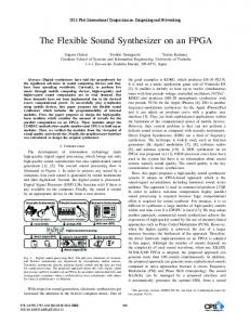
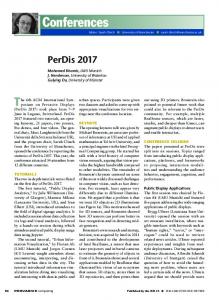
Figure 2: Pairs of input that should operates together for ordered input. Input that corresponds to the same circle are operated together in a radix-22 block. For this case, the first 4 input are operated at different time.
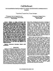
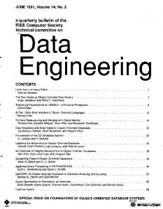
Figure 3: FFT block diagram (2)
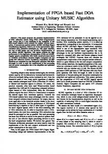
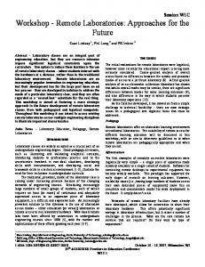
The IFFT operation is similar to FFT operation. Hence, a little modification to FFT operation is enough to have the architecture to calculate IFFT. III. FFT/IFFT BLOCK OVERVIEW FFT/IFFT block implemented in this paper uses single path radix-22 single path delay feedback architecture. The architecture that uses radix-22 ensures a less utilization of logic elements and multipliers. For 64-points case, it requires 3 radix-22 blocks and 2 twiddle factor (TF) multipliers. Input of this block enters the block serially. If the input that enters the block is in normal order, output of the FFT/IFFT block is in bit-reversed order (unordered). In ordinary FFT block, an additional reordering block is required to order the unordered output. However, if the unordered input enter the FFT/IFFT block, the output's order will be restored. In our architecture, we implement FFT operation with ordered input and IFFT operation with unordered input. Hence, there is no reordering block for applications that utilize FFT and IFFT operations in our architecture. It is to reduce some clock cycles latency.
Figure 4: Pairs of input that should operate together with unordered input. Input that corresponds to the same circle are operated together in a radix-22 block. For this case, the first 4 input are operated together.
A general control block is not required in this implementation. This is because each radix-2 2 block and TF multiplier block has its own control block based on its load signal and a counter inside each block. Figure 1 shows the block diagram of the FFT/IFFT block. A radix-22 block contains 2 blocks, those are radix-2A and radix-2B. For short, we call radix-2A and radix-2B as radix2X in general. Each radix-2X block is accompanied by a delay block. The delay block is used to make sure that one input data operates with the correct other input. For 16-points FFT, operation of radix-22 pairs of input are shown in figure 2 while for 16-points unordered IFFT are shown in figure 4. For the figure 2, the first stage, pairs 0-4-8-12 operate together, as well as pairs 1-5-9-13, 2-6-10-14, and 3-9-11-15. Contrast with ordered input, for unordered input, pairs 0-1-2-3 are operated together, as well as 4-5-6-7, 8-9-10-11, and 1213-14-15. Based on figures 2 and 4, for N-points FFT operation with ordered input, the first delay block has to make delay of N/2 clock cycles, then the second delay block has to make delay of N/4 clock cycles, and so on until the last block that gives delay of 1 clock cycle. Otherwise, for N-points IFFT operation with unordered input, the first delay block has to give delay of 1 clock cycle, then the next delay block gives delay of 2 clock cycles, and so on until the last block that gives delay of N/2 clock cycles. Block diagram of FFT block with delay block is shown in figure 3. For consecutive FFT-IFFT operations, one has to make sure that the FFT operation is finished before doing IFFT operation. If doesn't, register memory at the delay block for FFT operation will be overwritten by content for IFFT operation. For N-points operations, it is safe to wait for N
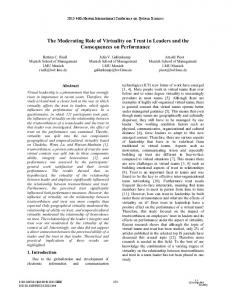
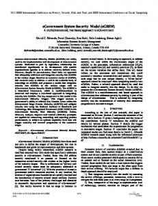
Figure 6: Radix-2B block diagram. This block is similar to radix-2A block except that some of the input is multiplied by -j for FFT and j for IFFT. Figure 5: Radix-2A block diagram
clock cycles after the first output is valid before doing the IFFT operation. The waiting period of N clock cycles can be used for other operations in frequency domain. Differences between FFT and IFFT operations can be seen from their equations. The FFT equation is as below,
(17)
B. Radix-2B Block Radix-2B block is just like radix-2A block with a little modification in the data input. Radix-2B block operates input according to equations below.
while IFFT equation is as below, N−1
∑ X (k ) e
j2π k n/N
.
(19)
(16)
n =0
1 x( n) = N
SA = [(c / Nd) % 2 == 0].
The operator '/' means integer division operation and '%' means modulo operation. In order to reduce area of implementation while maintaining the accuracy, output of adder is shifted by one bit to the right. Therefore, if the input of a radix-2A has format of Q1.15, the output has format of Q2.14 if FFT operation is performed or Q1.15 if IFFT operation is performed.
N−1
X (k ) = ∑ x( n) e− j 2 π k t/ N
load signal is active. Selector signal, SA, is active according to equation below.
k =0
It can be inferred that differences of FFT and IFFT operations are: • exponential factor in FFT are minus of exponential factor in IFFT; • in IFFT operation, the sum result needs to divide with N, while FFT does not. The differences between FFT and IFFT operations are handled in radix-2X blocks and TF multiplier blocks. IV. FFT/IFFT SUB-BLOCKS A. Radix-2A Block Radix-2A block is just like an ordinary radix-2 block. Radix-2A computes the equations below y m= x m+ xm+n (18) y m+n= x m− x m+n where xp is the p-th input, yp are the p-th output, n is delay of the delay block accompanying the radix-2A block, and m is arbitrary integer, m < n. Block diagram of radix-2A block is shown in figure 5. The control block inside a radix-2A block controls the selector of multiplexers and acknowledge signal based on how many delay clock cycles associated with the block, Nd. The control block also implements a counter, c, that starts with 0 and increases if load signal is active in each clock cycle. Acknowledge signal is active after Nd clock cycles after the
y m= z m+ z n+m y 2 n +m= z 2 n+m+(− j) z 3 n +m y n+m= z m−z n +m y 3 n= z 2 n +m−(− j) z 3 n+m
(20)
where zp, is the p-th input to the radix-2B, yp is the p-th output of the radix-2B, n is the delay of the delay block accompanying the respective radix-2B block, and m is the arbitrary integer, m < n. The data input is controlled whether it has to be multiplied by -j, j, or by 1. Block diagram of radix2B is shown in figure 6. Selector between j and -j is a signal that indicates if the process is IFFT. This is to handle the differences between FFT and IFFT operation in equation 16 and 17. The control block controls selector signals and acknowledge output signal. The acknowledge signal is simply like the acknowledge signal in radix-2A block. The control block also implements a counter, c, like radix-2A block. There are 2 selector signals from the control block, SA and SB. SA is a selector signal just like in radix-2A while SB is a selector signal for the left multiplexer. SA is active according to equation 19 while SB is active according to the equation below.
SB = [(c / 4floor(log4(Nd))) % 4 == 3].
(21)
Similar to the radix-2A block, output of adder inside this block is shifted by one bit to the right to reduce area used while maintaining accuracy. C. Twiddle Factor (TF) Multiplier Twiddle factor (TF) multiplier consists of 16-bit multipliers, adders, TF ROM, and a control block. In TF ROM, N values of e-j2πk/N saved in order from k=0 to N-1. For the first TF multiplier, it saves TF for N=64, and the next multiplier saves TF for N=16. In control block, there is a counter, c, implemented to set the address of TF ROM. The address of TF ROM depends on the counter value, c, and total values saved, N, as shown in the following equation. k = rev(c / N4) (c % N4)
(22)
where N4 = N/4, and rev(x) is 1 if x=2, 2 if x=1, and equals to x otherwise. If input of FFT/IFFT block is unordered, the counter, c, will count in bit-reversed order. The TF acquired in the address is then multiplied by input of this block. If the block does IFFT operation, the acquired TF is conjugated first before multiplied by the input. The multiplication operation is a complex multiplication, that is pr + j pi =(a r + j ai )(br + j bi ) pr = a r b r−a i bi p i = ar bi +a i b r .
(23)
Implementation of equations 23 directly needs 4 multipliers and 2 adders. Modification of equations 23 results the equations below, p r =a r (br +bi )−bi (a r+ a i ) p i =a r (br +bi )+br (a i −a r )
(24)
which needs 3 multipliers and 5 adders in the implmentation. Equations 24 needs less multiplier than equations 23. Hence, implementation of equations 24 results in smaller area than implementation of equations 23. D. Delay Block Every radix-2X block is accompanied by a delay block. We implement the delay block using RAM instead of registers to minimize its area. Besides RAM, a control block is also implemented to control read/write enable signal and address pointer. The address pointer increases if load signal is active and returns to 0 if it has reached an upper bound. Data in the address pointer is read and then is written with the input data. One challenge in implementation of the delay block is the difference of delay clock cycles between FFT and IFFT operations. To implement the delay block that be able to give
different delay, we add one additional input of this block to set the upper bound of address pointer. Implementation using RAM instead of register block is advantageous in area reduction. Table I shows the comparison of total logic elements and memory bits between implementation using flip-flops and RAM of 16 bits data. It shows that implementation using RAM can reduce many logic elements by utilizing its memory bits. In FPGA Cyclone II EP2C35F672C6, there are more memory bits available than logic elements. Therefore, it is better to utilize memory bits rather than logic elements in this case. V. PERFORMANCE OF FFT/IFFT BLOCK Our FFT/IFFT architecture has been implemented in FPGA using Altera DE2-70 board. The board uses Cyclone II EP2C35F672C6 FPGA chip. There are 483840 memory bits and 33216 logic elements available in the chip. The code is written in Verilog and compiled by Altera Quartus v12.1. Design parameters of this block are area and speed. Area is measured using total logic elements if implemented without embedded multiplier (TLEs). Speed is measured using maximum frequency and latency of the block. Table II shows the design parameters of the FFT/IFFT block for N=64 points. Performance of this block can be seen by comparing area of this block with area of other 64-points FFT blocks with 16 bits word length. Compared parameters are logic elements (LEs), embedded 9-bit multipliers (Mult), total logic elements if implemented without embedded multipliers (TLEs), and memory bits (Mem). Based on data in the table III, our FFT/IFFT block utilizes less area than FFT blocks from Quartus Mega function in all area aspects, i.e. logic elements, multipliers, total logic elements, and memory bits. We use some optimizations inside the FFT/IFFT block. Using 3 multipliers instead of 4 multipliers inside TF multiplier block can reduce utilized logic elements. Utilizing memory as delay block instead of using registers dramatically reduce utilized logic elements by utilizing memory bits. Besides logic elements utilization, we also compared clock cycles latency between our block and some 64-points FFT/IFFT block implementations. Table IV shows that our FFT/IFFT block requires less clock cycles than other FFT blocks. This is because we do not implement a reordering block to reorder unordered output. Commonly, a reorder block needs at least N clock cycles. Therefore, by not implementing any reorder block, it can save N clock cycles in operation. Output of FFT operation in our block is in bit-reversed order. If bit-reversed ordered input become the input of our IFFT operation, the output will be in normal order. Hence, using our FFT/IFFT block can reduce the number of cycles, but the operation in frequency domain should be processed in bit-reversed order or independent of order. In order to do 64-points FFT-IFFT operations consecutively, we should wait for 64 clock cycles after FFT operation before doing IFFT operation. Hence, in order to complete FFT-IFFT operations, it requires 210 clock cycles. This is less than twice of clock cycles of the other FFT blocks.
TABLE I AREA COMPARISON OF DELAY BLOCK IMPLEMENTATION
Logic Elements RAM Flip-flops 47 144 52 272 59 528 65 1040
Delay Clock Cycles 8 16 32 64
Memory Bits RAM Flip-flops 128 0 256 0 512 0 1024 0
TABLE II DESIGN PARAMETERS OF FFT/IFFT BLOCK
TLEs 2960
Mem 4608
Fmax (MHz) 84,55
N-Clk 73
Latency (ns) 863,4
TABLE III AREA COMPARISON OF FFT BLOCKS
FFT Blocks Our FFT/IFFT block FFT from Quartus MegaCore function with 4 multipliers[10] FFT from Quartus MegaCore function with 3 multipliers[10]
LEs 2264 4373
Mult 12 24
TLEs 2960 5765
Mem 4608 9984
4915
18
5959
9984
TABLE IV CLOCK CYCLES COMPARISON BETWEEN HW BLOCK AND SOME FFT BLOCKS
Blocks Our FFT/IFFT block Xilinx's FFT IP V1.0.5 [12] Altera Megafunction's [12] J. V. McCanny's[6] T. Chen's (1993) [7] T. Chen's (1999) [8]
Length (bits) 16 16 12 24 16 16
No. of cycles 73 192 112 130 208 222
TABLE V ACCURACY OF FFT/IFFT BLOCK
Configuration FFT only IFFT only FFT-IFFT
RMSE 1,60 x 10⁻³ 2,68 x 10⁻⁵ 1,39 x 10⁻³
ME 7,13 x 10⁻³ 1,14 x 10⁻⁴ 5,83 x 10⁻³
will be in bit-reversed order. Commonly, serial FFT blocks requires reorder block to reorder the output. In his paper, Saeed[5] states that reorder block is not necessary when performing FFT – IFFT because if the unordered FFT output goes to IFFT process, the order should be restored. However, he does not explain the architecture in detail. In this paper, we explain the architecture in more detail of FFT/IFFT block with no reordering block. With no reordering block, we have to implement delay blocks that is able to give different clock delays according to order of its input. Advantage of not implementing reordering block is that we can save N clock cycles for N-points FFT/IFFT operations. For 64-points FFT/IFFT operations, our block requires 73 clock cycles to complete the operation. Output of FFT operation of this block is in bit-reversed order. So the frequency-domain operations between FFT and IFFT operations will receive bit-reversed order input. Therefore, the implementation of this FFT/IFFT block is appropriate for frequency-domain operations which do not depend on frequency directly. In future, this block can be utilized for digital signal processing purpose to obtain high-speed circuits. One possible application of this block is implementation of real-time noise cancellation using Spectral Subtraction method. REFERENCES [1] [2] [3]
PE 0,05% 0,07% 0,34%
[4] [5]
Accuracy of this block was also measured using ModelSim simulation tools. Input of this block were randomly generated. Output from the FFT/IFFT hardware were then compared with FFT/IFFT results using Python programming. We tested this block using 3 configurations: FFT operation only, IFFT operation only, FFT and IFFT operations performed in one block. Comparison parameters are: root mean square error (RMSE), maximum error (ME), and percentage error (PE). Percentage error is equal to root mean square error divided by root mean square of output from Python programming. Table V shows the result. The error is mainly because of bit-shifts inside radix-2X blocks. Error of FFT – IFFT operation is larger than FFT operation and IFFT operation only. This is because in FFT – IFFT operation, the error is accumulated from the two operations. VI. CONCLUSION AND FUTURE WORKS There has been many implementations of serial FFT block. If input for serial FFT operation is in normal order, the output
[6] [7] [8] [9] [10] [11] [12]
S. F. Boll, “Suppression of Acoustic Noise in Speech Using Spectral Subtraction,” IEEE Trans. on Acoustic, Speech, and Signal Processing, Vol. ASSP-27, No. 2, 1979. J. W. Cooley and J. W. Tukey, “An Algorithm for the Machine Calculation of Complex Fourier Series,” Mathematics of Computation, Vol. 19, No. 90, pp. 297-301, 1965. N. Mahdavi, R. Teymourzadeh, M. B. Othman, “VLSI Implementation of High Speed and High Resolution FFT Algorithm Based on Radix 2 for DSP Application,” The 5th Student Conference on Research and Development, 2007. S. Zhang, D. Yu, “Design and Implementation of A Parallel Real-time FFT Processor,” Proc. 7th International Conference on Solid-State and Integrated Circuits Technology, pp. 1665-1668, 2004. A. Saeed, M. Elbably, G. Abdelfadeel, and M. I. Eladawy, “Efficient FPGA implementation of FFT/IFFT Processor,” Int'l Journal of Circuits, Systems and Signal Processing, Issue 3, Vol. 3, pp. 103-110, 2009. J. V. McCanny, D. Trainor, Y. Hu, T. J. Ding, “Rapid Design of Complex DSP Cores,” Proc. of the 23rd European Solid-State Circuits Conference, pp. 284-287, 1997. T. Chen and L. Zhu, “An Expandable Column FFT Architecture Using Circuit Switching Network,” The Journal of VLSI Signal Processing, Vol. 6, No. 3, pp. 243-257, 1993. T. Chen, G. Sunanda, J. Jin, “COBRA: A 100-MOPS Single-Chip Programmable and Expandable FFT,” IEEE Transactions on VLSI Systems, Vol. 7, pp. 174-182, 1999. E. Bidet, D. Castelain, C. Joanblanq, P. Senn, “A Fast Single-Chip Implementation of 8192 Complex Point FFT,” IEEE Journal of SolidState Circuits, Vol. 30, No. 3, pp. 300-305. 1995. Altera Corp., “FFT MegaCore Function User Guide.” [Online] Available on www.altera.com/literature/ug/ug_fft.pdf.. Accessed on Jan 27th, 2013. Y. Li and W. Chu, “Implementation of Single Precision Floating Point Square Root on FPGAs,” IEEE Symposium on FPGAs for Custom Computing Machines, pp. 226-232, 1997. K. Maharatna, E. Grass, U. Jaghold, “A 64-point Fourier Transform Chip for High-Speed Wireless LAN Application Using OFDM,” IEEE Journal of Solid-State Circuits, Vol. 39, pp. 484-493, 2004.