With respect to sound generation, electronic synthesizers get increased the attention in the field of computer music. One of the good examples is KORG, which ...
2013 First International Symposium on Computing and Networking
The Flexible Sound Synthesizer on an FPGA Suguru Ochiai Yoshiki Yamaguchi Yuetsu Kodama Graduate School of Systems and Information Engineering, University of Tsukuba 1-1-1 Ten-ou-dai Tsukuba Ibaraki, 305-8573, Japan
Abstract—Digital synthesizers have laid the groundwork for the significant advances in sound computing devices and they have been spreading worldwide. Currently, to perform live music through mobile computing devices, higher-quality and higher-speed sound computation are in vital demand. But these demands have not been implemented due to the devicesf scarce computational power. To successfully play symphonies using mobile devices, this paper proposes the flexible sound synthesizer which includes the programmability of internal modules. First, the paper proposes to design the high-quality basic modules which consider the amount of circuits for the parallel computation on an FPGA. These modules adopt the CORDIC methods thus enable smaller-sized FPGA to hold many modules. Then, we verified the modules from the viewpoint of sound quality and circuit size. Finally, the graphical user interface was introduced to design the original synthesizer.
the good examples is KORG, which produces DS-10 PLUS. It is used as a music application game soft of Nintendo DS [3]. It enables a melody to treat up to twelve simultaneous tones with four pseudo voltage controlled oscillators (VCOs)1 . KORG also produces iMS-20 monophonic synthesizer with two pseudo VCOs for the Apple iPhones [4]. DXi is another frequency-modulation synthesizer for the Apple iPhone/iPad and it can adjust an envelope curve with a graphic user interface [5]. They are both sophisticated applications within the limitation of the computational power of mobile devices. However, their current problem is they can not perform a delicate sound texture as compared with acoustic instruments. Direct Digital Synthesizers (DDS) are a kind of frequency synthesizer. The technique is widely used, such as function generators [6], digital modulators [7], [8], software radios [9], and antenna systems [10]. A DDS synthesizer on an FPGA was proposed in [11]. NIOS processor cores have been used in the system but there is no information about sound texture, namely sound quality. The sound quality is the key consideration in music synthesizers. Here, this paper proposes a high-quality sound synthesizer system. It adopts an FPGA-based approach which is the sound-signal accumulation including harmonic sound series addition. The approach is used in commercial products [12]B In order to achieve real-time computation, highly parallel sound processing is required because huge computational effort is required for sound synthesis. For instance, it is so difficult to synthesize a large number of high-quality sounds within real time even if a GPGPU is used [13]. We may adopt another approach; commercial sound synthesizers achieve the expression of high-quality sound by the use of memory-based approaches such as Pulse Coded Modulation (PCM). However, when the higher quality is achieved, the size of a larger memory becomes the bottleneck of the approach. Therefore, the direct hardware implementation on an FPGA is adopted in this paper; Although the number of sounds depends on the complexity of each sound waveform, when one XILINX XC6SLX100 FPGA is adopted, the proposed approach can generate more than 100 sounds simultaneously. In addition, the proposed approach can generate more sophisticated sounds compared to naive approaches because it covers Frequency Modulation (FM) and Phase Shift (transposing). The sound flexibility can be managed by a proposed interface and it automatically generates the optimal HDL from a sound
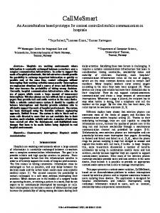
I. Introduction The development of information technology leads high-quality digital signal processing, which brings not only high-quality sound reproduction but also sophisticated sound generation [1], [2]. The overall sound processing flow is illustrated in Figure 1. In order to process any sound by a computer, first each sound is generated by sound instruments and then digitalized. Second, the digital sound is processed. Digital Signal Processor (DSP) LSIs function well if there is any available on the computer. Finally, the sound is output by an appropriate device in the form a user desires. Acoustic Instruments
Electric Instruments Electronic Instruments
Aerial vibration
Instrument vibration
record (A/D)
pickup (A/D)
Signal oscillation data save (D/D)
Digital sound processing direct output (D/A)
network output (D/D)
data save (D/D)
direct output (D/A)
Fig. 1. Digital sound processing flow: The physical vibrations of Acoustic and Electric instruments are digitalized by microphones and/or sensors. Electronic instruments directly generate digital sounds and the data are used for sound processing. The proposed approach unites the A/D, digital sound processing, and D/A modules on an FPGA. It can reduce intermediate files and management computers when a mobile-device user collaborates with others for musical performance via Internet.
With respect to sound generation, electronic synthesizers get increased the attention in the field of computer music. One of 978-1-4799-2795-1/13 $31.00 © 2013 IEEE DOI 10.1109/CANDAR.2013.22
1 The previous version, KORG DS-10, can treat six simultaneous tones by two pseudo VCOs.
104
dataflow graph via GUI. It opens new opportunities to digital music [14] and another possibilities to improvise freely are brought by network computing [15]. To offer better quality tones, this paper also proposes customized CORDIC methods of logarithmic functions for implementing an FPGA. The module combination makes variable tones and it enables the system to do parallel computation. This paper is organized as follows. Section II explains the component elements of tones. Section III outlines a synthesizer which is composed of five modules. Section IV proposes the flexible sound processor and how an FPGA can generate high quality tones. The experimental results are discussed and the synthesized tones are verified in Section V. Section VI concludes the paper.
Amplitude
Peak
Sustain Level Attack Decay
Release
Note on
Note off
Time
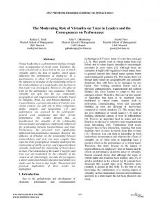
II. Tonal character Fig. 2. A sound envelope and four parameters: The period between Note-On and Note-Off can be decided by the physical key or a parameter Attack, Decay, Sustain level, and Release are also determined by users.
Tones can roughly be described by some component elements. The terms in the following list are chosen and redefined for this paper. Sound Envelope is the figure of many waveforms. Attack is the rising time to reach the peak. Decay is the time between peaks. Sustain is the sound amplitude until a released point. Release is the sound reverberation.
VCO
VCF
VCA
OUT
EG
Waveform is the figure of a one-cycle wave. Pitch is the cycle length, namely tonal frequency. Timbre is the shape. This influences the sound quality. Loudness is the amplitude, namely volume.
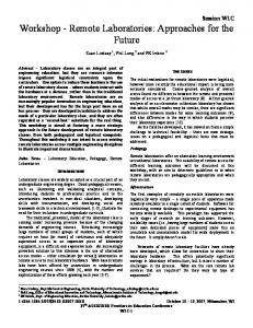
LFO Fig. 3. A structure of an analog synthesizer: In a VCO module, the frequency of a sound can be changed freely and the basic waveform can be selected from pre-installed waveforms such as a sine wave and a sawtooth wave. A VCO module can be synchronized to another VCO module even if their frequencies are different.
In general, a sound envelope is added after generating waveforms. Figure 2 shows the ADSR relationship by four parameters: Attack, Decay, Sustain, and Release. The Attack phase begins when a key is pressed (note on). The Release phase also begins when the key is released (note off). A natural sound can be made by changing ADSR parameters.
C. Voltage Controlled Amplifier (VCA) VCA is a module to generate sound effects; the modulation of the amplitude of a waveform makes a different waveform. The VCA setting can change temporal progress and enables amplitude alteration from moment to moment.
III. Synthesizer A. The Overview of Synthesizer Figure 3 shows the outline of an analog synthesizer [16]. The meaning of module abbreviations in Figure 2 is, Voltage Controlled Oscillator (VCO), Voltage Controlled Amplifier (VCA), Voltage Controlled Filter (VCF), Envelope Generator (EG), and Low Frequency Oscillator (LFO). VCOs, VCFs, and VCAs generate basic waveforms, thus a sound envelop of the output tones are added by EGs and LFPs.
D. Voltage Controlled Filter (VCF) VCF is used to filter and equalize computations. The cutoff frequency of VCF is controlled by the input signals. Then, it will shape the output waveform of VCO. The signals can be changed in temporal progress; for example, a VCF can change from low pass filter to high pass filter in real time. In this paper, this module is not discussed because our primary focus is the improvement of basic modules of VCOs and VCAs but not VCFs.
B. Voltage Controlled Oscillator (VCO) A VCO is a waveform generator. The superior modules can generate many kinds of periodical waveforms such as sinusoidal, triangle, saw-tooth, and rectangle waves. This paper adopts sinusoidal and triangular waveforms to offer higher-tonal quality. The reason which chooses two waveforms comes from the trade-offs between the sound quality and the amount of its hardware usage.
E. Envelope Generator (EG) EG controls VCOs, VCAs and VCFs, and generates time-variant voltage curves, namely sound envelopes. The characteristics of sound envelopes are specified by ADSR parameters as shown in Figure 2.
105
F. Low Frequency Oscillator (LFO)
sound processor
An LFO is generally a low-frequency oscillator under 20 Hz and it can generate the undulation and the swing of a sound by controlling VCOs, VCAs and VCFs. Both LFO and EG seem to have same functions but they are different. LFO makes the periodic change of a tone but EG can only change once for the whole of a tone. Our VCO is interchangeable with LFO in any cases, and therefore this module is not discussed in this paper.
∆Σ modulation sound processor ∆Σ modulation
IV. Flexible Sound Synthesizer on an FPGA The proposed sound synthesizer inherits characteristics from an analog synthesizer in Section III. The technical term for analog synthesizers is used in this section for highlighting the linkages between our proposed synthesizer and analog synthesizers. Hence, Digital Controlled Oscillator (DCO), Digital Controlled Wave (DCW), and Digital Controlled Amplifier (DCA) are described as VCO, VCF, and VCA, respectively. Incidentally, the frequency and the shape of each module can be changed by parameters which can be adjusted via our GUI; it is easy to change the Pitch of a waveform by users. Timbre is modified by the change of the basic waveform of a VCO module, and then is adjusted by the combination of basic modules. Loudness is controlled by VCA, namely ΔΣ modulation.
LFO
VCO
LFO
VCO
LFO
VCO
EG
VCA
EG
VCA
EG
VCA
LFO
VCO
LFO
VCO
LFO
VCO
EG
VCA
EG
VCA
EG
VCA
sound processor
FPGA
∆Σ modulation
Fig. 4. The overview of the proposed synthesizer: In fact, the proposed digital synthesizer is equivalent to a digital audio workstation, which includes not only a synthesizer but also a sequencer, a multi-track recorder, a mixer, and an effector. The sound processor in this figure can compute one or more sound waveforms and it can be considered as a track processor for a musical performance with multi sounds. Each processor can be connected to independent pins and output all sound in parallel.
A. The Overview of Sound Synthesizer Figure 4 shows the overview of the proposed sound synthesizer. The synthesizer has the layered structure of basic modules, processors, and its body parts. The performance of synthesizers is defined by the performance and number of processors. Each processor computes a tone simultaneously and this parallelism contributes real-time and high-quality sound computation. Processors are composed of many basic modules which were introduced in Section III. Thus, the number of modules is a key factor of the proposed synthesizer. It is only limited by the hardware resource; for example, more than 1,000 modules can be implemented on the largest FPGA.
VCO
VCO
VCO
VCO
VCA
VCA
VCA
VCA
basic waveform
Figure 5 shows some examples of the relationship between output waveform and the structure of sound modules. The user of proposed sound synthesizer need to design the tree of sound modules, which express the output sound. They can generate various sounds though rich and full sound requires complicated structure. A tone which is generated by a processor is represented by a 1-bit signal. All the signals may be superimposed for the final output of a synthesizer. On the other hand, each tone may be output to different output pins, namely speakers. Thus, the proposed synthesizer is designed as the entire output destination from sound processors, which can be freely changed. The ΔΣ modulation method is used for the parallel-serial conversion in this implementation. It is an approach of oversampling and noise shaping, which achieves highly accurate modulation [17]. Some earlier researches have
VCO
VCO
VCA
VCA
frequency modulation
additive synthesis
Fig. 5. A basic waveform can be output by the combination of one VCO and one VCA. If two VCOs and two VCAs are connected with the series, an frequency modulation function can be formed. If they are connected in parallel, an additive synthesis function is implemented. The users generate various waveform by designing a sound processor tree. In the tree, EGs and LFOs will be also used for rich and full sound.
already implemented ΔΣ modulation on an FPGA [18], [19] and this paper follows them. B. Basic Waveform in a VCO module: Sinusoidal Waveform It is necessary to calculate a trigonometric function to generate the sinusoidal waveform. In this paper, the sound synthesizer adopts the CORDIC (COordinate Rotation DIgital
106
g(θt )
Computer) method on an FPGA [20]. The CORDIC method is an iterative approach with the use of vector rotation. Firstly, it assumes a value of the function to be a vector in two dimensions. Then, it repeats the vector-rotation calculation to return the true value. The approach is composed of shift operations, add-subtract functions, and a small table reference. Therefore, the CORDIC method is widely used in many applications [21]. The function is f (θ s ) = A(1 + sinθ s ) (0 � θ s < 2π)
Ampletude
2A
(1)
yi+1 zi+1
= = =
xi − di yi 2−i , −i
yi + di xi 2 , zi − di atan(2−i )
π
Fig. 6.
2π
Triangular Waveform Function
By using Eq.6, Eq.5 is modified to ⎧ ⎞ ⎛ ⎪ fFPGA ⎟⎟ ⎜⎜⎜ ftone ⎪ ⎪ ⎪ ⎜ ⎪ nclk ⎟⎟⎠ , 0 � nclk < 2A ⎝ ⎪ ⎪ ⎨ fFPGA 2 ftone ⎞ ⎛ g(nclk ) = ⎪ ⎪ ⎪ fFPGA fFPGA ftone ⎟⎟ ⎜⎜⎜ ⎪ ⎪ ⎪ nclk ⎟⎟⎠ � nclk < , ⎪ ⎩ 2A ⎝⎜1 − f 2 ftone ftone FPGA
(2) (3) (4)
(7)
D. Amplitude computation in a VCA module
In Eqs.2-4, the rotation direction, di , takes a particular value: 1 or -1. Each rotation number enables the estimation of the magnitude of the iterated vector. The magnitude will be divided by the value after the totatation end. Thus, each CORDIC rotation requires two shift operations, three additions, and one table reference. The table has the information of the i-th θ (θi ), where tanθi is 2−i . It also has the magnitude of the vector in the state that the rotation is completed. The size of a table is 1,056 bit (=32x32(bit)+32(bit)) values when the repetition number is 32. The size is too small to implement on an FPGA and it does not become any problem.
The amplitude of a waveform is controlled in the VCA module and it may change over time. Thus, the value of ftone / fFPGA has to be calculated in real time. In this paper, VCA modules adopt the Newton-Raphson division for this computation. The division is a fast method and it has already applied to FPGA systems such as [22]. Fifteen iterations are considered from the experimental verification in this paper. E. Sound Envelope Control Although only a straight-envelope-line change has been discussed, the flexibility is introduced to EG modules. Figure 7 shows the rich-sound-envelope functions, and it can be produced by the calculation of the sinusoidal and the logarithmic function. The sinusoidal function is realized by the CORDIC method in SectionIV-B.
C. Basic Waveform in a VCO module: Triangular Waveform Our VCO module can treat triangular waveforms which is non-sinusoidal. The function is ⎧ ⎞ ⎛ ⎪ ⎜⎜⎜ 1 ⎟⎟⎟ ⎪ ⎪ ⎪ ⎜ ⎪ 0 � θt < π, 2A ⎝ θt ⎟⎠ ⎪ ⎪ ⎨ 2π ⎞ ⎛ g(θt ) = ⎪ (5) ⎪ ⎪ 1 ⎟⎟ ⎜⎜⎜ ⎪ ⎪ ⎟⎟⎠ ⎪ ⎜ < 2π, 2A θ π � θ 1 − ⎪ ⎝ t t ⎩ 2π
Amplitude
Peak
where A and θt means the amplitude of f (θt ) and the angle respectively. Figure 6 shows the function of g(θt ). Although Eq.5 corresponds to Eq.1, the implementation of g(θt ) on an FPGA is different from that of f (θ s ). To generate a triangular wave, g(θt ), the number of clock cycles, nclk , has periodicity of which the upper bound is fFPGA / ftone . fFPGA and ftone are the running frequency of a FPGA and the frequency of a tone, respectively. As shown in Eq.6, The nclk can correspond to θ s by the use of fFPGA and ftone . 1 1 nclk θt = 2π fFPGA / ftone
θt
0
where A and θ s mean the amplitude of f (θ s ) and the angle of the vector, respectively. The range of θ s is 0 � θ s < 2π. To reduce the computation, the region of the angle θ s can be restricted to 0 � θ�s < π/4 as shown in Eq.1. In the initial state, x0 , y0 , and z0 are 1, 1, and 45(=atan(1/20 )), respectively. Then, each value is calculated by the use of the following equations. xi+1
A
Sustain Level Attack Decay
Note on
Fig. 7.
Release Note off
Time
Advanced envelope by the sinusoidal and the logarithmic function
The CORDIC method can be applied to the logarithmic function [23]. It is assumed that xi > 0 and yi > 0 are the values of a sequence, respectively. When the logarithmic value
(6)
107
of xi is required, the following equation can be established on any terms. yi + log(xi ) = yi − log(Ai ) + log(Ai xi )
(8)
Here, when assuming that xi+1 = Ai xi and yi+1 = yi − logAi , Eq.9 is obtained from Eq.8. yi + log(xi ) = yi+1 + log(xi+1 )
(9)
If the parameter xi in Eq.9 presumes the range of xi is 1 − 2−i � xi < 1 + 2−i . If xi+1 becomes one, the logarithmic value of x0 will be obtained from yi+1 , because 0 + logx0 = · · · = yk + log(xk ) = · · · = yi+1 + log1 . . . log(x0 ) = yi+1
Fig. 8.
(10)
XILINX XC2V1000 board and iCon Cube Mini
Then, (xi , yi ) of the logarithmic function can be calculated in
xi
=
yi
=
xi−1 ∗ (1 − 1/2i ) : x ≥ 1 xi−1 ∗ (1 + 1/2i ) : x < 1
(11)
yi−1 + log(1 − 1/2i ) : x ≥ 1 yi−1 + log(1 + 1/2i ) : x < 1
(12)
software in this paper. It can treat spectrogram, spectrum, pitch contours, formant analysis, and waveform analysis. B. Results First of all, the FPGA runs at 100MHz and signals can be generated by dividing the frequency in modules. For example, if 100MHz is divided by 227,272, the 440Hz(A4) frequency is the output. 1) Sinusoidal Waveform: Figure 9 shows the sinusoidal-wave comparison of the result of [18] and the result of this study. There were little differences in Figure 9 (le f t). But, the difference has been clearly found in spectrum analysis as shown in Figure 9 (right). Although there was a noise in about 200Hz and about 900Hz to 3kHz in [18], the proposed approach achieved beautiful spectrum. Here, we could acknowledge the meaningfulness of our modified CORDIC and implementation methods. 2) Triangular Waveform: Figure 10 shows the triangular-wave comparison of the result of [18] and the result of this study. The result of [18] is different even in the waveform form the theoretical one in Figure 10 (le f t). On the other hand, the result of our proposed approach looks the same as the theoretical waveform. Figure 10 (right) shows the spectrum analysis. The result of [18] contained waves more than the ones included in the theoretical waveform. It dulled the wave edge of [18]. On the other hand, the result of the proposed approach is similar to the theoretical spectrum except for the signal strength. It indicates that we need to implement VCFs in good quality, and this improvement is carried over to the future works. 3) Envelope: Figure 11 shows the envelope comparison of the result of [18] and the result of this study. All base envelopes look the same in Figure 11 (le f t) but the details were different. The implementation of [18] was low sound resolution because of the adopted algorithm. In the proposed method, the sound resolution was improved and the waveform became smoother than [18]. The spectrum analysis is shown in Figure 11 (right). We could also acknowledge the meaningfulness of our modified CORDIC and implementation methods.
Although we can reduce some exceptions, it brings a problem; the error margin grows when the value of x is almost 1 and the iteration number i is less than 4. The reason is the rounding error which is caused by the reduction of the data width of log computation. This problem was settled as the following equations: if i < 4, xi
yi
⎧ ⎪ ⎪ ⎪ ⎨ = ⎪ ⎪ ⎪ ⎩ ⎧ ⎪ ⎪ ⎪ ⎨ = ⎪ ⎪ ⎪ ⎩
if i ≥ 4
xi
=
yi
=
xi−1 ∗ (1 − 1/2i ) : x > Ki xi−1 : Ki ≥ x ≥ 1 xi−1 ∗ (1 + 1/2i ) : x < 1 yi−1 + log10 (1 − 1/2i ) : x > Ki yi−1 : Ki ≥ x ≥ 1 yi−1 + log10 (1 + 1/2i ) : x < 1
(13)
(14)
xi−1 ∗ (1 − 1/2i ) : x ≥ 1 xi−1 ∗ (1 + 1/2i ) : x < 1
(15)
yi−1 + log10 (1 − 1/2i ) : x ≥ 1 yi−1 + log10 (1 + 1/2i ) : x < 1
(16)
V. Experimental Results and its Validation A. System Environment Figure 8 shows the photograph of an FPGA board and its audio interface. The test environment system is implemented on a single XILINX FPGA: Virtex II XC2V1000 [24]. The working frequency is 100 MHz and the design was written by Verilog HDL in Xilinx-ISE Project Navigator 10.1.03. The sound is output as a 1-bit signal from the FPGA. An USB audio interface, Cube Mini produced by iCON Corp. [25], was chosen for the instrument to evaluate the quality of sound signals. The sampling rate is 96/192KHz with 24 bit depth and it offers 22Hz to 22kHz (±0.1dB) frequency response. The Praat [26] is selected as the analytical
108
Sound Pressure Level (dB/Hz)
0.4219
Sinusoidal waveform by Praat [26]
0 -0.4218 1
Sound Pressure Level (dB/Hz)
-0.4139
1.01 Time(s)
Sinusoidal waveform by [18]
0 -0.4067 1
Sound Pressure Level (dB/Hz)
0.4164
1.01 Time(s)
Sinusoidal waveform by this paper
0 -0.4308 1
1.01 Time(s)
80
Spectrum of Sinusoidal waveform by Praat [26]
60
40 20
80
50
100
200
500
1000
2000
5000
104
2·104 Freq.(Hz)
104
2·104 Freq.(Hz)
Spectrum of Sinusoidal waveform by [18]
60
40 20
80
50
100
200
500
1000
2000
5000
Spectrum of Sinusoidal waveform by this paper
60
40 20
50
100
200
500
1000
2000
5000
104
2·104 Freq.(Hz)
(le f t) Waveforms. (right) Frequency responses. Comparison of Praat [26], a previous study [18] and our proposed approach of a sinusoidal wave.
1.01 Time(s)
Sound Pressure Level (dB/Hz)
Triangle waveform by Praat [26]
1.011 Time(s)
Sound Pressure Level (dB/Hz)
0.1248
1.011 Time(s)
Sound Pressure Level (dB/Hz)
Fig. 9.
0
-0.1243 1
0.1172
Triangle waveform by [18]
0
-0.1343 1.001
Triangle waveform by this paper 0.1308
0
-0.1228 1.001
Fig. 10.
80
Spectrum of Triangle waveform by Praat [26]
60 40 20 20
80
50
100
200
500
1000
2000
5000
104
2·104 Freq.(Hz)
104
2·104 Freq.(Hz)
Spectrum of Triangle waveform by [18]
60 40 20 20
50
100
200
500
1000
2000
5000
Spectrum of Triangle waveform by this paper 80 60 40 20 20
50
100
200
500
1000
2000
5000
104
2·104 Freq.(Hz)
(le f t) Waveforms. (right) Frequency responses. Comparison of Praat [26], a previous study [18] and our proposed approach of a triangular wave.
XC6SLX100 FPGA is adopted. The speedup is enough compared to [13], [18] though the comparison of sound quality between our approach and [13] could not be confirmed.
In addition, the result of an advanced-envelope implementation is shown in Figure 12. Both approaches correspond to the theoretical waveforms. The spectrum analysis is shown in Figure 13. Although it is not large, the proposed approach brought the noise which appears from 800 to 2,000Hz. The noises were overtone elements. We may need to implement other filters including VCFs for this type of noise.
TABLE I Circuit size of basic modules Module VCO (Sinusoidal Wave) VCO (Triangular Wave) VCA EG (Base) EG (Base+Sinusoidal F.) EG (Base+Logarighmic F.) EG (All) 1-bit translator
VI. Conclusion This paper proposes the high-speed sound synthesizer to cover the sophisticated waveform of music sounds. The circuit size is very compact as shown in Table I. It enables us to implement many modules and highly parallel computation; more than 100 sounds can be generated when one XILINX
LUTs 688 416 138 550 1093 939 1559 24
In the viewpoint of power consumption, it is still low since
109
- 0.200
0
2.961 Time(s)
EG modification by [18] 0.452
0
- 0.406
1.647 Time(s)
0
EG modification by this paper 0.508
0
- 0.521 0
21.04 Time(s)
Sound Pressure Level (dB/Hz)
0
Sound Pressure Level (dB/Hz)
0.200
Sound Pressure Level (dB/Hz)
EG modifucation by Praat [26]
80
Spectrum of Triangle waveform by Praat [26]
60 40 20 20
80
50
100
200
500
1000
2000
5000
104
5000
104
5000
104
2·104
Freq.(Hz)
Spectrum of Triangle waveform by [18]
60 40 20 20
80
50
100
200
500
1000
2000
2·104
Freq.(Hz)
Spectrum of Triangle waveform by this paper
60 40 20 20
50
100
200
500
1000
2000
2·104
Freq.(Hz)
(le f t) Waveforms. (right) Frequency responses. Comparison of Praat [26], a previous study [18] and our proposed approach of an envelope.
Fig. 11.
0.5172
Amplitude
0
0
-0.5254
11.2
Time (secs)
Amplitude
-0.5315
Sustain
Attack
Fig. 12.
Decay
0
0
18.95
Time (secs)
Amplitude
Amplitude
0.5159
Release
Attack
Decay
Release
(le f t) An envelope morphed by a triangular wave. (right) an envelope morphed by a sinusoidal wave
I/O pins are reduced by ΔΣ converters. The user can use this approach for mobile devices since the power depends on the size of circuits. The user can reduce and expand a sound-module tree freely. In addition, I/O pins are reduced by DS converters and the number of I/O pins is also changeable.
References [1] James Anderson Moorer. Signal processing aspects of computer music: A survey. Proceedings of the IEEE, 65(8):1108–1137, 1977. [2] Perry R. Cook. Sound production and modeling. Computer Graphics and Applications, IEEE, 22(4):23–27, 2002. [3] KORG DS-10 PLUS and KORG DS-10. http://www.korgds10synthesizer.com/. [4] KORG iMS-20 for iPad. http://www.korg.com/ims20. [5] DXi - the FM synthesizer for iPhone/iPad. http://www.taktech.org /takm/DXie/Manual.html. [6] Radu-Sebastian Marinescu and Corneliu Burileanu. Function generator by direct-digital frequency synthesis. In International Semiconductor Conference (CAS), volume 2, pages 427 –430, 2008. [7] Kangshun Li, Xiaoqiao Lu, Wensheng Zhang, and Feng Wang. Design and implement of digital modulator based on improved dds technology and dsp builder. In International Conference on Wireless
Lastly, a GUI was proposed for the synthesizer customization. The users can set some parameters of modules and their connections through the GUI. This design tool was written by Visual Basic and it can generate corresponding Verilog-HDL from the graph of modules automatically. The users can concentrate on designing their own synthesizers, which do not require any HDL experiences. This tool helps them create original synthesizers.
110
Sound pressure level (db/Hz)
Spectrum of a morphed envelope by a triangular wave 80
[16] 60
[17]
40
[18]
20 20
50
100
200
500 1000 Frequency (Hz)
2000
5000
104
2·104
[19]
Sound pressure level (db/Hz)
Spectrum of a morphed envelope by a sinusoidal wave 80
[20] 60
[21] 40
20 20
[22] 50
100
200
500
1000
2000
5000
104
2·104
Frequency (Hz)
[23]
Fig. 13. (le f t) Spectrum morphed by a triangular wave and (right) spectrum morphed by a sinusoidal wave
[24] [25] [26]
Fig. 14.
[8]
[9] [10]
[11] [12] [13] [14] [15]
Design tool for the proposed flexible synthesizer
Communications, Networking and Mobile Computing (WiCom), pages 1 –5, 2009. Jouko Vankka, Jonne Lindeberg, and Kari Halonen. Direct digital synthesizer with tunable delta sigma modulator. In International Symposium on Circuits and Systems, volume 1, pages I–917 – I–920, 2003. Bindiya Kamboj and Rajesh Mehra. Efficient FPGA implementation of direct digital frequency synthesizer for software radios. International Journal of Computer Applications, 37(10):25–29, jan. 2012. Takahide Nishio, Hsiao-Ping Tsai, Hsiao-Ping Tsai, and Hsiao-Ping Tsai. A high-speed adaptive antenna array with simultaneous multibeam-forming capability. IEEE Transactions on Microwave Theory and Techniques, 51(12):2483 – 2494, dec. 2003. Nonel Thirer and Aviram Souhami. Parallel processing for a DSP application using FPGA. In IEEE Convention of Electrical and Electronics Engineers, pages 389 –392, 2006. Kawai owner’s manual digital multi-dimensional synthesizer k5/k5m, 1987. OM712E. Bill Hsu and Marc Sosnick-P´erez. Real-time finite difference-based sound synthesis using graphics processors. Communications of the ACM, 56(6):54–62, 2013. Sergi Jord´a. Improvising with computers a personal survey (1989-2001). Journal of New Music Research, 31:1–10, 2002. ´ Alvaro Barbosa. Displaced soundscapes: A survey of network systems
111
for music and sonic art creation. Leonardo Music Journal, 13:53–59, 2003. Mark Jenkins. Analog Synthesizers: Understanding, Performing, Buyingfrom the legacy of Moog to software synthesis. Focal Press, 2007. Steven R. Nosworthy, Richard Schreier, and Gabor C. Temes. Delta-Sigma Data Converters: Theory, Design, and Simulation. Wiley-IEEE Press, 1996. Shuhei Yoshida and Yoshiki Yamaguchi. A study of an FPGA synthesizer. In International Conference on Audio Language and Image Processing, pages 1205 –1210, 2010. Shahrukh Athar, Muhammad Ali Siddiqi, and Shahid Masud. Design and FPGA implementation of a 2nd order adaptive delta sigma modulator with one bit quantization. In International Conference on Field Programmable Logic and Applications, pages 388 –393, 2010. Javier Valls, Martin Kuhlmann, and Keshab K. Parhi. Evaluation of cordic algorithms for fpga design. J. VLSI Signal Process. Syst., 32(3):207–222, nov. 2002. Wang Yang, Zhu ke jia, and Min Hao. A direct digital frequency synthesizer based on CORDIC algorithm implemented with FPGA. In International Conference on ASIC, volume 2, pages 832 – 835, 2003. Nikola M. Nenadio and Svetlana B. Mladenovic. Fast division on fixed-point DSP processors using newton-raphson method. In International Conference on Computer as a Tool, volume 1, pages 705 –708, nov. 2005. Naofumi Takagi and Shuzo Yajima. Hardware implementation algorithm for exponential and logarithmic functions (in japanese). RIMS Kokyuroku, 522:251–265, 1984. Memec. Virtex-IIT M V2MB1000 development board user’s guide, May 2002. Hookup Inc. icon CUBE mini. http://www.icon-global.com/Audio %20Interface Recording Cube%20Mini.htm. Paul Boersma and David Weenink. Praat: doing phonetics by computer. http://www.fon.hum.uva.nl/praat/.