Publication of Little Lion Scientific R&D, Islamabad PAKISTAN Journal of Theoretical and Applied Information Technology 30th June 2011. Vol. 28 No.2 © 2005 - 2011 JATIT & LLS. All rights reserved.
ISSN: 1992-8645
www.jatit.org
E-ISSN: 1817-3195
FPGA IMPLEMENTATION OF SCALABLE BANDWIDTH SINGLE CARRIER FREQUENCY DOMAIN MULTIPLE ACCESS TRANSCEIVER FOR THE FOURTH GENERATION WIRELESS COMMUNICATION 1
DHIRENDRA KUMAR TRIPATHI, S. ARULMOZHI NANGAI, 2 R. MUTHAIAH 1 Asst. Prof., Department of Information and Technology, SASTRA University, Thanjavur, India-613402 PG Student, M.Tech VLSI Design, SASTRA University, Thanjavur, India-613402 2
Assoc. Prof., Department of Information and Technology, SASTRA University, Thanjavur, India-613402 E-mail:
[email protected] ,
[email protected] ,
[email protected]
ABSTRACT In this paper, design and implementation of 4G SC-FDMA transceiver on FPGA is done and explained. Long Term Evolution (LTE) is next generation mobile communication standard from 3GPP, it is based on OFDMA) in Downlink Transmission and SC-FDMA in uplink Transmission. SC-FDMA is based on Frequency Division Multiple Access scheme. When compared with other multiple access scheme, it deals with the multiple users in a shared communication systems. SC-FDMA is also called as linearly pre-coded OFDMA, in the sense it has the additional discrete time Fourier transform (DFT) processing in SC-FDMA. The main advantage of SC-FDMA over OFDMA is low Peak to average power ratio, so the power transmission is low when compared. This work proposes a run time reconfiguration architecture for the SCFDMA. Where the bandwidth and sub carrier mapping schemes of SC-FDMA can be changed. Real time FPGA implementation results are captured in the Chipscope Pro Embedded Logic analyzer. Keywords: Orthogonal Frequency Division Multiple Access(OFDMA), Single Carrier-Frequency Division Multiple Access (SC-FDMA), Long Term Evolution (LTE), Discrete time Fourier transform (DFT) cyclic repetition are inserted between the blocks of SC-FDMA to efficiently eliminate time spreading between the blocks. The transmission bandwidth is divided into multiple subcarriers in parallel maintaining each subcarrier in frequency selective channel by utilising cyclic prefix or guard intervals. Utilisation of cyclic prefix prevents from the intersymbol interference between the blocks of SCFDMA. The linear convolution of the multipath channel is transformed into circular convolution, which enables the receiver to equalize each subcarrier present in the channel by scaling with a complex gain factor. The main advantage of SCFDMA over OFDMA is low Peak to Average Power Ratio (PAPR). As it has got lower PAPR, the power efficiency is high.[4]
1. INTRODUCTION 3GPP standard is focused on next generation cellular systems called Long Term Evolution (LTE)[1-2]. The scalable bandwidth of LTE is 1.5MHz- 20MHz. The LTE features are high peak data rate, flexibility of spectrum usage, low latency times, higher capacity per cell, etc. LTE is based on OFDMA in the downlink and SC-FDMA [1-3] in the uplink. LTE adopted SC-FDMA technique which is used in the uplink transmission of high data rate. Frequency division multiple access scheme is used in SC-FDMA and it deals with the multiple users on the basis of shared communication. SCFDMA is same as that of OFDMA system except the additional DFT processing. Single Carrier Modulation and Frequency domain equalisation are the techniques used in SC-FDMA which is same as that of OFDMA, in overall performance and complexity of the system. The guard intervals with
In the previous work of SC-FDMA transceiver the physical implementation of the process is not done in FPGA, whereas in this the implementation work is done and studied.
88
Publication of Little Lion Scientific R&D, Islamabad PAKISTAN Journal of Theoretical and Applied Information Technology 30th June 2011. Vol. 28 No.2 © 2005 - 2011 JATIT & LLS. All rights reserved.
ISSN: 1992-8645
www.jatit.org
The present work is concerned with the design and implementation of SC-FDMA transceiver for the 4th generation wideband communication on a single FPGA. The present work shows the schemes to change the bandwidth of the SC-FDMA transmitter at run time. The FPGA based implementation of subcarrier mapping and the relative hardware requirement is evaluated. The rest of the paper is organized as follow. Section 2 discusses about the SC-FDMA architecture and operation and section 3 discusses about the FPGA implementation process, section 4 gives implementation results and section 5 presents the conclusions and future scope.
E-ISSN: 1817-3195
blocks each containing n symbols. The next step after the modulation is to perform N point DFT which transform the time domain symbols {Xn} to frequency domain form DFT is a kind of discrete transform which is used in Fourier analysis. DFT transforms one function into another function which is called as the frequency domain representation {Xk}.[5] DFT equation is represented as, N −1
X k = ∑ xn e
−2π ikn N
k=0,1...N-1
(1)
n =0
Inverse discrete Fourier transform equation is represented as,
2. SC-FDMA ARCHITECTURE
xn =
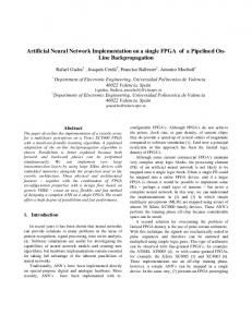
The transceiver of SC-FDMA is shown in the figure 1.It consists of following blocks, bit stream generation, bit to constellation mapping (QPSK), DFT, sub-carrier mapping, IFFT in the transmitter and the inverse blocks in receiver.
1 N
N −1
∑ Xke
2π ikn N
n=0,1....N-1
(2)
k =0
In the transmitter part of SC-FDMA, binary input signals are mapped into QPSK or QAM symbols. The modulated symbols {Xn} are in the form of
Figure 1 SC-FDMA Transceiver architecture The DFT input is of finite sequence of real or imaginary numbers. The symbols formed in time domain from the QPSK are changed to frequency domain using DFT.
IFFT in the systems. Depending on the bandwidth of the SC-FDMA number of subcarrier changes from the 72 (for 1.5MHz) to 1200 (for 20MHz). The two types of sub-carrier mapping are[6]
Sub-carrier mapping process done to the output the N-point DFT. Sub-carrier mapping is padding of zeros among the DFT outputs to match with size of
1. Localised mapping 2. Distributed mapping 89
Publication of Little Lion Scientific R&D, Islamabad PAKISTAN Journal of Theoretical and Applied Information Technology 30th June 2011. Vol. 28 No.2 © 2005 - 2011 JATIT & LLS. All rights reserved.
ISSN: 1992-8645
www.jatit.org
Localised Mapping: The output from the DFT is mapped to a subset of consecutive subcarrier, confining only to a fraction of system bandwidth. In the localised mapping the zero padding process is done either at the first or last, but the outputs of the DFT will be placed in the sequence order without any interchanging.
E-ISSN: 1817-3195
3. SC-FDMA IMPLEMENTATION ON FPGA The SC-FDMA transceiver is implemented on the Xilinx Virtex-5 ML501 board using Xilinx ISE 12.1[8] design suite. The modulation scheme preferred for the system is QPSK.
Distributed Mapping: The output of the DFT is assigned, non-continuously to the sub-carrier, over the entire bandwidth. In this case the zero padding operation is performed by calculating the L-1 zeros and the output data from the DFT are stored according to the size. The zero padding is done equally over the entire bandwidth. It is also called as Interleaved Mapping.[7] Both subcarrier mapping procedures can be seen in the figure 2.
First a LFSR is designed to work as the input bit stream generator for the transmitter. . LFSR is using 16 bit shift register whose input bit is linear function of its previous state. XOR is the only linear function of single bit so input bit of the shift registers are driven by XOR. The input bit stream is mapped into In-phase and Quadrature-phase symbols by tapping two MSB bits from the LFSR. Each QPSK real and imaginary symbol is of 16-bit size. The 32-point DFT block is generated using Xilinx IP Core generator. The 16-bit output from the QPSK is given as the input for the DFT. The core generated DFT consists of scaling factor, xn_index, xk_index, fwd_inv and enable pins. The scaling factor, xn_index and xk_index is of 6-bit. If the DFT operation is of forward transform then the fwd_inv is given 1. when the xk_index starts counting the output of the DFT is generated. For the implementation distributed sub-carrier mapping is selected. It was found that distributed sub-carrier mapping consumes less FPGA resources than the , localized subcarrier. In case of localized subcarrier mapping there is need of intermediate buffer memory which will store the DFT output until the all the zeros need to padded before the DFT output are padded. The sub-carrier mapping operation is done using a counter and multiplexer. Two 16-bit multiplexer are used, one for the real data and other for imaginary data .The counter output is given as the input for select line in multiplexer. Another input of the mux is given as constant zero value. The counter is a 2-bit counter and after the three clock cycles the output of the counter will be high. Than a multiplexer selects the input from the DFT otherwise a zero will be sent to IFFT block.
Figure 2 Sub carrier mapping After the mapping process, the frequency domain signals are transformed to time domain using a N (M