solve the ordinary differential equation describing the CNN. The design is ..... Focal plane implementation of 2d steerable and scalable gabor-type filters. J. VLSI ...
2006 International Joint Conference on Neural Networks Sheraton Vancouver Wall Centre Hotel, Vancouver, BC, Canada July 16-21, 2006
A Scalable FPGA Implementation of Cellular Neural Networks for Gabor-type Filtering Ocean Y. H. Cheung, Philip H. W. Leong, Eric K. C. Tsang, Bertram E. Shi Abstract— We describe an implementation of Gabor-type filters on field programmable gate arrays using the cellular neural network (CNN) architecture. The CNN template depends upon the parameters (e.g., orientation, bandwidth) of the Gabor-type filter and can be modified at runtime so that the functionality of Gabor-type filter can be changed dynamically. Our implementation uses the Euler method to solve the ordinary differential equation describing the CNN. The design is scalable to allow for different pixel array sizes, as well as simultaneous computation of multiple filter outputs tuned to different orientations and bandwidths. For 1024 pixel frames, an implementation on a Xilinx Virtex XC2V1000-4 device uses 1842 slices, operates at 120 MHz and achieves 23,000 Euler iterations over one frame per second.
I. I NTRODUCTION It is clear that biological systems perform feats of signal processing that we have not been able to approach using even the most sophisticated computers and signal processing techniques. Generally, biological based systems operate with greater functionality, lower power consumption and increased robustness than their man-made electrical counterparts. Although biological visual systems have been widely studied at the physiological, psychophysical and functional levels, our understanding of its signal processing mechanisms is still very rudimentary. One of the obstacles in this process is the difficulty of dealing with the vast amounts of processing necessary to test real-time temporal models of the visual system. Although parallel clusters offer enormous amounts of computing power, issues concerning latency, power consumption and volume constraints are limiting in many applications. To address this issue, implementations using subthreshold analog VLSI techniques have been proposed and real-time models of early vision systems have been developed. Analog VLSI is an excellent match to the distributed parallel computation present in biological systems. It offers high speed, high density and low power consumption. However, it has the disadvantages of long design time, low signal to noise ratio and is best suited for simple, regular designs. Field programmable gate arrays (FPGAs) have complementary properties in that design times are short, arbitrary dynamic range can be achieved and complex control logic is relatively easy to implement. We believe that hybrid systems which process information in both domains are able to combine their benefits. In visual systems, as information travels from the retina to the cortex, neurons become progressively more selective to complex stimuli [1]. Cells in the retina are sensitive to position, size, temporal frequency and color. In the higher 0-7803-9490-9/06/$20.00/©2006 IEEE
stage of processing, such as the primary visual cortex (V1), additional selectivity to orientation, direction of motion and binocular disparity have been recorded. A large proportion of cells in V1 can be modeled by a orientation selective neuron which consists of a Gabor-type filter followed by a nonlinear element [2]. In this paper, we first present a high performance FPGAbased cellular neural network which implements a Gabortype filter. 1 This is a building block element which we intend to use with different parameters to model cells in V1. The application of the Gabor-type filter in a neuromorphic system consisting of an analog VLSI retina chip interfaced to our Gabor chip is also presented. The retina chip serves as an imager and transmits its output to the FPGA via an address event representation (AER) transceiver. By combining both analog VLSI chips and digital chips (e.g. DSP chips, microprocessors, and FPGA chips), we hope to make real-time implementations of early vision models and visualize their temporal behaviour, while achieving a level of performance, integration, power consumption, area and flexibility not possible using any technology in isolation. An analog VLSI silicon retina is used for image acquisition. Neuronal activity in the retina is transmitted to an FPGA using the address event representation (AER) communication protocol [3], [4], [5], [6]. The AER scheme is not widely used in reconfigurable computing circles and offers an efficient communications scheme when activity is sparse, as in the case of most biologically inspired systems. Using AER, multiple neuromorphic chips can be interconnected in a modular manner and large networks of Gabor chips, each modeling different cells in the visual system can be implemented. A preliminary version of this paper was published in [7]. The design presented has the following contributions: • We present a novel, flexible and scalable architecture for modeling early vision using cellular neural networks (CNNs) on Field Programmable Gate Arrays • The functionality of the Gabor-type filter can be changed at runtime by downloading different CNN templates • We describe how a system can be developed using a front end analog VLSI retina system to study the early vision models in V1, and which operates in real time • We propose and explore the simulation of neural activity on FPGAs using an AER interface 1 This research was supported in part by Hong Kong Research Grants Council.
15
The rest of the paper is organized as follows. In Section II, Gabor-type filters and their implementation using cellular neural networks are introduced. Next, in Section III the architecture of an FPGA-based Gabor-type filter is described. Results obtained from our implementation are in Section IV. Finally, conclusions are drawn in Section V. II. M ODEL A Gabor filter can be represented by the complex valued convolutional kernel [8] 1 − x2 +y2 2 j(ωx x+ωy y) e 2σ e (1) 2πσ 2 where σ, ωx , ωy are real constants. The even kernel is cosine modulated and the odd kernel is sine modulated and hence two filers are 90 degrees out of phase. Pollen and Ronner suggested that adjacent neurons in visual cortex have even and odd symmetry [9] and therefore Gabor-filter can model receptive field profiles. Such filters can be used to model the receptive fields of neurons in the visual cortex [2], [10] and have applications in stereo vision [11], texture segmentation [12], and motion analysis [13]. Cellular neural networks (CNN) can be used to implement Gabor-type filters, where the functions modulating the complex exponentials are not necessarily Gaussian [14]. In this section, we describe the equations necessary to implement a Gabor-type filter and refer readers to [14] for a full derivation. The CNN formulation leads to a particularly simple parallel implementation and is adopted in this work. Let uij , xij and yij represent the input, state and output pixels of an image respectively. The dynamics of the CNN are governed by the differential equation X X dxij τ = fij = −xij + akl ykl + bkl ukl (2) dt g(x, y) =
kl∈Nr
kl∈Nr
where akl represents the feedback template and bkl represents the control template. The output of the CNN is commonly assumed to be a sigmoidal nonlinearity, yij =
1 (|xij + 1| − |xij − 1|) 2
(3)
which is linear in the range [−1, 1] and saturates at −1 or +1 outside this range. Since the Gabor-type template is intended to operate in the linear region, for simplicity we will assume in the following that yi,j = xi,j . Finite difference methods can be used to solve the ordinary differential equation (ODE) in Equation 2. Although techniques such as Runga Kutta methods with higher accuracy exist, the first order Euler method was selected for its simplicity and minimal state. Euler’s method approximates the trajectory of the differential equation at discrete timesteps of size ∆t according to the formula: xij (t + ∆t ) = xij (t) + hfij (t)
(4)
Where fij is defined in equation 2 and h = accumulated error for Euler’s method is O(h). For a 3 × 3 CNN, the feedback template, akl is a00 a10 a20 a01 a11 a21 a02 a12 a22
∆t τ .
The
and for the special case of a Gabor-type filter [15], the template is 0.0 α2y e−jΩy 0.0 α2x ejΩx −2(α2x + α2y ) α2x e−jΩx . 0.0 α2y ejΩy 0.0 The control template, bkl is 0 0 0
given by 0 0 β 0 . 0 0
The spatial transfer function of this filter for an input image that is constant in time is H(ωx , ωy ) = H(ωx , ωy ) ≈
1+
HΩ 2−2 cos(ωy −Ωy ) 2−2 cos(ωx −Ωx ) + (∆Ωx )2 (∆Ωy )2 HΩ
1+
(ωx −Ωx )2 (∆Ωx )2
+
(ωy −Ωy )2 (∆Ωy )2
(5)
where H(Ω) = (∆Ωx )
2
=
(∆Ωy )
2
=
β 1 + α2x (2 − 2 cos Ωx ) + α2y (2 − 2 cos Ωy ) β HΩ α2x β HΩ α2y
The constant HΩ is the maximum gain of the filter, which occurs at the spatial frequency (ωx , ωy ) = (Ωx , Ωy ), corresponding toqa sine wave grating with spatial frequency Ω magnitude Ω = Ω2x + Ω2y and orientation θ = arctan( Ωxy ). The terms ∆Ωx and ∆Ωy are referred as the half bandwidths in x and y, since the transfer function drops to half its maximum value at spatial frequencies (ωx , ωy ) = (Ωx ± ∆Ω, Ωy ) and (ωx , ωy ) = (Ωx , Ωy ± ∆Ω). The parameter β provides control over the filter gain. In the following, we assume that β is chosen so that the filter has unity gain, i.e., HΩ = 1. By changing the values of Ωx , Ωy , ∆Ωx and ∆Ωy (or equivalently Ωx , Ωy , αx and αy ), the Gabor-type filter can be tuned to respond to different orientations and spatial scales. π π cos( π4 ), Ωy = 12 sin( π4 ), For example, if we choose Ωx = 12 π and ∆Ωx = ∆Ωy = 36 (i. e., αx = αy = 13.2), we obtain a filter tuned to orientation θ = 45◦ and spatial frequency π magnitude Ω = 12 . Keeping the values of ∆Ωx and ∆Ωy π unchanged, but modifying Ωx to 12 and Ωy to 0, we obtain a filter tuned to the same bandwidth and spatial frequency, but orientation θ = 0◦ . The corresponding values of αx and αy are approximately unchanged. If we scale the spatial
16
Control unit Templates
Gabor-type filter core Input Block RAM
Gabor-type filter core
...
Output Block RAM
Gabor-type filter core
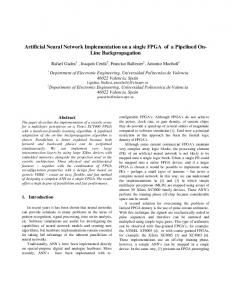
Fig. 1. General Architecture for producing multiple maps from a Gabortype filters cell.
frequency and the bandwidth by the same factor, we can implement a filters of varying scales, i. e., they have identical impulse responses except for a spatial scaling. Thus, we can use this system to model the outputs of orientation tuned neurons in the V1, where it is thought that each retinal location is served by a set of neurons tuned to different orientations and spatial scales. The orientation coverage is commonly assumed to be uniform, and the spatial scales appear to vary over a range of 4 octaves [16]. III. I MPLEMENTATION The approach used in our FPGA implementation of the Gabor-type filter was to develop a pipelined datapath which can perform the required complex multiply accumulate operations for the solution of Equation 2 using Euler’s method. Inputs, templates and outputs are stored in internal memories of the FPGA. In order to model responses of cells in the primary visual cortex, the output of a large number of Gabor filters tuned to different orientations, scales and frequencies are desired. In our implementation, these can be easily adjusted as they are parameters stored in memory and can be modified by the serial communication interface. Hence a single core can process data in a time multiplexed manner with different parameters. Multiple cores can be also used to increase performance as illustrated in figure 1. Gabor-type filters have a complex valued convolutional kernel, the data format with complex value is used. As fixedpoint arithmetic implementations require less area, two’s complement fractions are used. In our implementation, a core is built based on 16-bit fixed-point arithmetic and the Euler integration method. The data format consists of two 16-bit words which are used for the even and odd kernels of equation 1. The 16-bit words consist of a 4-bit integer part and 12-bit fractional part. For the VGA interface, image pixels are represented by an 8-bit number. We chose h = 0.25 for our implementation. Since ∆t is determined by the speed of the Euler core iteration, which is 43µs in our implementation, this corresponds to a time constant τ = 0.17ms. The actual time constant is 0.68ms due to the accumulated error of Euler’s method. The mean square error
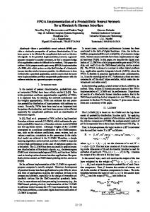
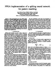
of precision is measured to be 5.24 × 10⁻⁵ in the simulation of Euler core using a high precision floating point computer. In figure 2, the design of the Euler core is shown. Inside the dotted box, template registers are multiplied by the current state variables. The computation is pipelined to achieve a throughput of one multiplication per cycle. The multiplier is generated using the Xilinx Core Generator and has a latency of three clock cycles. The SRL16E shift registers blocks are used to match the latency of the pipelined units. The datapath of Euler core has latency of 17 cycles. In every clock cycle, one of the state variables is read from the current block ram sets and then multiplied with the value in the template register. The Euler core calculates ΣAx in five cycles. To reduce the critical path, the multiplier result is latched and accumulated (Add1). ΣAx is then added to the current state variable and pixel input (Add2). Assuming h = 0.25, the result is then shifted right by two (with sign extension). Finally, the current state variable is again added to the result (Add3) and written to the next block ram. The above procedure is repeated for all pixels to compute a timestep. In our 16-bit, 32 × 32 pixel array example, since complex numbers are used, we require 2 sets of RAM with 32-bit word length totalling 64Kb. These memories are instantiated as four 16Kb dual port block RAMs (primitive components in Xilinx Virtex-2). Our pipelined Euler core datapath achieves a 120M Hz clock rate which corresponds to 120M Hz/(5 × 32 × 32) = 23K Euler frame-iterations per second. A. Integration with Silicon Retina Our Gabor-type filter is used as the processing unit in a silicon retina system as shown in figure 3. In the system, a silicon retina, leaky integrators, Gabor-type filter core, and spike generator are integrated. The silicon retina is a custom designed analog VLSI chip [17] and the other components are implemented on an FPGA. The image from the silicon retina is encoded as a spike train using the AER protocol [3], [4], [5], [6]. They are reconstructed in digital format via leaky integrators and the values written to block ram for the Gabor-type filter core. After the output pixel array has been computed by the Gabortype filter core, an AER output spike train is generated to simulate the neuronal activities of ON and OFF channel in spiking neuron interface. Finally, the output spike train is passed through another leaky integrator to a VGA interface and visualized on a monitor. 1) Address-event representation (AER) Interface: Communications between the FPGA and silicon retina are performed using an AER protocol and images are encoded in the form of spike trains. The AER protocol scheme is shown in figure 4. An address event consists of sequences of addresses. The ReqY signal is brought high when there is an address event. For a particular row and column address, the ∼ ReqX signal is taken low. The receiver acknowledges by driving Ack signal low. In the sequence of address, the first address is a chip address
17
Pipelined stage for Ax Template A
*
Current Block RAM set (x)
Latch
+
Add1
+
SRL16E x[i,j] SRL16E
Add2
+ Add3
Fig. 2.
FPGA Silicon Retina
Architecture of Euler core
Chip1
Chip Addr
Input block RAM
AER interface
Row Addr
VGA Display
Pixel Array Input
>>2
x[i,j]
Next Block RAM set (xn)
SRL16E
Gabor-type filter core
VGA Interface
Col Addr
Row1 Col1
Col2
Row2 Col3
Col4
Col5
Col6
Addr rdy AER output
AER interface
Fig. 3.
Addr
Spiking neuron interface
Output block RAM
Fig. 5.
AER interface scheme in the FPGA
Architecture of silicon retina system
Chip1
Row1
Col1
Col2
Col3
Chip2
the digital data from incoming spike trains. The value of the data is dependant on the frequency of spikes and is given by the formula
ReqY
xt+1 = xt × e
~ReqX Ack
Fig. 4.
AER interface scheme
and the second address is a row address. This is followed by multiple column addresses which represent the spike trains. A different AER scheme is used in the FPGA as shown in figure 5. The neuron in row1 and col1 fires a single spike, followed by the neuron address row1, col2. After the spikes from row1 are transmitted, row2 is sent. Compared to the original AER scheme, which operates asynchronously with a serial word format, the FPGA scheme uses parallel addresses and a synchronous scheme. This results in improved speed within the FPGA as the transmission of a spike takes a single clock cycle whereas the original scheme requires multiple clock cycles. 2) Leaky integrator: In order to simulate the activities of retinal neurons, spike trains are used. The frequency of the spike train indicates the degree of neuron stimulation. However, a spike train is difficult to process using synchronous digital logic. Therefore, a leaky integrator is used to form
−t τ
+ nC
(6)
where x(t) is the neuron activity at time step t (10ms refresh rate of VGA interface), τ is a time constant (set to 0.111 s), n are the number of incoming spikes during t and 1 C is a constant determined by manual tuning ( 32 ). 3) Spiking neuron interface: The Euler core operates on pixel maps and the interface shown in figure 6 is required to convert pixel maps in a serial-word format to produce AER spike trains. The Euler core operates at 120 M Hz whereas the refresh rate of VGA interface operates at 100 Hz. The pixel values from the Euler core are accumulated in spiking neurons, one being used for each pixel location. The accumulated pixel value is checked against positive and negative thresholds. If the value is larger than a positive threshold, a pulse is fired on the ON channel and a value subtracted from it. Values smaller than a negative threshold are treated similarly, pulses being fired in the OFF channel. Finally, spikes are converted to the AER protocol format and sent to a display via a VGA interface. This AER output can also be sent to other chips for further processing. IV. R ESULTS In [18], Choi et. al. presented an analog VLSI retina system with a Gabor-type filter VLSI chip. The same AER
18
neuron interface was approximately four months, and the corresponding VLSI Gabor-type filter design required six months plus an additional three months for chip fabrication. Besides the scalability and flexibility offered in our FPGA implementation, the design cycle is shorter, allowing for more sophisticated models to be developed.
Pixel values from Euler core
+
V. C ONCLUSIONS
dina fire
douta Block ram
Comparator >threshold
doutb dinb
Threshold
-
An implementation of Gabor-type Filters on field programmable gate arrays using cellular neural network (CNN) architecture is described. Compared to other analog implementation of Gabor-type filters, our implementation on FPGAs have advantages of scalable and flexility. High degree of parallelism can be achieved by instantiate more Gabor-type filter core operates for different orientations. In particular, we hope that it can be used to test and refine models concerning processing in V1. R EFERENCES
Fig. 6.
Architecture of spiking interface
input/output format is used in our FPGA-based Gabortype filter implementations such that both system are fully compatible. The Euler core was implemented on a Celoxica RC200 platform which is populated with a Xilinx XC2V1000-4. Our 16-bit Euler core runs at 120M Hz and uses 759 slices (14% of the logic resources of the chip). Adding the leaky integrators, spiking neuron interface, AER interface and VGA interface increases the total area utilization to 1842 slices. A single Euler core achieves 23, 000 Euler iterations over one frame per second compared to the result of 16, 000 Euler iterations over one frame per second in the corresponding C program which runs on a 3GHz Pentium 4 machine. The power consumption of the analog Gabor chip (0.25µm technology at 2.5 − 3 V ) and its peripherals as described in [18] is 44.1mW . The power consumption of the FPGA chip (0.12µm technology at 1.5 V ) and all the peripherals on the RC200 platform in the reset state is 1.929W . This increases to 1.946W when the Euler core is processing. The spatial impulse response of the FPGA-based Gabor type filter was measured by stimulating the pixel located at (17, 17) with a 500Hz spike train from a pattern generator. Different CNN templates were downloaded to Euler core for different orientations with spatial frequency magnitude Ω = π 4 . Figure 7 shows the output display with vertical, horizontal and diagonal orientations from about 30000 spikes collected using a logic analyzer. A ring pattern in white with a black background is displayed on a LCD monitor and captured using the silicon retina. The image is processed by the FPGA-based Gabortype filter processor and the result is shown in figure 8. The spatial frequency of the Gabor-type filter is set to be π3 . The design time for the FPGA-based components including Euler core, leaky integrator, AER interface and spiking
[1] D.G. Albrecht and W.S. Geisler. Motion selectiveity and the contrast response function of simple cells in the visual cortex. Vis. Neurosci., 7:531–546, 1991. [2] J.G. Daugman. Two-dimensional spectral analysis of cortical receiptive field profiles. Vision Research, 20:847–856, 1980. [3] K.A. Boahen. Point-to-point connectivity between neuromorphic chips using address events. IEEE Trans. Circuits Syst. II, 47:416–434, May 2000. [4] K.A. Boahen. A burst-mode word-serial address-event link-i: transmitter design. IEEE Transactions on Circuits & Systems I-Fundamental Theory & Applications, 51:1269–1280, 2004. [5] K.A. Boahen. A burst-mode word-serial address-event link-ii: receiver design. IEEE Transactions on Circuits & Systems I-Fundamental Theory & Applications, 51:1281–1291, 2004. [6] K.A. Boahen. A burst-mode word-serial address-event link-iii: analysis and test results. IEEE Transactions on Circuits & Systems IFundamental Theory & Applications, 51:1292–1300, 2004. [7] Ocean Y. H. Cheung and Philip H. W. Leong and Eric K. C. Tsang and Bertram E. Shi Implementation of Gabor-type filters on Field Programmable Gate Arrays. Proceedings of the IEEE International Conference on Field-Programmable Technology (IEEE ICFPT), to be appeared. [8] D. Gabor. Theory of communication. J. Inst. Elect. Eng. London, 93:429–457, 1946. [9] D. A. Pollen and S. Ronner. Phase relationship between adjacent simple cells in the visual cortex. Science, 212:1409–1411, 1981. [10] S. Marceljia. Mathematical description of the responses of simple cortical cells. J. Opt. Soc. Amer., 70:1297–1300, Nov 1980. [11] T. Sanger. Stereo disparity computation using gabor filters. Biol. Cybern., 59:405–418, 1988. [12] N. Porat and Y.Y. Zeevi. Localized texture processing in vision: Analysis and synthesis in gaborian space. IEEE Trans. Biomed. Eng., 36:115–129, Jan 1989. [13] D.J. Fleet. Measurement of Image Velocity. Kluwer Academic Publishers, 1992. [14] B.E. Shi. Gabor-type filtering in space and time with cellular neural networks. IEEE Trans. Circuits Syst. I, 45:121–132, Feb 1998. [15] B.E. Shi. Focal plane implementation of 2d steerable and scalable gabor-type filters. J. VLSI Signal Processing, 23:319–334, 1999. [16] R. L. DeValois, D. G. Albrecht, and L. G. Thorel. Spatial frequency selectivity of cells in macaque visual cortex. Vision Research, 22:545– 559, 1982. [17] K. A. Zaghloul. A silicon implementation of a novel model for retinal processing. PhD thesis, University of Pennsylvania, 2001. [18] T. Y. W. Choi, B. E. Shi, and K. Boahen. An on-off orientation selective address event representation image transceiver chip. IEEE Transactions on Circuits and Systems-I: Regular Papers, 51:342–353, 2004.
19
5
10
10
10
10
15
15
15
15
20
20
20
20
25
25
25
25
30
30 5
10
15 pixel
20
25
30
30
30
(a) The even output with vertical tuning. White/Black = 9/34 Hz.
5
10
15 pixel
20
25
30
(b) The odd output with vertical tuning. White/Black = 14/14 Hz.
5
10
15 pixel
20
25
5
30
(c) The even output with 45 degree tuning. White/Black = 10/35 Hz.
10
10
10
10
15
15
15
15
pixel
5
pixel
5
20
20
20
20
25
25
25
25
30 5
10
15 pixel
20
25
30
30
(e) The even output with horizontal tuning. White/Black = 9/36 Hz.
5
10
15 pixel
20
25
20
25
30
30
30
(f) The odd output with horizontal tuning. White/Black = 17/15 Hz.
15
(d) The odd output with 45 degree tuning. White/Black = 17/14 Hz.
5
30
10
pixel
5
pixel
pixel
pixel
5
pixel
5
pixel
pixel
5
5
10
15 pixel
20
25
30
(g) The even output with 135 degree tuning. White/Black = 10/36 Hz.
5
10
15 pixel
20
25
30
(h) The odd output with 135 degree tuning. White/Black = 16/15 Hz.
Fig. 7. The output of spatial impulse response. (The maximum firing rate of ON channel is represented by white and maximum firing rate of OFF channel is represented by black)
5
5
5
5
10
10
10
10
15
15
15
15
20
20
20
20
25
25
25
25
30
30 5
10
15
20
25
30
(a) The even output with vertical tuning. White/Black = 227/99 Hz.
30 5
10
15
20
25
30
(b) The odd output with vertical tuning. White/Black = 170/184 Hz.
30 5
10
15
20
25
30
(c) The even output with 45 degree tuning. White/Black = 231/102 Hz.
5
5
5
5
10
10
10
10
15
15
15
15
20
20
20
20
25
25
25
25
30 5
10
15
20
25
30
(e) The even output with horizontal tuning. White/Black = 221/89 Hz.
30 5
10
15
20
25
30
(f) The odd output with horizontal tuning. White/Black = 167/181 Hz.
15
20
25
30
(d) The odd output with 45 degree tuning. White/Black = 172/186 Hz.
5
30
10
30 5
10
15
20
25
30
(g) The even output with 135 degree tuning. White/Black = 234/105 Hz.
5
10
15
20
25
30
(h) The odd output with 135 degree tuning. White/Black = 174/192 Hz.
Fig. 8. Output of ring pattern (The maximum firing rate of ON channel is represented by white and maximum firing rate of OFF channel is represented by black)
20