used because it might be computationally intensive in some applications, however, the available current hardware resourc
FPGA IMPLEMENTATION OF THE MORPHOLOGICAL OPERATOR PECSTRUM FOR REAL TIME IMAGE RECOGNITION APPLICATIONS Juan Manuel Ramírez Cortés 1, Jorge Martínez Carballido1, Vicente Alarcón Aquino2, Miguel Angel Moreno Cedeño1, Emmanuel Morales Flores1 1.Instituto Nacional de Astrofísica, Optica y Electrónica, Coordinación de Electrónica, Tonantzintla, Puebla, C.P.72760, Mexico 2.Universidad de las Américas Puebla, Departamento de Electrónica, Cholula, Puebla, Mexico
Abstract Morphological image processing is a nonlinear theory and technique to quantitatively describe shape‐oriented operations in a digital image. The morphological operators are described by combinations of a basic set of numerical manipulations between an image A and a small object B, called a structuring element, which can be seen as a probe that scans the image and modifies it according to some specified rule. An important morphological operator is the pattern spectrum or pecstrum, defined through the morphological operations erosion and dilation with the same structuring element applied sequentially. This operator decomposes the target image in morphological components according to the shape and size of the structuring element, providing a quantitative analysis of the morphological content of the image. Although it presents excellent properties as a shape extractor, with invariance to translation and rotation, pecstrum has not been extensively used because it might be computationally intensive in some applications, however, the available current hardware resources overcome this disadvantage. In this work, an implementation of the pecstrum operator using a FPGA NexysII, Xilinx, Spartan 3E, is presented. The system is currently under test in some projects based on real time image recognition, such as biometric and cytology applications. 1. Introduction Mathematical morphology is a geometric approach to non linear image processing that was developed as a powerful tool for shape analysis in binary and grayscale images. Morphological operators are defined as combinations of basic numerical operations taking place over an image A and a small object B, called a structuring element. B can be seen as a probe that scans the image and modifies it according to some specified rule. The shape and size of B, which is typically much smaller than image A, in conjunction with the specified rule, define the characteristics of the performed process. An interesting morphological operator is the pattern spectrum or pecstrum. This operator decomposes the target image in morphological components according to the shape and size of the structuring element, providing a quantitative analysis of the morphological content of the
image. Pecstrum was originally developed by Venetsanopoulus [1], and Maragos [2]. Although it presents excellent properties as a shape extractor with invariance to translation and rotation, pecstrum has not been extensively used, probably because it is a computationally intensive algorithm [3], however, this drawback may be minimized using hardware implementations. Pecstrum has been used in the last years with several applications: analysis of partial discharges in high voltage systems [4], automatic recognition of automotive plates [5], texture analysis using images of debris particles in polymers and composite materials [6,7], cytology of bone marrow images for the counting of white blood cells based on morphological granulometries [8,9], and hand‐shape biometry [10]. The goal of the work described in this paper, is the implementation of a high‐speed, and low‐cost hardware approach for image recognition applications based on the morphological pattern spectrum. Since the morphological operations can be performed using Boolean logic in connection with delay lines or dead time elements, implementation in FPGAs promises high speed processing with comparatively small hardware expense [11]. 2. Mathematical definition of pecstrum. Binary mathematical morphology is based on two basic operators: Dilation, and erosion. Both are defined in terms of the interaction of the original image A to be processed, and the structuring element B. Morphological dilation is defined as the set union of the objects A obtained after the translation of the original image for each coordinate pixel b in the structuring element B. A ⊕ B = U b∈B Tb ( A) (1) The erosion is the morphological dual of the dilation. It is defined in terms of set intersections as : A Θ B = I b∈B T−b ( A) (2) An important operator, which is the backbone of the pattern spectrum, is the opening morphological filter, defined as an erosion followed by a dilation using the same structuring element. The opening operator is defined as: A o B = ( A Θ B) ⊕ B (3) The dilation tries to undo the erosion operation, however, some details closely related with the shape and size of the structuring element will vanish. Furthermore, parts of the object which disappear as consequence of the erosion cannot be recovered. The closing morphological operator, which is the dual of the opening, is defined as a dilation followed by an erosion using the same structuring element: A • B = ( A ⊕ B) Θ B (4) The properties of the opening and closing filters as a discriminant operator according to the morphological structure of the image can be used in a number of applications, such us filtering, segmentation, edge detection, differential counting, or numerical analysis of
shapes. The pattern spectrum, or pecstrum, of a compact binary image A ⊆ R 2 , relative to a convex binary pattern B ⊆ R 2 called the structuring element, is defined as the differential size distribution function: Px (n, B ) =
dM ( A o nB ) , dn
n ≥ 0 (5) Where M represents the area measured in the intermediate operations, and nB is the n‐ times dilated structuring element. The discrete version of equation 7 is given by:
P(n, B ) =
M [ A o nB] − M [A o (n + 1) B ] (6) M [ A]
Pecstrum has the property of invariance to translation and rotation when B is an isotropic structuring element. Scale is determined by the size of the structuring element. Figure 1 shows the obtained pecstrum for a binary image, using a structuring element formed by a small circle with an initial radius and subsequent step of 4 pixels. The step is determined according to the desired spectrum resolution, i.e., the number of spectral components, and it depends on practical considerations related to the specific application. Typical step values are 1, 2, 3, and 4 pixels. Morphological operations are based on evaluating values contained in a local neighborhood of a pixel defined by a structuring element. For large neighborhoods such calculations become computationally intensive. For the basic morphological functions erosion and dilation, the number of operations is proportional to the area of the structuring element, which is given by a circle with radius N SE , so the complexity of each operation is proportional to ( N SE ) 2 . The pattern spectrum involves several iterations of basic morphological operations with a structuring element of m
increasing size, and its complexity is proportional to
∑ 2( N
N se =1
SE
) 2 , where m represents the
value of the last iteration in which the image totally dissipates.
(A,B) (0,0) 0
(0,1) 1
(0,2) 2
.
.
.
(1,0) 128
(1,1) 129
(1,2) 130
.
.
.
(2,0) 256
(2,1) 257
(2,2) 258
(127,0) 16256
(127,1) 16257
(127,2) 16258
(127, 127) 16383
Figure 1. Pattern spectrum of a binary image. the input image
(0,12 7) 127 (1,12 7) 255 (2,12 7) 383
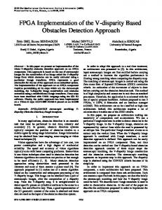
Figure 2. Pixel distribution of
3. Results. The morphological operations involved in the implementation of the described pattern spectrum algorithm, can be performed using Boolean logic in connection with delay lines at pixel level, using an adequate memory organization for the input image and the structuring element [12]. The system used in this work consists of a development platform based on the Xilinx FPGA Spartan 3E. The system includes a high speed USB2 port, 16 Mb of RAM and ROM memory, input and output ports, and support for embedded processors based on the Xilinx MicroBlaze system. The card connected to a personal computer conform a powerful design station. The operations are performed on a 128X128 input binary image, organized in a linear form as shown in Fig. 2. In each step it is required to evaluate the neighborhood of each pixel according to the specific operation. This decision can be performed by checking if the pixel under test can be induced by a translational displacement of pixels from the original image, while only displacements defined by the structuring element are considered. In other words: the structuring element is seen as a set of translation vectors, given by its pixel coordinates. A pixel in the result image can be obtained by a translational displacement of an original image pixel by the vector forming the structuring element. Accordingly, the erosion and dilation operations are carried out on a set of pixel pairs obtained by vector addition in the neighborhood of some pixel in the input image, and the vector positions in the structuring element, through Boolean operations.
(F,C) (0,1) (0,2) (0,0) (1,0) (1,1) (1,2) (2,0) (2,1) (2,2) Figure 3. Block ctrl_SubMat and Structuring Element index values. Dilation can be performed using an OR concatenation of the corresponding pixels, while an AND concatenation is used to implement the erosion operation. The FPGA‐based system is accessed through a Matlab graphical user interface. Fig. 4 shows the images obtained after an opening filter in the stage corresponding to a 5X5 structuring element. The first result was obtained from Matlab simulation, and the second image shows the result obtained from the FPGA. The block ctrl_SubMat generates the index to form a sub‐ matrix with a size corresponding to the kernel, and it is filled with the values of the original image in the local neighborhood of the processed pixel. In this block, K is the size of the structuring element in each stage, sig_k is the index counter, C‐F are the sub‐matrix index, sub_matF indicates the index C,F corresponding to the last kernel element in the structuring element, the signal enable reset the counters and enables the current block, and the signal Indx_listo indicates an index output signal. Fig. 5 shows the simulation for a 3X3 structuring element stage, and the signals obtained in the processing of the first two pixels in the submatrix.
Fig. 4 Results from an opening filter stage with a 5X5 structuring element. Binary input image; image obtained with Matlab; image obtained with the FPGA
Fig. 5 Simulation of the signals involved in the processing of the first two pixels using a 3X3 S.E. The FPGA implementation of the morphological pattern spectrum described in this paper has been designed to be used as a feature extractor for two real time image recognition applications: The first one is a biometric shape‐based hand recognition system. The system receives an image of the right hand of a subject in an unconstrained pose, which is captured with a commercial flatbed scanner. The pattern spectrum is used as a feature extractor to provide a quantitative representation of the biometric signal [10]. The second application is the use of the pecstrum for analysis of leukocytes images in support of the
cytology of bone marrow images. The pattern spectrum provides a tool to quantitatively analyze the morphological evolution of blood white cells according to their maturity stage [9]. Identification, classification and count of these forms are relevant tasks for the diagnosis and follow up of several pathologies, such as leukemia, anemia, and some other myelodysplastic syndromes. In both cases a high speed feature extraction for real time operation is required. This goal has been successfully achieved through the implementation of the algorithm on the FPGA NexysII, Xilinx, Spartan 3E. 4. Conclusion Preliminary results of a high‐speed implementation of the morphological pattern spectrum algorithm in a low‐cost system FPGA NexysII, Xilinx, Spartan 3E for image recognition applications, have been presented. The described system was designed to be used as a feature extractor for real time pattern recognition applications, such as hand‐ shape biometry, and analysis of leukocytes images in support of the cytology of bone marrow images. The system is currently under test in such applications. 5. References 1. A. Pitas and A. N. Venetsanopoulus, Non‐linear Digital Filters; Principles and Applications, Kluwer Academic Publisher, (1990). 2. P. Maragos, “Pattern spectrum and multi‐scale shape representation,” IEEE Transactions on Pattern Analysis and Machine Intelligence 11, 701‐716 (1989). 3. A. Ledda and W. Phillips, “Majority Ordering and the Morphological Pattern Spectrum”, Conf. Proc. Advanced Concepts for Intelligent Vision Systems, Antwerp, Belgium, 356‐ 363, (2005). 4. L. Yun‐Peng, L. Fang‐Cheng, and L. Cheng‐Rong, “Pattern recognition of partial discharge based on its pattern spectrum”, Proc. International Symposium on Electrical Insulating Materials, Tokio, Japan, (2005). 5. A. Valderrabano, D. Baez, and J. M. Ramirez, “Pattern Recognition in Automotive Plates¨, Proc. Midwest Symposium on Circuits and Systems, Notre Dame, Indiana, (1998). 6. A. Asano, “Texture analysis using morphology pattern spectrum and optimization of structuring element”, Proc. Int. Conf. on Image Analysis and Processing, Venice, Italy, 209‐215, (1999). 7. Ledda, P. Samyn, J. Quintelier, P. D. Baets, and W. Phillips, ”Polymer Analysis with Mathematical Morphology”, Proc. IEEE Benelux Signal Processing Symposium, Hilvarenbeek, The Netherlands, 87‐92, (2004).
8. N. Theera‐Umphon and S. Dhompongsa, “Morphological Granulometric Features of Nucleus in Automatic Bone Marrow White Blood Cell Classification”, IEEE Transactions on Information Technology in Biomedicine 11(3), 353‐359 (2007). 9. P. Gomez‐Gil, J.M. Ramírez‐Cortés, J. González‐Bernal, M. A. García‐Pedrero, C. Prieto‐ Castro, D.Valencia, R. Lobato, J.E. Alonso, "A feature extraction method based on morphological operators for automatic classification of leukocytes", 7th Mexican International Conference on Artificial Intelligence, MICAI‐2008, Conference Proceedings pp. 227‐232, Mexico, oct. 27‐31, 2008. 10. Juan Manuel Ramirez‐Cortes, Pilar Gomez‐Gil, G. Sanchez‐Perez, C. Prieto‐ Castro,“Shape‐based hand recognition approach using the morphological pattern spectrum”,Journal of Electronic Imaging, ISSN 1017‐9709, Vol. 18, No. 1, Paper No. 013012, Jan‐March,2009. 11. J. Velten, A. Kummert, “FPGA based implementation of variable sized structuring elements for 2‐D binary morphological operations”, Proc. First IEEE International Workshop on Electronics Design, Testing, and Applications, Christchurch, New Zealand, 309‐312, (2002). 12. H. Hedberg, F. Kristensen, V. Owall, “Low‐complexity binary morphology architectures with flat rectangular structuring elements”, IEEE Transactions on Circuits and Systems‐ I, Regular Papers, 55(8), 2216‐2225, (2008).